Table of Contents
Advertisement
Quick Links
1 | Overview
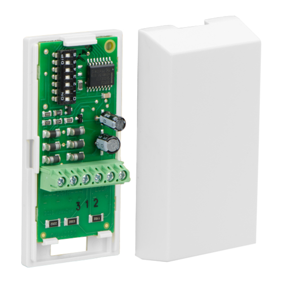
The D9127 Series POPIT Modules includes
the D9127T (with magnetic tamper switch)
and the D9127U (without tamper). They
are used with a compatible control panel
to expand beyond its standard number of
on-board initiating points. Future system
expansion is very economical as D9127
Series POPITs can be added anywhere
along the two-wire data expansion loop.
Both modules include proven technology
that combines point supervision with
individual device addressing on one pair
of wires. Screw terminals provide reliable
connections for the data expansion loop
and supervised sensor loop wiring.
The units are small and easily installed in
standard outlet boxes, above false ceilings,
closets, or other accessible locations.
2 | Installation
Use the steps in this section to install and
configure the POPIT module.
2.1 | Remove the cover
1.
Insert a small flat-head screwdriver into
one of the small slots in the side of the
POPIT.
2.
Twist the screwdriver and remove the
cover.
2.2 | Remove the PCB
1.
Grasp the terminal block on the PCB in
one hand.
2.
Three tabs hold the PCB. At the end with
the two tabs, carefully but firmly, push
one tab away from the PCB and lift the
corner.
3.
Carefully but firmly, push the other tab
away from the PCB and lift the entire
PCB from the base.
2.3 | Mount the POPIT base
Pull the wiring through the wiring opening
(refer to Figure 1). Mount the POPIT base
using the supplied hardware to prevent
shorting the PCB.
2.4 | Replace the PCB
1.
Grasp the terminal block on the PCB with
one hand. Insert the DIP switch end of the
PCB under the single tab.
2.
Carefully but firmly, pull the two tabs on
the opposite ends away from the PCB.
3.
Gently lay the PCB in place and, if
necessary, carefully, push the two tabs
toward the PCB until the PCB is firmly in
place.
2.5 | Configuration of DIP switch
Refer to Table 1 for DIP switch 0 settings and
Section 4 for DIP switch configuration settings
for ZONEX and ZONEX 2.
Control
DIP switch 0 setting
panel
D7212B1
Leave switch 0 ON.
D8112
D9112B1
D9412
Refer to 9000 Series
Operation
and Installation Guide
(P/N: 74-07692-000).
D9412G
Refer to Section 4.
D7412G
D7212G
Refer to Section 4.
D7212GV2
Refer to Section 4.
D7212GV3
Refer to Section 4.
D7212GV4
Refer to Section 4.
D9412GV4
D7412GV4
B9512G
Refer to Section 4.
B9512G-E
B8512G
B8512G-E
For additional D9127 installation
information, refer to the compatible panel
installation documentation.
Table 1: DIP switch 0 setting
3 | Wiring Instructions
For more information on POPIT installation (including wire type, length, and run) and
programming, refer to the D8125 POPEX Operation and Installation Guide (P/N: 74-04247-000)
and control panel operation, installation, and programming manuals
resistor at the farthest point on the loop for proper supervision. Replace the POPIT cover
when the wiring is completed.
NOTICE!
When using 12 AWG (0.1 mm) maximum wire, use solid wire. If you use stranded
wire, take care to insert all of the strands into the terminal block.
4
5
1
-
-
+
+
GND
-
OUT
IN
AUX
3
11
Figure 1: POPIT Wiring
Callout ― Description
1 ― D8125 POPEX Module
2 ― D9127U/T POPIT Module
3 ― Tab
4 ― DIP Switch
5 ― Reed switch (D9127T only)
6 ― Detector loop
7 ― 33 kΩ EOL resistor
8 ― Terminals (all): 12 AWG solid (maximum); 22 AWG (0.1 mm) stranded (minimum)
9 ― Zone expansion loop to other POPITs
10 ― Supervised
11 ― Wire opening of POPIT base
.
Install a 33 kΩ end-of-line
3
2
8
DATA
LOOP
-
+
+
- +
3
6
7
(-)
9
(+)
10
Advertisement
Table of Contents

Subscribe to Our Youtube Channel
Related Manuals for Bosch D9127U


Summary of Contents for Bosch D9127U
- Page 1 Insert the DIP switch end of the programming, refer to the D8125 POPEX Operation and Installation Guide (P/N: 74-04247-000) and the D9127U (without tamper). They PCB under the single tab. and control panel operation, installation, and programming manuals Install a 33 kΩ...
- Page 2 Bosch Security Systems, Inc. product www.boschsecurity.us manufacturing dates Use the serial number located on the product label and refer to the Bosch Security Systems, Inc. website at http://www.boschsecurity.com/datecodes/. ZONEX 1: Points 9 to 127 (D9412G); Points 9 to 75 (D7412G).
Need help?
Do you have a question about the D9127U and is the answer not in the manual?
Questions and answers