Advertisement
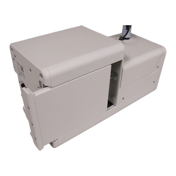
EVOS
Onstage Incubator O
™
Catalog Number AMEP4947
Doc. Part No. 710399(01)
Note: For safety and biohazard guidelines, see the "Safety" appendix in the EVOS
™
or the EVOS
M5000 Imaging System User Guide (Pub. No. MAN0017563). Read the Safety Data Sheets (SDSs) and follow the handling
instructions. Wear appropriate protective eyewear, clothing, and gloves.
Kit contents
• O
sensor
2
• O‑ring
Replace the O
sensor
2
™
1. Power off the EVOS
Onstage Incubator, then unplug the power cord, the USB cable, and the 6-pin sensor data cable from the control unit of
the incubator.
2. Turn off the regulators on the gas tanks, then detach the gas lines from the control unit.
3. Use the 2‑mm Allen key to remove the 3 button head screws, then slide out the side panel.
4. Unplug the O
sensor's connector (
2
For Research Use Only. Not for use in diagnostic procedures.
2 November 2021
2
Pub. No. MAN0025857 Rev. A.0
: plugged,
: unplugged).
1
2
1
Sensor Replacement Kit
™
M7000 Imaging System User Guide (Pub. No. MAN0018326)
• 2‑mm Allen wrench
• Instructions
USER GUIDE
2
Advertisement
Table of Contents

Subscribe to Our Youtube Channel
Related Manuals for Thermo Scientific EVOS AMEP4947


Summary of Contents for Thermo Scientific EVOS AMEP4947
- Page 1 USER GUIDE EVOS Onstage Incubator O Sensor Replacement Kit ™ Catalog Number AMEP4947 Doc. Part No. 710399(01) Pub. No. MAN0025857 Rev. A.0 ™ Note: For safety and biohazard guidelines, see the "Safety" appendix in the EVOS M7000 Imaging System User Guide (Pub. No. MAN0018326) ™...
- Page 2 5. Unscrew the O sensor. Note: You might need to use pliers (not included in the kit) to overcome the initial friction. If using pliers, do not apply excessive pressure to prevent damage to the sensor. 6. Verify that the O‑ring is installed on the new O sensor.
- Page 3 8. Plug in the O sensor's connector 9. Install the side panel and secure it with the 3 button head screws. 10. Calibrate the new O sensor. Calibrate the O sensor (EVOS M7000 Imaging System) ™ 1. Plug the power cord into the power input jack on the control unit and the wall outlet. 2.
- Page 4 6. Open the Oxygen sensor4Calibrate controls from inside the Incubator window. Calibrate controls Purge gas selection Oxygen % Begin Calibration button 7. Set the Oxygen % to the oxygen content of the air used by the system. Note: The default value for Oxygen % is 20.95% for normal compressed air. 8.
- Page 5 Calibrate the O sensor (EVOS M5000 Imaging System) ™ 1. Plug the power cord into the power input jack on the control unit and the wall outlet. 2. Connect the control unit and the computer with the USB cable, then plug the 6-pin sensor data cable from the environmental chamber into the appropriate input jack on the control unit.
- Page 6 9. Click Begin Calibration to start the calibration routine. The calibration process takes approximately three minutes to complete. When complete, the system displays the “Calibration was successful." message under the Begin Calibration button. If there was an error during calibration, the system displays the "Calibration error, please check if gas is connected." message. 10.
Need help?
Do you have a question about the EVOS AMEP4947 and is the answer not in the manual?
Questions and answers