Panasonic KX-HCM110A Service Manual
Hide thumbs
Also See for KX-HCM110A:
- Operating instructions manual (176 pages) ,
- Troubleshooting manual (24 pages) ,
- Instruction manual (4 pages)
Table of Contents
Advertisement
Quick Links
2005 Panasonic Communications Co., Ltd. All rights reserved.
Unauthorized copying and distribution is a violation of law.
IMPORTANT INFORMATION ABOUT LEAD FREE, (PbF), SOLDERING
If lead free solder was used in the manufacture of this product the printed circuit boards will be marked
PbF.
Standard leaded, (Pb), solder can be used as usual on boards without the PbF mark.
When this mark does appear please read and follow the special instructions described in this manual
ORDER NO. KMS0504060CE
1
F5
Network Camera
KX-HCM110A
(for U.S.A.)
Advertisement
Table of Contents

Related Manuals for Panasonic KX-HCM110A


Summary of Contents for Panasonic KX-HCM110A
- Page 1 ORDER NO. KMS0504060CE Network Camera KX-HCM110A (for U.S.A.) 2005 Panasonic Communications Co., Ltd. All rights reserved. Unauthorized copying and distribution is a violation of law. IMPORTANT INFORMATION ABOUT LEAD FREE, (PbF), SOLDERING If lead free solder was used in the manufacture of this product the printed circuit boards will be marked PbF. Standard leaded, (Pb), solder can be used as usual on boards without the PbF mark. When this mark does appear please read and follow the special instructions described in this manual ...
-
Page 2: About Lead Free Solder (Pbf: Pb Free)
on the use of PbF and how it might be permissible to use Pb solder during service and repair work. 1. ABOUT LEAD FREE SOLDER (PbF: Pb free) Note: In the information below, Pb, the symbol for lead in the periodic table of elements, will refer to standard solder or solder that contains lead. We will use PbF solder when discussing the lead free solder used in our manufacturing process which is made from Tin, (Sn), Silver, (Ag), and Copper, (Cu). This model, and others like it, manufactured using lead free solder will have PbF stamped on the PCB. For service and repair work we suggest using the same type of solder although, with some precautions, standard Pb solder can also be used. Caution - PbF solder has a melting point that is 50° ~ 70° F, (30° ~ 40°C) higher than Pb solder. Please use a soldering iron with temperature control and adjust it to 700° ± 20° F, (370° ± 10°C). In case of using high temperature soldering iron, please be careful not to heat too long. - PbF solder will tend to splash if it is heated much higher than its melting point, approximately 1100°F, (600°C). - If you must use Pb solder on a PCB manufactured using PbF solder, remove as much of the original PbF solder as possible and be sure that any remaining is melted prior to applying the Pb solder. - When applying PbF solder to double layered boards, please check the component side for excess which may flow onto the opposite side (See figure, below). 1.1. SUGGESTED PbF SOLDER There are several types of PbF solder available commercially. While this product is manufactured using Tin, Silver, and Copper, (Sn+Ag+Cu), you can also use Tin and Copper, (Sn+Cu), or Tin, Zinc, and Bismuth, (Sn+Zn+Bi). Please check the manufacturer’s specific instructions for the melting points of their products and any precautions for using their product with other materials. The following lead free (PbF) solder wire gauge are recommended for service of this product: 0.3mm, 0.6mm and 1.0mm. -
Page 3: How To Recognize That Pb Free Solder Is Used
1.2. HOW TO RECOGNIZE THAT Pb FREE SOLDER IS USED MAIN BOARD I/O BOARD... -
Page 4: Camera Board
CAMERA BOARD... -
Page 5: For Service Technicians
2. FOR SERVICE TECHNICIANS ICs and LSIs are vulnerable to static electricity. When replacing, the following precautions will help to prevent recurring malfunctions. 1. Cover the plastic parts with aluminum foil. 2. Ground the soldering irons. 3. Use a conductive mat on the work-table. 4. Do not grasp IC or LSI pins with bare fingers. 3. CAUTION 3.1. SAFETY PRECAUTIONS 1. Before servicing, unplug the power cord to prevent an electrical shock. 2. When replacing parts, use only manufacturer’s recommended components for safety. 3. Check the condition of power cord. Replace if wear or damage is evident. 4. After servicing, be sure to restore the lead dress, insulation barriers, insulation papers, shields, etc. 5. Before returning the serviced equipment to the customer, make the following insulation resistance test to prevent a shock hazard. 3.2. BATTERY CAUTION Danger of explosion if the battery is replaced incorrectly. Replace only with the same or equivalent type recommended by the manufacturer. Discard used batteries according to following caution: Disposal or transportation of lithium batteries should be performed by permitted, in accordance with federal, state and local guidelines. A battery continues to have no transportation limitations as long as it is separated to prevent short circuits and packed in strong packaging. Commercial firms that dispose of any quantity of lithium cells should have a mechanism in place to account for their ultimate disposition. This is a good practice for all types of commercial or industrial waste. When the lithium battery is exchanged, the clock settings are cleared. In this case, make clock settings again. Recommend Type Number: CR2032/1VC1 (BAT401) Manufactured by MATSUSHITA... -
Page 6: Insulation Resistance Test
3.3. TRADEMARKS - Adobe, Acrobat and Reader are either registered trademarks or trademarks of Adobe Systems Incorporated in the United States and/or other countries. - Microsoft, Windows, Hotmail and ActiveX are either registered trademarks or trademarks of Microsoft Corporation in the United States and/or other countries. - Pentium is a trademark or registered trademark of Intel Corporation or its subsidiaries in the United States and other countries. - Screen shots reprinted with permission from Microsoft Corporation. - All other trademarks identified herein are the property of their respective owners. - This software is based in part on the work of the Independent JPEG Group. 3.4. INSULATION RESISTANCE TEST 1. Unplug the AC power cord and short the two prongs of the plug with a jumper wire. 2. Measure the resistance value with ohmmeter between the jumpered AC plug and each exposed metal cabinet part, such as screw threads, etc. Note: Some exposed parts may be isolated from the chassis by design. These will read infinity. 3. If the measurement is outside the specified limits, there is a possibility of shock hazard. The equipment should be repaired and rechecked before it is returned to the customer. - Page 7 3.5. POWER CAUTION The power socket wall outlet should be located near this equipment and be easily accessible. 3.6. CLEANING After the camera is turned off by disconnecting the AC plug, clean the camera. 3.6.1. Cleaning the Main Unit If the lens cover has the sand or the dust, image quality may decrease. After taking away the sand or the dust on it, wipe it with a dry cloth.
-
Page 8: Specifications
Note: - Do not use alcohol, polishing powder, cleanser, benzine, thinner, wax, petroleum products or hot water to wipe the camera. Also avoid pesticide, glass cleaner or hair spray. They may cause change in the shape or color. - Do not directly touch the lens cover. Your fingerprints can cause the image to be out of focus. 4. SPECIFICATIONS Network Camera Items Specifications Zoom 10x digital zoom Pan/Tilt Angle Pan: -60° to +60°, Tilt: -45° to +20° Number of Pixels 1/4-inch CMOS Sensor 320,000 pixels Illuminance 5-10,000 lx (1-10,000 lx in color night view mode) White Balance Auto/Manual/Hold Focus Fixed 0.5m (20 inches) - Infinity Caliber Ratio (F No.) F2.8 Horizontal Viewing Angle 43° Exposure Auto Other Specifications... - Page 9 Items Specifications Video Compression JPEG (3 Levels) Video Resolution 640 x 480, 320 x 240 (default), 160 x 120 Buffered Image *1 About 125 frames (320 x 240) with time display Audio Communication 2-way Half Duplex Audio Bandwidth 300 Hz-3.4 KHz Audio Play Method Play with ActiveX Input Encoding Method Encoding with ActiveX Audio Input Built-in Microphone or External Microphone Input Terminal Audio Output *2 Audio Line Output Terminal for External Speaker Frame rate *3 Max.12 frames/second (640 x 480) Max.30 frames/second (320 x 240 or 160 x 120) Supported Protocols IPv4/IPv6 Dual-Stack IPv4: TCP, UDP, IP, HTTP, FTP, SMTP, DHCP, DNS, ARP, ICMP, POP3, NTP, IPsec, UPnP IPv6: TCP, UDP, IP, HTTP, FTP, SMTP, DNS, ICMPv6, POP3, NDP, NTP, IPsec IPsec Feature ESP Encryption, ESP Authentication Transport mode/T nnel mode IKE (Internet Key Exchange) IKE (Internet Key Pre-Shared Key Exchange) Cipher Algorithm DES-CBC, 3DES-CBC, AES-CBC Message-Digest HMAC-MD5, HMAC-SHA-1 Algorithm Message Transfer ...
-
Page 10: Main Features
*1) The maximum number of frames changes depending on the image quality and what object you buffer. *2) Connect it to an amplifier or an external speaker with a built-in amplifier. *3) Frame rate may slow down depending on the network environment, the PC performance, the image quality, enabling IPsec or what object you view. 5. MAIN FEATURES IPv6 Network Camera Your Panasonic Network Camera supports IPv6 (Internet Protocol Version 6), IPv6 was created to address the additional IP addresses that will be needed as the Internet continues to expand.Since the camera also supports IPv4 that's currently used, it is "dual stack" design will seamlessly operate while IPv6 is phased in. For more information in IPv6 you wish to visit http://www.ipv6.org/. Audio 2-way Communication (Walkie-talkie Type) Your Panasonic Network Camera now provides 2-way audio, between the camera and your PC. You will be able to hear the person on camera and respond using a microphone connected to your PC's sound card (customer-provided.) They will hear your response through the amplified speaker (customer- provided) connected to the camera. For example, the camera can be used in the following various locations: - In the baby's room, to hear if the baby is crying. - At the front door, to see and hear who is at the door. - In the children's play room, to see and hear if they are safe. Note: PLEASE NOTE that nder certain circumstances, audio/video recording may be PROHIBITED by law. This device should be used only in compliance with all applicable federal, state and local statutes. Digital zoom feature Camera has a 10x digital zoom feature. This feature allows you to increase or decrease the size of the object on the Single Camera screen, the Multi Camera screen, and the Buffered Image screen. Therefore, it will be easy to view the object that located to a distant place. A mouse wheel operation and clicking the right mouse button increase or decrease the size of the object on the Single Camera screen. Better Image Quality The CMOS sensor and the color night view mode provides better image quality and low light performance. - The CMOS sensor gives you clear image. - You can monitor live video (Motion JPEG) that refreshes its image 30 frames per second. -
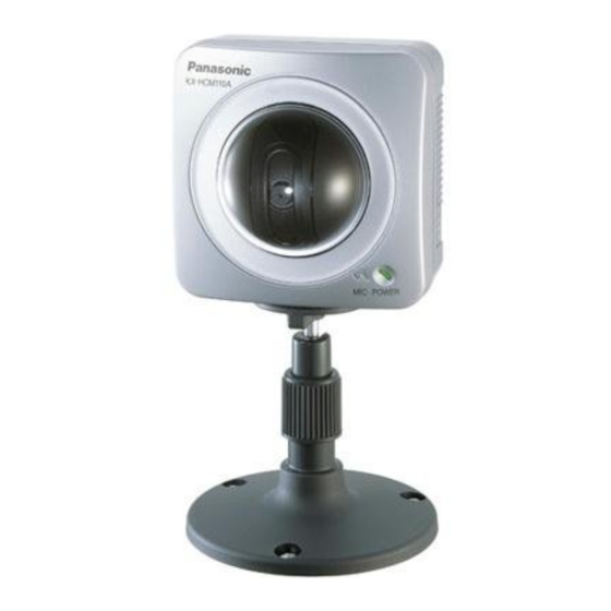
Page 11: Parts Locations
- Color night view mode allows you to monitor the camera in low illuminance. Various Camera Control Features The camera pans or tilts fast in maximum 80° per second. You can control the camera at high speed from your PC or cell phone. Alarm position feature also allows the camera to automatically turn the lens to the alarm position. Additionally, the following control features are available to easily and quickly monitor the camera. Click to Center...When yo click a certain point on the camera image, the point is centered on the image. Preset Position...You can register 8 preset positions.When yo click each button, the image switches to its position. Output Control...You can control the external devices (Open or Short to GND)(E.g., turning the light on or ringing a buzzer). Multi-Camera Support Multi-Camera page displays up to 4 cameras while supporting each audio 2-way communication. The previous model displays only 4 cameras, but this camera can switch 3 sets of 4 cameras. Additionally, the camera can displays maximum 12 cameras on a page in a static image. Multi-Language Display Top page,Single Camera and Multi-Camera page can be displayed in English, French, German, Italian, Spanish, Russian, Simplified Chinese or Japanese. The Setup, Maintenance and Support pages are displayed only in English or Japanese. Motion Detection feature Camera has a Motion Detection feature that detects movement, such as people, based on the preset threshold and sensitivity of Camera. You can buffer the camera images, transfer to an FTP server or send E-mails using the Motion Detection function as a trigger. *1 To connect in IPv6, subscribe to the ISP's "IPv4/IPv6 Dual-Stack" or "IPv6 over IPv4 Tunneling" service. The camera does not work in IPv6-only network. *2 Audio feature does not work on mobile phones. Talk button and Listen button cannot be used sim ltaneously. In IPv6, the audio feature does not work. It will be supported by the firmware update in the future. In consequence of traffic and network environments, the audio may be delayed or may break up. *3 This feature is not available when viewing on a cell phone. *4 As the magnification increases, the image quality decreases. 6. PARTS LOCATIONS 6.1. FRONT VIEW... -
Page 12: Side View
Indicator Display Power on Not on the LAN Orange Orange blinking On the LAN Orange blinking Green blinking Green Normal Operation *1 Green Automatic Setting Green blinking Setup Finished seting Green blinking Green Using Getting IP address *2 Green blinking DHCP Got IP address Green Updating Firmware Orange blinking Pressing FACTORY DEFAULT Orange blinking Turning off RESET button (The camera restarts after that.) Orange blinking (About a 2-second UPnP Failure interval) Internal Failure Red blinking *1) The indicator turns orange if the camera is not connected to the LAN. *2) The indicator blinks orange if the camera is not connected to the LAN. 6.2. SIDE VIEW... -
Page 13: Bottom View
6.3. BOTTOM VIEW 6.4. REAR VIEW... - Page 14 Note: To listen to audio from the camera, an external amplified speaker (customer-provided) must be connected to the camera. The connector used is a stereo type, similar to that used by amplified PC speakers. Though the connector is stereo, the audio is not. 7. CONNECTING YOUR NETWORK CAMERA 7.1. PREPARATION Prepare the following before connecting the Network Camera. - Set up software (Setup CD-ROM) - PC to fulfill the system requirements. - Ethernet Router for LAN Connection. - Ethernet cable (two pieces of Category 5 straight cable). System Requirements for your PC Your PC (Personal Computer) and network must meet the following technical specifications for the camera to work properly. For IPv4 Connection...
- Page 15 10/100 Mbps network card installed Web Browser Internet Explorer 6.0 or later (Not included on the Setup CD-ROM) Audio Audio input/output feature (Microphone or speaker) For IPv6 Connection Item Description Operation System Microsoft Windows XP Service Pack 1 or later For viewing single camera Pentium III (800 MHz or greater is recommended.) For viewing multiple cameras Pentium 4 (1.8 GHz or greater is recommended.) Protocol TCP/IP protocol (HTTP, TCP, UDP, IP, DNS, ICMPPv6, NDP) Interface 10/100 Mbps network card installed Web Browser Internet Explorer 6.0 or later (Not included on the Setup CD-ROM) Audio Audio input/output feature (Microphone or speaker) Note: See Panasonic Network Camera support website at http://panasonic.co.jp/pcc/products/en/netwkcam/ for the latest information about web browser. 7.2. CONNECT THE CAMERA TO YOUR ROUTER Connect the camera to your router with an Ethernet cable to set up the camera. - Before you begin the installation, the UPnP feature in your router needs to be enabled. Usually, the default setting disables this feature. For more info, please visit, http://panasonic.co.jp/pcc/products/en/ netwkcam/ or contact your router's manufacturer. - These instructions assume your PC is already connected to the Internet and your home network includes a router that is UPnP and Play) compliant.
-
Page 16: Turn The Camera On
- The camera will be connected to your router using a "straight" Cat5 network cable (customer-provided). 1. Connect the Ethernet cable (customer-provided) to the camera. Note: These instructions assume your PC is already connected to the Internet and your network includes a router. 2. Connect the Ethernet cable to your router. 7.3. TURN THE CAMERA ON Inserting the AC plug of the AC cord to the outlet powers up the camera. 1. Connect the power cord of the AC adaptor to the DC In jack, and plug the AC cord into the outlet. - The AC cord is used as the main disconnect device, ensure that the socket-outlet is located/installed near the equipment and is easily accessible. - Use only specified Panasonic AC adaptor PQLV202 (Order No. PQLV202Y). -
Page 17: Set Up The Camera
- If the indicator does not light green, see page 3 of the Troubleshooting on the Setup CD-ROM. - A noise can be heard during pan/tilt operation. This is normal. 2. Hook the AC adaptor cord to the Hook for AC adaptor cord. 7.4. SET UP THE CAMERA Important - To avoid any possible problems, temporarily disable any firewall or antivirus software. - This procedure explains installation of the camera on the same network that your PC is part of. - Before proceeding, close your web browser. 1. Insert the Setup CD-ROM into the CD-ROM drive of the PC. (If the Network Camera Setup window is not displayed automatically, double-click "Setup.exe" file on the Setup CD-ROM.) - Page 18 2. Click [Camera Setup]. - If Windows Security Alert is displayed, click [Unblock]. 3. Select the camera to set up and click [Execute]. - This program searches for the cameras that are connected to the router and displays the MAC Addresses, IP addresses and Port Numbers. - The MAC Address on the rear side of the camera shows which camera you select on the Camera List window.
- Page 19 Note: - If the indicator does not light green, check the connection. - If more than 20 minutes have passed since the camera was turned on, the camera cannot be set up from the Setup Program. In this situation, disconnect the AC cord from the outlet, and reconnect it again. - The Setup Program may not list any cameras due to your firewall or antivirus software settings on your PC. If you cannot disable your firewall or antivirus software, you can set up the camera entering the camera MAC address on the following window. The camera's MAC address can be found on the label affixed to the back of each camera. 4. Click [Automatic Setup (Local Access Only)]. - For the first time installation or after pressing the FACTORY DEFAULT RESET button, only [Automatic Setup (Local Access Only)] can be selected. To set up the camera with Static or DHCP settings, after performing the [Automatic Setup (Local Access Only)], run the Setup Program again and select [Manual Setup].
- Page 20 5. Enter the user name and password you wish to use, and click [Save]. 6. The Enter Network Password window is displayed. Enter the user name and password that were set, and click [OK]. 7. When the Single Camera page is displayed,the setup is completed. - If Security Warning window is displayed to install ActiveX Controls, click [Yes]. - To install ActiveX Controls on Microsoft Windows XP Service Pack 2, see "Security Warning window on Microsoft Windows XP Service Pack 2".
-
Page 21: Listening To Camera Audio - Talking To The Camera
Note: To insure that the most current image is displayed,I nternet Explorer should be configured as follows.This will not have any negative result on normal use. 1. While viewing any website, Click [Tools] [Internet Options]. 2. In the section "Temporary Internet Files", click [Settings] and check [Every visit to the page]. 7. Click [Next] to set up the Internet access to the camera. 7.5. LISTENING TO CAMERA AUDIO - TALKING TO THE CAMERA 1. Access the camera. - The Top page is displayed. 2. Click the [Single] tab at the top of the page. 3. The audio control bar is displayed at the top of the screen. Listening or Talking is selected using the 2 icons. For general sers, the feature m st be enabled, otherwise it will not be displayed. Audio Feature... - Page 22 Note: - Talk button and Listen button cannot be used simultaneously. Talk feature is stopped during listening. Talk feature can be used only for a user. Listen feature can be sed for maximum 10 users. If the audio is interrupted, reduce the max.bandwidth. In this case, the number of users for listening are reduced. - Audio features such as camera microphone sensitivity and mute during pan/tilt can be set up on the Audio page. - If you are running other applications or opening multiple windows, the audio may be interrupted or delayed. - When the image is refreshed during any operation such as preset registration or a web browser refresh, the volume is reset to the defa lt (midrange) position. Audio that was muted is enabled. - The audio may be interrupted due to your PC's performance or network environment. Reduce the max.bandwidth. - If the camera is accessed while the PC user visits other websites, the active microphone may pick up audio from the PC's speakers. Be ...
- Page 23 - Talk feature cannot be used from a PC when the camera is accessed via a proxy server. - If you cannot listen to the audio or talk from your PC, see 2.5 Audio Problems in the Troubleshooting section of the Installation/ Troubleshooting on the Setup CD-ROM. - If you use external microphone, excessive length or poor quality microphone cable can cause a degradation in audio quality. - The cables for the external microphone must be less than 7 m (about 23 feet) long. - To talk to the camera from your PC, an external amplified speaker such as the Panasonic RP-SPT70 or equivalent (customer-provided) must be connected to the camera. The speaker connects to the camera with a stereo audio cable similar to that used by your PC. Though the connector is stereo, the audio is not. - The external microphone input terminal does not correspond to a line level. Audio may be distorted when the line level is input. Audio distortion will be solved if you insert the following circuits. Under no circumstance should high level audio, such as from a speaker, be connected to this input terminal. Doing so is likely to damage the camera. 8. DISASSEMBLY INSTRUCTIONS 8.1. HOW TO REMOVE MAIN BOARD AND I/O BOARD...
- Page 24 1. Remove four Screws (B). 2. Remove Cabinet Cover. 3. Remove three Screws (A). 4. Remove Main Board and I/O Board from Cabinet Body. 5. Remove Connector A, Connector B and Connector ...
- Page 25 6. Remove FFC Cable from Main Board and I/O Board. 8.2. HOW TO REMOVE EYE BLOCK...
- Page 26 1. Remove four Screws (B). 2. Remove Cabinet Cover. 3. Remove three Screws (A). 4. Remove Main Board and I/O Board from Cabinet Body. 5. Remove Connector A, Connector B and Connector ...
- Page 27 6. Remove two Screws (A). 7. Remove Pan Motor Unit, Pan Gear and Eye Block from Cabinet Body. 9. THE CAUTIONS AT THE TIME OF ASSEMBLY 9.1. CAUTIONS FOR SHEET ATTACHMENT Attach the Main PCB Sheet to the Main Board and then attach the Plastic Parts to it.
- Page 28 Caution: See the Figures for the position in the attachment of the Main PCB Sheet and the Sheet. Press the Flat Surface shown in the Figure, then press the whole sheet securely to avoid peeling. The Sheet should not cover the connector in FIG. 2. 9.2. CAUTIONS FOR FFC CABLE ATTACHMENT Process the FFC Cable to insert to the connectors of the I/O Board and the Main Board.
- Page 29 9.3. CAUTIONS FOR MIC ATTACHMENT Insert the MIC Rubber, the MIC and the LED Lens into the Upper Cabinet and fix them with the Screws (A).
- Page 30 9.4. CAUTIONS FOR MAIN BOARD ATTACHMENT Attach the component that connects the Main Board and the I/O Board with the FFC Cable, to the Upper Cabinet and fix it with the Screw (A).
- Page 33 9.5. CAUTIONS FOR PLASTIC PATS ATTACHMENT...
-
Page 34: Trouble Shouting
10. TROUBLE SHOUTING 10.1. BASIC OPERATION... - Page 35 10.2. CHECK FOR OTHER FUNCTION...
- Page 36 10.3. CHECK FOR SCREEN BLOCK ...
- Page 37 10.4. CHECK FOR SOUND BLOCK...
- Page 38 10.4.1. Built-in Microphone...
- Page 39 10.4.2. External Microphone 10.4.3. Speaker Output...
- Page 40 10.4.4. Common Flow Of Built-in Microphone, External Microphone And Speaker Output 10.4.5. Check For LAN Block...
- Page 41 10.5. CHECK FOR MOTOR DRIVING BLOCK 10.5.1. Check For The Action Of Pan...
- Page 42 10.5.2. Check For The Action Of Tilt...
- Page 43 10.6. CHECK FOR POWER SUPPLY BLOCK...
- Page 45 10.7. CHECK FOR RTC CIRCUIT 10.8. CHECK FOR I/O TERMINAL...
- Page 46 10.9. CHECK FOR LED CIRCUIT...
- Page 47 10.10. CHECK FOR INITIALIZATION...
-
Page 48: Factory Default Reset Button
10.11. CHECK FOR VERSION UPGRADE 11. THE WAY OF THE INITIALIZE 11.1. FACTORY DEFAULT RESET BUTTON... -
Page 49: Resetting The Camera To Factory Default
The camera has a Factory Default Reset button on the rear. Pressing the Factory Default Reset button resets the camera to factory default. If you lose your user name and password, use this button to reset the camera. - Press the Factory Default Reset button for 1 second when the camera is - The indicator blinks orange, and turn off for 10 seconds. - Do not turn off the camera until the indicator lights green. Note: - Internal clock will not be reset, but the time format will return to AM/PM mode. Set it again. - All buffered images are deleted when resetting the camera to factory default. - The reset operation takes about 1 minute. 11.2. RESETTING THE CAMERA TO FACTORY DEFAULT This feature will be executed and all camera settings reset to factory default directly after the Execute button is clicked. 1. Click [Reset to Factory Default] on the Maintenance page. 2. Click [Execute]. - The indicator blinks orange, and turn off for 10 seconds. - All camera settings (user name, password, IP address, subnet mask etc.) are reset to factory default. - If the camera is reset to factory default, the network connection modechanges to [Automatic Setup]. Reconfigure the camera seeing the Getting Started. Note: - Internal clock will not be reset, but the time format will return to AM/PM mode. Set it again. - Please refer to Operating Instructions for default values. - Pressing FACTORY DEFAULT RESET button resets the camera to the factory default. - All buffered images are deleted when resetting the camera to factory ... -
Page 50: Cpu Peripheral Block
- The reset operation takes about 1 minute. - Do not turn off the camera during the reset operation. 12. NETWORK CAMERA KX-HCM110A BLOCK DIAGRAM 13. CIRCUIT DESCRIPTION 13.1. CPU PERIPHERAL BLOCK - The IC103 is a system LSI for a network camera containing the CPU - The power supply voltages are +3.3V (I/O) and +1.8V. - The CPU is a 32-bit RISC CPU and performs mainly hardware control, TCP/IP protocol processing and applications such as http and FTP. - The clock setting is 65.536MHz, which is the four times of 16.384MHz oscillation in the X101 by PLL. - There are two types of external bus: the General-purpose bus through SRAM I/F and the bus for SDRAM only. - The General bus is connected to a Flash Memory for program storage. - The capacity of the Flash Memory (IC101) is 32Mbit (2Mx16bit); the program, the setting information for the network camera and the MAC address are stored. - The SDRAM (IC105) is 64Mbit (4Mx16bit) and used for the CPU processing work, the communication data storage and the sound and image data storage. - The RESET IC (IC104) monitors the power supply voltage, detects the rising edge of +3.3V and generates the Hardware Reset Signal. - The IC405 is a RTC (Real Time Clock) and is used for the time setting of the image transfer. It is backed up at power-off by a lithium battery (BAT401). The I/F with the CPU has a dedicated controller. (5-line I/F) - The Encryption block inside the IC103 is an Ipsec communication encryption engine and is used at the software protocol processing. Signal Flow 1. When a request from the PC is received through LAN, the CGI command is analyzed at the CPU and the requested image/sound data are generated. 2. The JPEG image and sound data accumulated on the SDRAM are formed in IP packet by the protocol processing. -
Page 51: Camera Block
3. If the Ipsec is not encrypted, it is sent without change. If it is encrypted, this is carried out in the Encryption Block and a header is added to send to the Ethernet MAC part. 13.2. CAMERA BLOCK <Basic Circuit Operation> With a 0.35umCMOS process, this CMOS image sensor is composed of one chip that integrates the sensor assembly with the image processing DSP. Individual pixels composed of four transistors have micro-lenses to increase sensitivity, and light energy is converted to analog voltage. After that, the analog pixel voltage is converted to digital in a 10-bit AD Converter (ADC), at which time Correlated Double Sampling (CDS) dramatically reduces Fixed Pattern Noise (FPN). The digitized analog pixel voltage data is gamma and color corrected, goes through color space conversion, and with PCLK, Hsync, and Vsync employed as timing interface signals, YUV is sequentially output digitally in 8-bit wide format. Image processing functions such as Auto-Iris (AE) and Auto White Balance (AWB) are built in and controlled automatically according to an internal algorithm in the chip. Auto-Iris (AE) is controlled by the shutter speed. - Page 52 Registry settings are performed in I2C<SCK, SDA> (IC2:22/23 pin) by the CPU (IC103) on the CPU board. CMOS Color Image Sensor (IC2) CMOS Color Image Sensor (IC2) Operating voltage: +2.8V - E+2.8VA: Analog block voltage - E+2.8VD: Digital block voltage Package:40pin CLCC Image sensor and image-processing circuit embedded Total pixels: 652 ~492 pixels Effective pixels: 652~488 pixels Image area: 1/4inch optical format Color filter: RGB Bayer format Input clock: 25MHz (To be supplied through the oscillation circuit in IC1 and X1.) 13.3. JPEG BLOCK - The IC103 is a system LSI for a network camera containing the CPU. - The JPEC Encode Circuit, the Memory Management Unit(MMU) and the SDRAM Controller are built into this LSI. - The image data(YUV) inputted from a Camera Block is captured to the SDRAM through the JPEG Encode Block, the MMC and the SDRAM Controller. (1) - The captured YUV data are inputted to the JPEG Encode Block again ...
- Page 53 and the JPEG processing is performed here. The compressed encode data are stored to the SDRAM. (2) - A header is added to the encoded JPEG data by a direction of the CPU and it is transferred to a network after a protocol processing. (3) 13.4. SOUND BLOCK External Microphone Jack (CN603) Used with the external microphone. Speaker Jack (CN604) Used when connecting a speaker with a built-in amplifier, when the sound is output from a camera. Microphone Detection (Q603) When the external microphone plug is not inserted, pins 3 and 2 of the Microphone Jack (CN603) are short-circuited and a base current is supplied to Q603 through R603, R632 and R629 so that the Q603 goes ON and a collector (MIC_S signal) goes LOW. Alternatively, when the microphone plug is inserted, pins 3 and 2 of the CN603 become open so that the Q603 goes OFF and the MIC_S signal goes HIGH. From this signal, the CPU detects the microphone status. The CPU turns the microphone SW on and off in the PCM Codec (IC601) for the external or the built-in microphone, as appropriate. ALC Amplifier (IC602: For the built-in microphone, IC603: For the external microphone) Power Supply: 3.3V...
- Page 54 Amplifier for Auto Level Control PCM Codec (IC601) Power Supply Voltage: 3.3V Clock Frequency: Contains a built-in PLL function and generates a clock from the BCLK (256 KHz). Contains an amplifier, LPF, gain adjustment, AD/DA converter, host I/F, PCM serial I/F and speaker output function. Flow of Sound Signal [Microphone sound] 1. The sound data input from pin 1 of the built-in microphone connector (CN607) is amplified by the amplifier in the PCM Codec (IC601) and the ALC (IC603), then input as the built-in microphone to the PCM Codec (IC601) again. When the level of the input sound signal is more than the specified value, the gain is changed and the output signal level is kept constant at the ALC (IC603). Sound distortion is controlled when the input is excessive. 2. When the external microphone is attached to the microphone jack (CN603), the sound signal input from pin 2 of the CN603 is amplified by the amplifier in the PCM Codec (IC601) and the ALC (IC602), then input as the external (microphone) to the PCM Codec (IC601) again The ALC (IC602) works in the same way as the IC603. 3. In the PCM Codec (IC601), after the sound signal is switched between the built-in microphone and the external microphone by a register setting from the host, amplification, AD conversion and gain adjustment are performed. The sampling frequency of the A/D conversion is 8kHz and it is converted to the PCM in the format of 8bit and law. Then, 64kbps data are output to the ASIC (101) through the Serial I/F. The data transfer of the Serial I/F is BCLK (256 kHz). 4. The data compression of 32kbps is performed in the ADPCM Block of the ASIC (101) and the data transferred as sound data.
-
Page 55: Lan Block
[Speaker Sound] 1. The ADPCM sound data are sent from the PC and, after data decompression in the ADPCM block of the ASIC (101), the data are transferred as the sound data of 64kbps to the PCM Codec (IC601) through the Serial I/F. 2. After the law to linear conversion, amplification and DA conversion, they are output to pin 2 of the speaker jack (CN604) as sound output signal in the PCM Codec (IC601). 13.5. LAN BLOCK Composed of the IC103 (CPU), the IC202 (ETHER-PHY), the T601 (Transformer) and the CN605 (RJ45). The T605 (Transformer) obtains isolation between the Set and the Ethernet. The IC103 (CPU) and the IC202 (ETHER-PHY) are connected by a signal called MIIBus and it makes Ether net data sending and receiving possible. Sending The electrical signal sent from the IC103 is converted to Ethernet data at the IC202 and sent from the CN605 through the T601. Receiving The Ethernet data received from the CN605 is converted to electrical data at the IC202 and received to the IC103. -
Page 56: Power Supply Block
13.6. MOTOR DRIVING BLOCK The pan tilt is performed, as the ASIC (IC101) mounted on the Main Board controls the Motor Driver (IC201). The home position of the pan tilt operation is detected by the Pan Photo Sensor (IC303 on the Main Board) and the Tilt Photo Sensor (IC71 on the Sensor FPC). 13.7. POWER SUPPLY BLOCK... - Page 57 13.8. OTHERS 13.8.1. I/O Terminal - The Input terminal has two systems; both of them are connected to the Input Port of the IC103 GPIO. - Due to Internal Pull-up Resistance, the PNP Transistor (Q504, Q503) on the following level is usually in the OFF state and the Input Port connected to the collector is at L level. - If the terminal is short-circuited with the GND or the signal of L level is input, the PNP Transistor goes ON and the Input Port goes to H level.
-
Page 58: Terminal Guide Of Ics, Transistors And Diodes
- The CPU checks the state of this port regularly to detect a change in this signal. - The Output terminal is controlled by the Output Port of the IC103. When the Port output is L, the transistor (Q501) on the following level is OFF and, when the output is H, the transistor is ON. This transistor has open collector output and it controls external equipment via external pull-up. 13.8.2. Clear Setting SW - The Clear Setting SW (SW101) is connected to the Input Port of the GPIO. It is usually at H level and goes to L level, when the SW is pressed. - The CPU monitors this Input Port regularly and, if it detects that this SW is pressed longer than a specified period, the setting values other than the RTC are returned to factory settings. 13.8.3. LED - The LED (LED601) has two-color LEDs (red and green). When the transistor (Q601, Q602) connected to each LED is turned ON/OFF via the Output Port of the IC103, it controls the ON/OFF of the LED. 14. TERMINAL GUIDE OF ICS, TRANSISTORS AND DIODES... -
Page 59: How To Replace A Flat Package Ic
15. HOW TO REPLACE A FLAT PACKAGE IC 15.1. PREPARATION - PbF (: Pb free) Solder - Soldering Iron Tip Temperature of 700°F ± 20°F (370°C ± 10°C) Note: We recommend a 30 to 40 Watt soldering iron. An expert may be able to use a 60 to 80 Watt iron where someone with less experience could overheat and damage the PCB foil. - Flux Recommended Flux: Specific Gravity 0.82. Type RMA (lower residue, non-cleaning type) Note: See ABOUT LEAD FREE SOLDER (PbF: Pb free) (). 15.2. PROCEDURE 1. Tack the flat pack IC to the PCB by temporarily soldering two diagonally opposite pins in the correct positions on the PCB. -
Page 60: Removing Solder From Between Pins
Be certain each pin is located over the correct pad on the PCB. 2. Apply flux to all of the pins on the IC. 3. Being careful to not unsolder the tack points, slide the soldering iron along the tips of the pins while feeding enough solder to the tip so that it flows under the pins as they are heated. 15.3. REMOVING SOLDER FROM BETWEEN PINS 1. Add a small amount of solder to the bridged pins. 2. With a hot iron, use a sweeping motion along the flat part of the pin to draw the solder from between the adjacent pads. -
Page 61: Cabinet And Electrical Parts Location
16. CABINET AND ELECTRICAL PARTS LOCATION 17. ACCESSORIES AND PACKING MATERIALS... -
Page 62: Replacement Parts List
18. REPLACEMENT PARTS LIST Note:... -
Page 63: Cabinet And Electrical Parts
1. RTL (Retention Time Limited) The marking (RTL) indicates that the Retention Time is limited for this item. After the discontinuation of this assembly in production, the item will continue to be available for a specific period of time. The retention period of availability depends on the type of assembly and the laws governing parts and product retention. At the end of this period, the assembly will no longer be available. 2. Important safety notice Components identified by the mark indicates special characteristics important for safety. When replacing any of these components, only use specified manufacture's parts. 3. The S mark means the part is one of some identical parts. For that reason, it may be different from the installed part. 4. ISO code (Example: ABS-94HB) of the remarks column shows quality of the material and a flame resisting grade about plastics. 5. RESISTORS & CAPACITORS Unless otherwise specified; All resistors are in ohms ( ), k=1000 , M=1000k All capacitors are in MICRO FARADS ( F), p= ( F) *Type & Wattage of Resistor 18.1. CABINET AND ELECTRICAL PARTS... -
Page 64: Main Board Parts
Ref. No. Part No. Part Name & Description Remarks PSYF1057Y1 CABINET COVER ABS+PC-V0 PSJE1043Z LEAD WIRE,FFC CABLE PSWEHCM110N MECHANISM ASS Y,EYE BLOCK ABS-V0 PSKM1116T1 CABINET BODY ABS+PC-V0 PSWQHCM110N PAN MOTOR UNIT PSMG1007Z RUBBER PARTS,MIC PSJM1006Z MICROPHONE PSHR1322Y OPTIC CONDUCTIVE PARTS,LED LENS PSHR1318Z PAN GEAR POM-HB PSNPD050080 SPACER PSNPD050080 SPACER PSKV1041Z COVER,DOME PC-HB PSMH1278Z CHASSIS PSMH1277Z CHASSIS PSQA2830Z LABEL,CAUTION PSGT2663Z NAME PLATE ... - Page 65 Ref. No. Part No. Part Name & Description Remarks PCB1 PSWP1HCM110A MAIN BOARD ASS’Y (RTL) (ICS) IC103 C1DB00001114 IC IC104 C0EBE0000231 IC IC105 C3ABPG000134 IC IC201 C0GBF0000020 IC IC202 C1CB00001689 IC IC303 RPI-352 IC S IC305 C0BBBA000044 IC IC403 C0DBAFZ00054 IC IC404 C0DBAFZ00054 IC IC405 C1CB00001918 IC IC407 C0CBCAD00039 ...
- Page 66 C132 ECUV1C104ZFV 0.1...
- Page 67 Ref. No. Part No. Part Name & Description Remarks C133 ECUV1C104ZFV 0.1 C134 ECUV1C104ZFV 0.1 C135 ECUV1C104ZFV 0.1 C136 ECUV1C104ZFV 0.1 C137 ECUV1E103KBV 0.01 C138 ECUV1E103KBV 0.01 C139 ECUV1C104ZFV 0.1 C140 ECUV1C104ZFV 0.1 C141 ECUV1E103KBV 0.01 C142 ECUV1E103KBV 0.01 C143 ECUV1C104ZFV 0.1 C144 ECUV1C104ZFV 0.1 C145 ...
- Page 68 C401 F2B1E1020001 1000...
- Page 69 Ref. No. Part No. Part Name & Description Remarks C402 PFCX1EY106ZF 10 S C403 PFCX1EY106ZF 10 S C404 ECUV1E104ZFV 0.1 C405 ECUV1E104ZFV 0.1 C406 PFCX1EY106ZF 10 S C407 PFCX1EY106ZF 10 S C408 ECUV1C104ZFV 0.1 C411 ECUV1E103KBV 0.01 C412 ECUV1E103KBV 0.01 C413 F4Z0J4760001 C414 F4Z0J4760001 C415 ECUV1C104ZFV ...
- Page 70 R111 ERJ3GEYJ103 10k ...
- Page 71 Ref. No. Part No. Part Name & Description Remarks R114 ERJ3GEYJ103 10k R116 ERJ3GEYJ103 10k R117 ERJ3GEYJ103 10k R118 ERJ3GEYJ103 10k R120 ERJ3GEYJ101 R121 ERJ3GEYJ105 1M R122 ERJ3GEYJ103 10k R123 ERJ3GEYJ103 10k R124 ERJ3GEYJ101 R125 ERJ3GEY0R00 R126 ERJ3GEYJ271 R130 ERJ3GEYJ330 R133 ERJ3GEYJ473 47k R134 ERJ3GEYJ473 47k ...
- Page 72 R326 ERJ3GEYJ104 100k ...
- Page 73 Ref. No. Part No. Part Name & Description Remarks R328 ERJ3GEYJ104 100k R329 ERJ3GEYJ103 10k R330 ERJ3GEYJ103 10k R331 ERJ3GEYJ101 R401 ERJ3GEYJ152 1.5k R402 ERJ3GEYJ100 R403 ERJ3GEYJ100 R404 ERJ3GEYJ470 R405 ERJ3GEYJ470 R406 ERJ3GEY0R00 R407 ERJ3GEY0R00 R408 ERJ3GEYJ332 3.3k R409 ERJ3EKF2702 R410 ERJ3EKF1202 R411 ERJ3EKF4702 47k R412 ...
-
Page 74: I/O Board Parts
(COMPONENTS PARTS) Ref. No. Part No. Part Name & Description Remarks RA201 D1H84704A037 RESISTOR ARRAY RA202 D1H84704A037 RESISTOR ARRAY RA502 PSLQR2C601MT RESISTOR ARRAY RA503 PSLQR2C601MT RESISTOR ARRAY (SWITCH) SW101 EVQPSM02K SWITCH (CRYSTAL OSCILLATORS) X101 H0J163500014 CRYSTAL OSCILLATOR X201 H0J250500038 CRYSTAL OSCILLATOR (OHTERS) E1 PSHX1245Z PLASTIC PARTS,SHEET E2 PSHX1205Z PLASTIC PARTS,SHEET E3 PSHR1325Z SPACER 18.4. I/O BOARD PARTS Ref. No. Part No. - Page 75 Ref. No. Part No. Part Name & Description Remarks C620 F1J0J1060006 C621 ECUV1E104ZFV 0.1 C622 ECUV1C104ZFV 0.1 C623 F1J0J1060006 C624 F1J0J1060006 C625 ECUV1C104ZFV 0.1 C626 ECUV1C104ZFV 0.1 C627 ECUV1H122KBV 0.0012 C628 ECUV1H122KBV 0.0012 C629 ECUV0J105KBV 1 S C630 ECUV1E104ZFV 0.1 C631 F1J0J1060006 C632 ECUV1A224KBV 0.22 S C633 ...
-
Page 76: For The Schematic Diagram
R602 ERJ3GEYJ750 Ref. No. Part No. Part Name & Description Remarks R603 ERJ3GEYJ222 2.2k R604 ERJ3GEYJ222 2.2k R606 ERJ3GEYJ102 1k R607 ERJ3GEYJ102 1k R608 PQ4R18XJ100 S R609 ERJ3GEY0R00 R610 ERJ3GEYJ103 10k R611 ERJ3GEYJ103 10k R612 ERJ3GEYJ473 47k R613 ERJ3GEYJ203 20k R614 ERJ3GEYJ154 150k R615 ERJ3GEYJ750 R616 ... -
Page 77: Schematic Diagram
Note: 1. DC voltage measurements are taken with an oscilloscope or a tester with a ground. 2. The schematic diagrams and circuit board may be modified at any time with the development of new technology. 20. SCHEMATIC DIAGRAM 20.1. WAVEFORM 21. CIRCUIT BOARD 21.1. MAIN BOARD (COMPONENT VIEW) 21.2. MAIN BOARD (BOTTOM VIEW) 21.3. I/O BOARD (COMPONENT VIEW) 21.4. I/O BOARD (BOTTOM VIEW) 21.5. CAMERA BOARD (COMPONENT VIEW) 21.6. CAMERA BOARD (BOTTOM VIEW) A HCM110A... - Page 78 +2.8V +2.8VD +2.8VA +3.3V PSUP1577Z KX-HCM110A CAMERA BOARD...
- Page 79 R13 C26 KX-HCM110A CAMERA BOARD...
- Page 80 PSUP1464Z TP_DCIN TP_RX+ TP_TX+ SA611 SA616 TP_+3.3V TP_EXMICIN C642 TP_MICS C639 R619 SA612 R629 R618 TP_RX- IC601 TP_LEDG TP_IOGND1 R630 R634 TP_TX- C647 C618 C601 C613 SA615 C623 C646 KX-HCM110A I/O BOARD...
- Page 81 DA602 L612 CN605 C608 C610 L611 L608 Q601 R615 CN606 LED601 R606 C640 CN607 R602 R637 C617 R603 R636 R617 T601 SA604 SA605 C626 R635 R633 SA607 C624 KX-HCM110A I/O BOARD...
- Page 82 C116 C124 C111 R121R120 C110 R211 C121 R119 L101 C113 R212 X101 R213 L402 R214 C203 R126 C118 Q402 IC104 L404 C418 R507 R309 C519 D404 C120 C432 C416 C443 C414 R506 C513 CN202 CN501 R231 R232 KX-HCM110A MAIN BOARD...
- Page 83 R135 R229 R403 C332 C224 R341 C420 C412 R411 IC404 C524 C327 C213 R230 C405 C401 R217 C112 C438 C442 R218 C215 C501 C439 C441 R420 C428 IC409 C431 L406 C429 R419 C427 C433 R417 C434 TP_3.3VM KX-HCM110A MAIN BOARD...
- Page 86 10Base Hub Connection (un-communicating)
- Page 87 10Base Hub Connection (un-communicating) 10Base Hub Connection (Communicating)
- Page 88 TO:TILT MOTOR IC71 FROM:MAIN BOARD TO:CMOS SENS0R KX-HCM110A FPC...
- Page 89 15 15 28 AGND28 29 STROBE 16 16 30 RESETB 0.1u 31 ENB 17 17 32 AVDD32 33 AGND33 18 18 34 DGNDC34 35 VDDC35 19 19 0.1u 20 20 100p FLT2 21 21 22 22 0.1u DGND KX-HCM110A CAMERA BOARD...
- Page 90 TP_12V TP_DCIN CN602 D601 L602 6.8u L601 TP_LEDG TP_LEDR CN601 R644 Q602 L605 R608 10 1/8W Q601 L603 R643 L604 S1 S2 R642 +A3.3V R606 (10) (11) (12) (13) (14) C606 (15) TP_BIMICIN 6.3V47u 0.047u CN607 C613 R611 (16) TP_MICGND 0.047u (17) C612...
- Page 91 TP_LED3.3V TP_+3.3V +3.3V CN606 L608 (10) (11) (12) (13) (14) (15) (16) +A3.3V R625 1 Vcc Output (17) IO_IN2 O_IN1 2 DET Input IO_OUT IC602 R641 C646 LED_3.3V LED_R TP_BIMICAMP1 LED_G C618 R621 R614 150k 3.3k 0.47u TP_BIMICAMP2 C615 330p (18) (19) (20)
- Page 92 +3.3V +3.3VCAM DGND R516 PHO_STOP DGND R520 DEVREST R521 PDOWN R522 R523 L502 CAMCLK R525 VSYNC R526 HSYNC RA502 YUV[0] YUV[1] YUV[2] YUV[3] DGND YUV[7-0] RA503 DGND YUV[4] YUV[5] YUV[6] TILT_SEN YUV[7] R501 CN502 DGND DGND KX-HCM110A MAIN BOARD No.5...
- Page 93 1.5K DATA CE 9 Fout R401 D401 DGND DGND Q401 L401 +12V_IN R406 IC403 R402 TP_GND2 Vout DGND DGND DGND Q402 L402 R407 IC404 R403 Vout DGND RF_PDN L405 Q403 R419 IC409 R417 Vout KX-HCM110A MAIN BOARD No.4 (1/2) DGND...
- Page 94 TP_MOTOR +5VM L403 +3.3VCAM TP_3.3VCAM L407 TP_D3.3V +3.3V DGND L404 TP_1.8V +1.8V IC407 Vout DGND TP_3.3VM +3.3VM KX-HCM110A MAIN BOARD No.4 (2/2)
- Page 95 EXMNWE0 R317 (14) RA303 DEVREST EXD[8] MND[8] EXD[9] MND[9] (15) SD_WAIT EXD[10] MND[10] EXD[11] MND[11] R343 RA304 EXD[12] MND[12] EXD[13] MND[13] EXD[14] MND[14] DGND EXD[15] MND[15] (16) R313 (17) EXMCS2 (18) SD_MCLK R315 (19) nSD_INT KX-HCM110A MAIN BOARD No.3 (1/2)
- Page 96 43 MNA5 MND0 MND[1] 44 MNA4 MND1 MND[2] 45 MNA3 MND2 DGND MND[3] (10) 46 MNA2 MND3 DGND MND[4] (11) 47 MNA1 MND4 MND[5] (12) 48 nMNRE MND5 (13) (14) (15) R344 (16) (17) (18) (19) KX-HCM110A MAIN BOARD No.3 (2/2)
- Page 97 (13) +3.3V IC201 (14) P-GND24 P_MOT1 OUT1 P_MOT2 OUT2 P_MOT3 OUT3 P_MOT4 OUT4 S-GND P-GND18 (15) T_MOT1 OUT5 T_MOT2 OUT6 T_MOT3 (16) OUT7 T_MOT4 OUT8 (17) VS12 P-GND13 C205 (18) W4 W3 W2 W1 DGND KX-HCM110A MAIN BOARD No.2 (1/2)
- Page 98 0.1u DGND R218 DGND 51.1(1%) +3.3VM CN202 C222 0.1u C223 NC(2125) R231 R232 R233 R234 (10) DGND (11) CCD_TILT[0] (12) CCD_TILT[1] (13) CCD_TILT[2] (14) CCD_TILT[3] CN201 R206 (15) R207 (16) R208 (17) R209 (18) DGND KX-HCM110A MAIN BOARD No.2 (2/2)
- Page 99 DGND +3.3V (10) (11) (12) (13) RF_LINK PHY_Select RF_PDN RF_TXD RF_RXD RF_nRST FCLK DCLK R122 SOUT DGND SCLK DATA MIC_S LED_G LED_R T1 T2 T3 RELAY nSENSOR1 nSENSOR2 DEVREST PDOWN PAN_S (14) TILT_S (15) PHO_STOP KX-HCM110A MAIN BOARD No.1 (1/2)
- Page 100 NC36 C161 SDA[11] SDA[9] (10) SDA[10] SDA[8] (11) SDD[0] SDA[0] SDA[7] (12) DGND SDA[1] SDA[6] (13) SDA[2] SDA[5] SDA[3] SDA[4] DGND VDD27 VSS28 0.1u C136 SDRAM RTCLK RTCD RTCE RTWR DGND RTINT (14) (15) KX-HCM110A MAIN BOARD No.1 (2/2)
- Page 101 1.8V DC JACK Filter 1.8V 4.0V MIC JACK PCM CODEC (AN6123M S) (AK2 308LV-E1) 32M F lash SP JACK 25M Hz 64M S-DRAM (AN6123M S) RJ-45 LA N Trance LAN PHY Clear Setting SW 2pin Reset IC KX-HCM110A BLOCK DIAGRAM...
Need help?
Do you have a question about the KX-HCM110A and is the answer not in the manual?
Questions and answers