Table of Contents
Advertisement
Quick Links
Emergency Locator Transmitter
Description, Operation, Installation and Maintenance Manual
This manual includes data for the equipment that follows:
Component
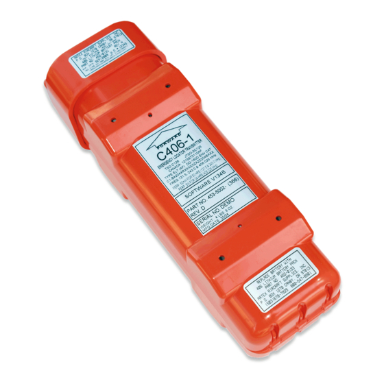
Emergency Locator Transmitter
Emergency Locator Transmitter
C406-1 Series
Part No.
Model No.
453-5002
C406-1
453-5003
C406-1HM
25-62-10
ARTEX PRODUCTS / ACR ELECTRONICS, INC.
5757 Ravenswood Rd, Ft. Lauderdale, FL 33312
Page 1 of 67
Feb 28/2019
570-5001 Rev. J
Initial Issue JUN 30/1999
Cage Code: 18560
Advertisement
Table of Contents
Troubleshooting


Need help?
Do you have a question about the C406-1 Series and is the answer not in the manual?
Questions and answers