Table of Contents
Advertisement
Emergency Locator Transmitter
Description, Operation, Installation and Maintenance Manual
This manual includes data for the equipment that follows:
Component
Emergency Locator Transmitter
B406-4
Part No.
453-5004
25-62-03
ARTEX PRODUCTS / ACR ELECTRONICS, INC.
Model No.
B406-4
Initial Issue DEC 02/1999
5757 Ravenswood Rd, Ft. Lauderdale, FL 33312
Page 1 of 70
Feb 28/2019
570-5004 Rev. N
Cage Code: 18560
Advertisement
Table of Contents
Troubleshooting

Related Manuals for ARTEX B406-4


Summary of Contents for ARTEX B406-4
- Page 1 Component Part No. Model No. Emergency Locator Transmitter 453-5004 B406-4 Page 1 of 70 25-62-03 Feb 28/2019 570-5004 Rev. N Initial Issue DEC 02/1999 ARTEX PRODUCTS / ACR ELECTRONICS, INC. 5757 Ravenswood Rd, Ft. Lauderdale, FL 33312 Cage Code: 18560...
- Page 2 ARTEX PRODUCTS / ACR ELECTRONICS, INC DESCRIPTION, OPERATION, INSTALLATION AND MAINTENANCE MANUAL B406-4 (453-5004) PROPRIETARY INFORMATION This document contains proprietary information and such information may not be disclosed to others for any purpose, nor used for manufacturing purposes without written permission from ACR Electronics.
-
Page 3: Record Of Revisions
ARTEX PRODUCTS / ACR ELECTRONICS, INC DESCRIPTION, OPERATION, INSTALLATION AND MAINTENANCE MANUAL B406-4 (453-5004) RECORD OF REVISIONS REVISION CHANGE DATE REVISION CHANGE DATE RELEASE Dec 02/1999 ECO 1418 Jun 22/2000 DCN 1641 Apr 11/2001 DCN 1747 Jul 19/2001 DCN 1965... -
Page 4: Service Bulletin List
ARTEX PRODUCTS / ACR ELECTRONICS, INC DESCRIPTION, OPERATION, INSTALLATION AND MAINTENANCE MANUAL B406-4 (453-5004) SERVICE BULLETIN LIST SERVICE ISSUE MANUAL MANUAL SUBJECT BULLETIN NO DATE REV NO REV DATE 25-62-03 Page 4 of 70... -
Page 5: List Of Effective Pages
ARTEX PRODUCTS / ACR ELECTRONICS, INC DESCRIPTION, OPERATION, INSTALLATION AND MAINTENANCE MANUAL B406-4 (453-5004) LIST OF EFFECTIVE PAGES SUBJECT PAGE DATE SUBJECT PAGE DATE Title Page Feb 28/19 Test and Fault Isolation (cont) Oct 14/13 Notices Oct 14/13 Oct 14/13... -
Page 6: Table Of Contents
ARTEX PRODUCTS / ACR ELECTRONICS, INC DESCRIPTION, OPERATION, INSTALLATION AND MAINTENANCE MANUAL B406-4 (453-5004) TABLE OF CONTENTS RECORD OF REVISIONS ..........................3 SERVICE BULLETIN LIST ........................... 4 LIST OF EFFECTIVE PAGES........................5 TABLE OF CONTENTS ..........................6 LIST OF FIGURES ............................. 9 INTRODUCTION ............................. - Page 7 ARTEX PRODUCTS / ACR ELECTRONICS, INC DESCRIPTION, OPERATION, INSTALLATION AND MAINTENANCE MANUAL B406-4 (453-5004) Inspection and Test Procedures ....................27 Checklist ..........................27 Preparation .......................... 28 Coax Cables and Wiring Connections Inspection – Item 1 ............28 Mounting Tray and Hardware Inspection – Item 2 ..............28 Battery Pack Inspection –...
- Page 8 ARTEX PRODUCTS / ACR ELECTRONICS, INC DESCRIPTION, OPERATION, INSTALLATION AND MAINTENANCE MANUAL B406-4 (453-5004) Buzzer ............................51 Location ..........................51 Installation .......................... 51 Wiring ............................52 General Considerations and Recommendations ..............52 Remote Switch Panel Harness Fabrication and Installation ............52 Buzzer Wiring Fabrication .....................
-
Page 9: List Of Figures
DESCRIPTION, OPERATION, INSTALLATION AND MAINTENANCE MANUAL B406-4 (453-5004) LIST OF FIGURES Figure 1 B406-4 ELT and Mounting Frame Assembly ................18 Figure 2 Remote Switch Panel Assembly Front View ................18 Figure 3 Buzzer ..........................19 Figure 4 Battery Pack Assembly ......................19 Figure 5 Antennas .......................... -
Page 10: Introduction
Installation e) Registration Illustrated Parts List 2) In the United States, the B406-4 ELT must be installed and maintained in accordance with the requirements herein and 14 CFR, FAR Parts 43, and 91; and other airworthiness requirements, as applicable. -
Page 11: Model Description
SUBTASK 25-62-03-990-001 A. B406-4 1) The B406-4 is a type AF (Automatic Fixed) ELT, which transmits on 121.5, 243.0, and 406 MHz. 2) The ELT is enclosed within a multi-piece mounting frame consisting of a mounting tray assembly, protective top cover assembly and mounting frame cap assembly. - Page 12 ARTEX PRODUCTS / ACR ELECTRONICS, INC DESCRIPTION, OPERATION, INSTALLATION AND MAINTENANCE MANUAL B406-4 (453-5004) CATEGORY SECTION DESCRIPTION Temperature/Altitude 4.5.4 In-Flight Loss of Cooling Temperature Variation Humidity 7.0/8.0 Operational Shock and Crash Safety/Vibration Explosion 10.0 Waterproofness 11.0 Fluids Susceptibility 12.0 Sand and Dust 13.0...
-
Page 13: Frequency Allocations
SUBTASK 25-62-03-990-002 B. Discussion 1) The 406 MHz transmitter frequency of the B406-4 ELT was originally 406.025 MHz. In order to comply with COSPAS-SARSAT frequency allocation requirements, changes to the 406 MHz frequency may occur since the original release of this product. -
Page 14: List Of Acronyms, Abbreviations, And Definitions
ARTEX PRODUCTS / ACR ELECTRONICS, INC DESCRIPTION, OPERATION, INSTALLATION AND MAINTENANCE MANUAL B406-4 (453-5004) TASK 25-62-03-990-805 5. List of Acronyms, Abbreviations, and Definitions SUBTASK 25-62-03-990-001 Term Definition Advisory Circular – A Federal Aviation Administration (USA) bulletin with special information. For the purposes of this document, the acronym AC does not refer to electrical alternating current. - Page 15 ARTEX PRODUCTS / ACR ELECTRONICS, INC DESCRIPTION, OPERATION, INSTALLATION AND MAINTENANCE MANUAL B406-4 (453-5004) G-Switch A velocity switch that detects sudden de-acceleration and is used to automatically activate an ELT. May also be referred to as a “crash sensor”. Light Emitting Diode – Semiconductor device that emits light when current is passed through it.
-
Page 16: References
Transmitters (ELT)” SUBTASK 25-62-03-990-002 B. Other Documents 1) The following documents are available on-line at the Artex products web site at www.acrartex.com, or from ACR Electronics upon request. a) 570-1000, “ELT Test Set (ETS) Operation Manual” b) 570-6501, “ELT/NAV Interface -B Description, Operation, Installation and Maintenance Manual”... -
Page 17: Description And Operation
ARTEX PRODUCTS / ACR ELECTRONICS, INC DESCRIPTION, OPERATION, INSTALLATION AND MAINTENANCE MANUAL B406-4 (453-5004) DESCRIPTION AND OPERATION TASK 25-62-03-870-801 1. Description SUBTASK 25-62-03-870-001 A. Functional Overview 1) The ELT automatically activates during a crash and transmits the standard sweep tone on 121.5 and 243.0 MHz. -
Page 18: Components
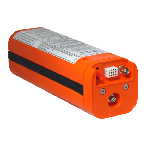
SUBTASK 25-62-03-870-002 B. Components 1) The B406-4 ELT main assembly is housed in a high impact, fire resistant, polycarbonate plastic case, which is enclosed in a protective mounting frame assembly made of similar material. See Figure 1 B406-4 ELT and Mounting Frame Assembly. -
Page 19: Figure 3 Buzzer
Figure 3 Buzzer 4) The battery pack for the B406-4 ELT consists of four “D” size lithium manganese dioxide cells connected in series. In an effort to increase the safety of the battery pack, a number of features were designed into the battery pack. -
Page 20: Figure 5 Antennas
DESCRIPTION, OPERATION, INSTALLATION AND MAINTENANCE MANUAL B406-4 (453-5004) 5) Five dual-input antennas are approved for use with the B406-4 ELT. Selection of the proper antenna is dependent upon end use, aircraft configuration, speed, and other factors. See Figure 5 Antennas. -
Page 21: Operation
1) See Figure 6 ELT Operational Flow Diagram. 2) A primary feature of the B406-4 ELT is its simplicity of operation. As long as the ELT is connected to the remote switch panel harness ELT connector, such that pins 5 and 8 are jumpered (G-switch loop), it will activate in the event of a crash. -
Page 22: Normal Operation
ARTEX PRODUCTS / ACR ELECTRONICS, INC DESCRIPTION, OPERATION, INSTALLATION AND MAINTENANCE MANUAL B406-4 (453-5004) 6) To take the ELT from an “ACTIVE” state back to an “INACTIVE” state, a “RESET” must occur. See SUBTASK 25-62-03-870-004. 7) A warning buzzer is required under C126 TSO approval. The buzzer is powered by the aircraft battery. -
Page 23: Specifications
TASK 25-62-03-870-803 3. Specifications SUBTASK 25-62-03-870-001 A. Environmental and Physical 1) Table 2 lists the environmental and physical specifications of the B406-4 ELT. NOTE: For automatic activation, the higher threshold of 4.5 ft/sec (2.3 ) is specified in accordance with Eurocae ED-62. Use of the higher threshold crash sensor has been approved by the FAA as a deviation to TSO C126 (FAA Reference #98-130S-108, February 6, 1998). -
Page 24: Electrical
ARTEX PRODUCTS / ACR ELECTRONICS, INC DESCRIPTION, OPERATION, INSTALLATION AND MAINTENANCE MANUAL B406-4 (453-5004) SUBTASK 25-62-03-870-002 B. Electrical 1) Table 3 lists the electrical specifications of the B406-4 ELT. CRITERIA PARAMETER CHARACTERISTIC ± 2 KHz (Initial) 406.025 MHz ± 5 KHz (5 years) -
Page 25: Antennas
ARTEX PRODUCTS / ACR ELECTRONICS, INC DESCRIPTION, OPERATION, INSTALLATION AND MAINTENANCE MANUAL B406-4 (453-5004) SUBTASK 25-62-03-870-003 C. Antennas 1) Table 4 lists the specifications of the antennas approved for use with the B406-4 ELT. CHARACTERISTIC PARAMETERS 110-320 110-328-01 110-333 110-337... -
Page 26: Test And Fault Isolation
ARTEX PRODUCTS / ACR ELECTRONICS, INC DESCRIPTION, OPERATION, INSTALLATION AND MAINTENANCE MANUAL B406-4 (453-5004) TEST AND FAULT ISOLATION TASK 25-62-03-750-801 1. Inspection and Test Regulatory Requirements SUBTASK 25-62-03-990-001 A. United States 1) In accordance with FAR Part 91, Subpart C, § 91.207 (d), the ELT must be inspected within 12 calendar months after the last inspection for: a) Proper installation;... -
Page 27: Inspection And Test Procedures
ARTEX PRODUCTS / ACR ELECTRONICS, INC DESCRIPTION, OPERATION, INSTALLATION AND MAINTENANCE MANUAL B406-4 (453-5004) TASK 25-62-03-750-802 2. Inspection and Test Procedures SUBTASK 25-62-03-990-001 A. Checklist 1) Table 5 provides a list of the ELT inspection and testing requirements, a copy of which may be used as a checklist to verify inspection and test completion. -
Page 28: Preparation
ARTEX PRODUCTS / ACR ELECTRONICS, INC DESCRIPTION, OPERATION, INSTALLATION AND MAINTENANCE MANUAL B406-4 (453-5004) SUBTASK 25-62-03-000-001 B. Preparation 1) Remove the ELT in accordance with SUBTASK 25-62-03-990-002. 2) Remove the battery pack in accordance with SUBTASK 25-62-03-990-002. SUBTASK 25-62-03-220-001 C. Coax Cables and Wiring Connections Inspection – Item 1 1) Check remote panel harness connector for corrosion bent or broken pins and other damage. -
Page 29: G-Switch Functional Check - Item 4A
SUBTASK 25-62-03-750-002 G. G-Switch Functional Check (Helicopter Models Only)– Item 4b 1) This procedure outlines the steps required to test the five-axis G-switch installed in ARTEX Helicopter Model (HM) ELTs. 2) Testing of the primary and five axis G-switch can be accomplished by simulating a rapid deceleration in the required direction of the G-switch. -
Page 30: Performance Testing Setup
ARTEX PRODUCTS / ACR ELECTRONICS, INC DESCRIPTION, OPERATION, INSTALLATION AND MAINTENANCE MANUAL B406-4 (453-5004) Figure 7 ELT Orthogonal Axes 3) Keep G-switch loop and 50-ohm load installed on the antenna port from Item 4a installed. 4) Utilizing the sturdy padded surface, hold the ELT 10 inches (26.1 Centimeters) above the test area and thrust down forcefully maintaining a level axis into the pad to test the -X axis (see Figure 7). -
Page 31: 121.5 Mhz Frequency Measurement - Item 5A
ARTEX PRODUCTS / ACR ELECTRONICS, INC DESCRIPTION, OPERATION, INSTALLATION AND MAINTENANCE MANUAL B406-4 (453-5004) Figure 8 Performance Testing Equipment Setup SUBTASK 25-62-03-750-004 I. 121.5 MHz Frequency Measurement – Item 5a 1) Connect the measuring device, referring to SUBTASK 25-62-03-750-003 on page 29. -
Page 32: 406 Mhz Power Output Measurement - Item 5E
ARTEX PRODUCTS / ACR ELECTRONICS, INC DESCRIPTION, OPERATION, INSTALLATION AND MAINTENANCE MANUAL B406-4 (453-5004) 3) Wait three minutes. 4) Measure the frequency. Measure the frequency after the three-minute waiting period. The frequency must be within the tolerance specified in Table 3 on page 24. -
Page 33: Digital Message Verification - Item 5G
ARTEX PRODUCTS / ACR ELECTRONICS, INC DESCRIPTION, OPERATION, INSTALLATION AND MAINTENANCE MANUAL B406-4 (453-5004) Figure 9 Current Draw Test Setup 5) Read the current draw on the ammeter. Measured current should be 0 µA (micro-amps), and must not be more than 6 µA. -
Page 34: Elt Reset Check - Item 5H
ARTEX PRODUCTS / ACR ELECTRONICS, INC DESCRIPTION, OPERATION, INSTALLATION AND MAINTENANCE MANUAL B406-4 (453-5004) b) The left hand example in Figure 10 Short and Long 406 MHz Message Examples is an ELT programmed for “User Protocol ELT with Serial Number”, with a test Hex ID. The right hand example is an ELT programmed for “Standard Location Protocol ELT with Serial Number”. -
Page 35: Antenna Test - Item 7
ARTEX PRODUCTS / ACR ELECTRONICS, INC DESCRIPTION, OPERATION, INSTALLATION AND MAINTENANCE MANUAL B406-4 (453-5004) 7) Activate the ELT by placing the cockpit remote switch in the “ON” position. The panel light will illuminate and stay on steady. NOTE: The LED on the ELT will begin flashing continuously when the ELT is activated. -
Page 36: Troubleshooting
ARTEX PRODUCTS / ACR ELECTRONICS, INC DESCRIPTION, OPERATION, INSTALLATION AND MAINTENANCE MANUAL B406-4 (453-5004) TASK 25-62-03-810-801 3. Troubleshooting SUBTASK 25-62-03-810-001 A. Self-Test Error Troubleshooting Guidelines 1) Table 6 describes the ELT self-test LED error codes (i.e., flash codes), their probable causes, and possible solutions. - Page 37 ARTEX PRODUCTS / ACR ELECTRONICS, INC DESCRIPTION, OPERATION, INSTALLATION AND MAINTENANCE MANUAL B406-4 (453-5004) CODE PROBABLE CAUSE POSSIBLE SOLUTION Battery low Low power output 3A fuse on battery pack circuit board faulty 3-Flash (cont.) Improper programming Verify 406 MHz programming...
-
Page 38: Elt Troubleshooting Guidelines
ARTEX PRODUCTS / ACR ELECTRONICS, INC DESCRIPTION, OPERATION, INSTALLATION AND MAINTENANCE MANUAL B406-4 (453-5004) SUBTASK 25-62-03-810-002 ELT Troubleshooting Guidelines Table 7 provides ELT troubleshooting guidelines for installation and operational issues. SYMPTOM PROBABLE CAUSE POSSIBLE SOLUTION Improper wiring Verify wiring Check for frayed insulation... -
Page 39: Removal
ARTEX PRODUCTS / ACR ELECTRONICS, INC DESCRIPTION, OPERATION, INSTALLATION AND MAINTENANCE MANUAL B406-4 (453-5004) REMOVAL TASK 25-62-03-010-801 1. ELT SUBTASK 25-62-03-010-001 A. ELT Removal 1) See Figure 11 ELT Removal Sequence. Figure 11 ELT Removal Sequence 2) Loosen the mounting frame cap thumbscrews. -
Page 40: Battery
ARTEX PRODUCTS / ACR ELECTRONICS, INC DESCRIPTION, OPERATION, INSTALLATION AND MAINTENANCE MANUAL B406-4 (453-5004) TASK 25-62-03-050-801 2. Battery SUBTASK 25-62-03-050-001 A. Battery Pack Removal CAUTION: THE BATTERY PACK CONTAINS ELECTROSTATIC DISCHARGE SENSITIVE (ESD) COMPONENTS AND IT MUST BE HANDLED WITH CARE. IF POSSIBLE, WEAR A GROUNDED WRIST STRAP WHEN HANDLING THE BATTERY PACK DURING INSTALLATION ACTIVITIES. -
Page 41: Material Or Equipment Return
ARTEX PRODUCTS / ACR ELECTRONICS, INC DESCRIPTION, OPERATION, INSTALLATION AND MAINTENANCE MANUAL B406-4 (453-5004) TASK 25-62-03-500-801 Material or Equipment Return SUBTASK 25-62-03-510-001 A. Shipment Information 1) If any material or equipment is to be returned to the factory, under warranty or otherwise, ACR... -
Page 42: Installation
ARTEX PRODUCTS / ACR ELECTRONICS, INC DESCRIPTION, OPERATION, INSTALLATION AND MAINTENANCE MANUAL B406-4 (453-5004) INSTALLATION TASK 25-62-03-410-801 1. Regulatory Requirements and Guidelines SUBTASK 25-62-03-990-001 A. For US Registered aircraft: WARNING: FAILURE TO REGISTER THIS ELT WITH NOAA BEFORE INSTALLATION COULD RESULT IN A MONETARY FORFEITURE BEING ISSUED TO THE OWNER. -
Page 43: Canada
ARTEX PRODUCTS / ACR ELECTRONICS, INC DESCRIPTION, OPERATION, INSTALLATION AND MAINTENANCE MANUAL B406-4 (453-5004) SUBTASK 25-62-03-990-003 D. Canada 1) All installations must be performed in accordance with Canadian Aviation Regulations (CAR) Part V, Chapter 551, Paragraph 551.104. SUBTASK 25-62-03-990-004 E. Other Countries 1) Installations in aircraft outside of the United States and Canada, must be performed in accordance with applicable regulatory authority rules and regulations. -
Page 44: Mounting Tray
THESE COMPONENTS. THESE SAME CHEMICAL AGENTS MAY ALSO CAUSE CORROSION OF ELECTRICAL CONNECTIONS. 1) Select a suitable location for the mounting tray. See Figure 13 B406-4 ELT Outline and Dimensions. Refer to these dimensions when determining mounting location. Figure 13 B406-4 ELT Outline and Dimensions 2) Locate the mounting tray such that the ELT mounting frame cap has at least 5 inches (127 mm) of clearance for installation and removal. -
Page 45: Installation
4) Mark the four holes needed for mounting the tray, using the tray as a pattern. The hole pattern is also illustrated in Figure 13 B406-4 ELT Outline and Dimensions on page 44. 5) Drill the four mounting holes with a #19 or 4.25 mm drill. -
Page 46: Antenna
SUBTASK 25-62-03-990-001 A. Selection 1) Use only antennas approved for use with the B406-4 ELT. The ELT will not work properly without being connected to an antenna for which it was designed. 2) Verify the antenna selected matches the requirements of the specific installation. Considerations include aircraft maximum rated speed, location restrictions, and any other considerations specific to the installation. -
Page 47: Figure 15 Rod Antenna 110-320 And Blade Antenna 110-328-01 Outlines And Dimensions
ARTEX PRODUCTS / ACR ELECTRONICS, INC DESCRIPTION, OPERATION, INSTALLATION AND MAINTENANCE MANUAL B406-4 (453-5004) Figure 15 Rod Antenna 110-320 and Blade Antenna 110-328-01 Outlines and Dimensions 25-62-03 Page 47 of 70... -
Page 48: Figure 16 Blade Antennas 110-333 And 110-337 Outlines And Dimensions
ARTEX PRODUCTS / ACR ELECTRONICS, INC DESCRIPTION, OPERATION, INSTALLATION AND MAINTENANCE MANUAL B406-4 (453-5004) Figure 16 Blade Antennas 110-333 and 110-337 Outlines and Dimensions 25-62-03 Page 48 of 70... -
Page 49: Figure 17 Blade Antenna 110-337-11 Outline And Dimensions
ARTEX PRODUCTS / ACR ELECTRONICS, INC DESCRIPTION, OPERATION, INSTALLATION AND MAINTENANCE MANUAL B406-4 (453-5004) Figure 17 Blade Antenna 110-337-11 Outline and Dimensions 25-62-03 Page 49 of 70... -
Page 50: Remote Switch Panel
ARTEX PRODUCTS / ACR ELECTRONICS, INC DESCRIPTION, OPERATION, INSTALLATION AND MAINTENANCE MANUAL B406-4 (453-5004) TASK 25-62-03-450-803 4. Remote Switch Panel SUBTASK 25-62-03-450-001 A. Location NOTE: In most cases, panel space and wiring have been pre-provisioned by the aircraft manufacturer for the G737 control panel (remote switch panel assembly); however, location and installation requirements are defined for installations in aircraft not pre-provisioned for this remote switch panel. -
Page 51: Buzzer
ARTEX PRODUCTS / ACR ELECTRONICS, INC DESCRIPTION, OPERATION, INSTALLATION AND MAINTENANCE MANUAL B406-4 (453-5004) TASK 25-62-03-450-804 5. Buzzer SUBTASK 25-62-03-450-001 A. Location CAUTION: PLACING THE BUZZER IN THE COCKPIT IS NOT RECOMMENDED DUE TO THE POTENTIAL FOR DISTRACTION. THE BUZZER PRODUCES A LOUD, SIREN-TYPE SOUND WHEN THE ELT IS ACTIVATED. -
Page 52: Wiring
ARTEX PRODUCTS / ACR ELECTRONICS, INC DESCRIPTION, OPERATION, INSTALLATION AND MAINTENANCE MANUAL B406-4 (453-5004) TASK 25-62-03-450-805 6. Wiring SUBTASK 25-62-03-990-001 A. General Considerations and Recommendations CAUTION: IF GROUND OR OTHER CONNECTIONS ARE BROKEN OR OTHERWISE DAMAGED, THE ELT IS STILL CAPABLE OF AUTOMATIC ACTIVATION; HOWEVER, THE COCKPIT REMOTE SWITCH MAY BE INCAPABLE OF RESETTING THE ELT AND OPERATION MAY NOT BE INDICATED ON THE REMOTE SWITCH LED. -
Page 53: Figure 20 Remote Switch Panel Harness Wiring Diagram
ARTEX PRODUCTS / ACR ELECTRONICS, INC DESCRIPTION, OPERATION, INSTALLATION AND MAINTENANCE MANUAL B406-4 (453-5004) Figure 20 Remote Switch Panel Harness Wiring Diagram 25-62-03 Page 53 of 70... - Page 54 ARTEX PRODUCTS / ACR ELECTRONICS, INC DESCRIPTION, OPERATION, INSTALLATION AND MAINTENANCE MANUAL B406-4 (453-5004) 2) Fabricate a 4-wire harness long enough to reach from the ELT to the cockpit remote switch panel, allowing enough slack to provide a drip loop at the ELT end and a service loop at the cockpit remote switch panel end.
-
Page 55: Buzzer Wiring Fabrication
ARTEX PRODUCTS / ACR ELECTRONICS, INC DESCRIPTION, OPERATION, INSTALLATION AND MAINTENANCE MANUAL B406-4 (453-5004) SUBTASK 25-62-03-450-002 C. Buzzer Wiring Fabrication 1) Fabricate the following wires, which correspond with the wires on the buzzer: NOTE: Use appropriately coded wires, such that the wires can be identified and terminated at the appropriate locations. -
Page 56: Coax Cables Installation
ARTEX PRODUCTS / ACR ELECTRONICS, INC DESCRIPTION, OPERATION, INSTALLATION AND MAINTENANCE MANUAL B406-4 (453-5004) Figure 21 Remote Switch Panel Harness Wiring at ELT End 5) Crimp male terminal pins (151-6627) to each of the wire ends, using Molex crimp tool 63811-3300, or an equivalent tool for 0.062 in. -
Page 57: Antenna Connections
ARTEX PRODUCTS / ACR ELECTRONICS, INC DESCRIPTION, OPERATION, INSTALLATION AND MAINTENANCE MANUAL B406-4 (453-5004) SUBTASK 25-62-03-450-005 F. Antenna Connections 1) Connect the two coax cables to the antenna, making sure the cables are routed and supported, such that there is no tensile load (i.e., strain) on the connections. -
Page 58: Elt Installation
ARTEX PRODUCTS / ACR ELECTRONICS, INC DESCRIPTION, OPERATION, INSTALLATION AND MAINTENANCE MANUAL B406-4 (453-5004) TASK 25-62-03-410-802 7. ELT Installation SUBTASK 25-62-03-410-001 A. Installation and Test 1) See Figure 22 ELT Installation Sequence. Figure 22 ELT Installation Sequence 2) Verify the ELT local switch is in the “OFF” position. -
Page 59: Harness Elt Receptacle Sealing
ARTEX PRODUCTS / ACR ELECTRONICS, INC DESCRIPTION, OPERATION, INSTALLATION AND MAINTENANCE MANUAL B406-4 (453-5004) NOTE: Steps (1) through (11) are applicable any time the ELT has been removed and undergoes reinstallation. Step (12) is only applicable at initial installation or if the wiring and/or coax cables have been disturbed. -
Page 60: Battery Pack Installation
ARTEX PRODUCTS / ACR ELECTRONICS, INC DESCRIPTION, OPERATION, INSTALLATION AND MAINTENANCE MANUAL B406-4 (453-5004) TASK 25-62-03-450-806 8. Battery Pack Installation SUBTASK 25-62-03-450-001 A. Battery Reinstallation CAUTION: THE BATTERY PACK CONTAINS ELECTROSTATIC DISCHARGE SENSITIVE (ESD) COMPONENTS AND IT MUST BE HANDLED WITH CARE. IF POSSIBLE, WEAR A GROUNDED WRIST STRAP WHEN HANDLING THE BATTERY PACK DURING INSTALLATION ACTIVITIES. -
Page 61: New Battery Installation
ARTEX PRODUCTS / ACR ELECTRONICS, INC DESCRIPTION, OPERATION, INSTALLATION AND MAINTENANCE MANUAL B406-4 (453-5004) 8) Fit the battery pack into place on the ELT, while dressing the wires away from the standoffs to avoid pinching the wires between the standoffs and battery pack. -
Page 62: Appendix A - Elt Registration
ARTEX PRODUCTS / ACR ELECTRONICS, INC DESCRIPTION, OPERATION, INSTALLATION AND MAINTENANCE MANUAL B406-4 (453-5004) APPENDIX A – ELT REGISTRATION TASK 25-62-03-990-801 1. Background Information SUBTASK 25-62-03-990-001 A. Hex ID Code 1) Each 406 MHz ELT is programmed with a unique hex ID code (i.e., registration code) that is transmitted to the SAR satellite system. -
Page 63: Registration
1) In the United States, the National Oceanic and Atmospheric Administration (NOAA) is the registration agency. 2) Specific registration web sites and information may be found at: a) The Artex products web site at www.acrartex.com, which has links to online registration sites and also a link to registration forms and instructions for a number of countries. -
Page 64: Illustrated Parts List
SUBTASK 25-62-03-990-001 A. Ordering Information 1) Approved parts may be ordered from ACR Electronics or any authorized dealer. CONTACT INFORMATION Sales, ACR Electronics, Inc / Artex Products 5757 Ravenswood Rd Fort Lauderdale, FL 33312-6645, USA Phone: (954) 981-3333 Fax: (954) 983-5087... -
Page 65: Explanation Of Detailed Parts List Entries
ARTEX PRODUCTS / ACR ELECTRONICS, INC DESCRIPTION, OPERATION, INSTALLATION AND MAINTENANCE MANUAL B406-4 (453-5004) TASK 25-62-03-990-803 3. Explanation of Detailed Parts List Entries SUBTASK 25-62-03-990-001 A. Fig # & Item Column 1) The first number at the top of the column is the figure number of the corresponding illustration. -
Page 66: Upa (Units Per Assembly) Column
ARTEX PRODUCTS / ACR ELECTRONICS, INC DESCRIPTION, OPERATION, INSTALLATION AND MAINTENANCE MANUAL B406-4 (453-5004) 3) Assemblies, subassemblies, and detail parts subject to modification, deletion, addition, or replacement by an issued service bulletin, are annotated to indicate both pre- and post-service bulletin configurations. -
Page 67: Detailed Parts List
ARTEX PRODUCTS / ACR ELECTRONICS, INC DESCRIPTION, OPERATION, INSTALLATION AND MAINTENANCE MANUAL B406-4 (453-5004) TASK 25-62-03-990-804 4. Detailed Parts List Figure 25 B406-4 ELT Main Assembly and Installation FIG # ITEM PART # 1234 NOMENCLATURE Protective Top Cover Assembly 452-3052... - Page 68 ARTEX PRODUCTS / ACR ELECTRONICS, INC DESCRIPTION, OPERATION, INSTALLATION AND MAINTENANCE MANUAL B406-4 (453-5004) Washer, Lock Internal Tooth SS #8 – 247-0800 Nut, 8-32 x 1/4” Hex SS – 241-0832 B406-4 Main Assembly 453-5004 – 591-0999 . Label, Hex Code –...
-
Page 69: Figure 26 Electrical Components
ARTEX PRODUCTS / ACR ELECTRONICS, INC DESCRIPTION, OPERATION, INSTALLATION AND MAINTENANCE MANUAL B406-4 (453-5004) Figure 26 Electrical Components FIG # ITEM PART # 1234 NOMENCLATURE Control Panel G737 453-0161 . Label, ELT Cautionary Use Advisory (Optional) – 591-0428 Receptacle, 12-Pin 151-5012 . -
Page 70: Figure 27 Antennas
ARTEX PRODUCTS / ACR ELECTRONICS, INC DESCRIPTION, OPERATION, INSTALLATION AND MAINTENANCE MANUAL B406-4 (453-5004) Figure 27 Antennas FIG # PART # 1234 NOMENCLATURE Antenna, 406 Blade (319 Dual Input) 110-337 Antenna, 406 Blade (Dual Input) 110-328-01 Antenna, Tri-Band Blade, White (Dual Input)
Need help?
Do you have a question about the B406-4 and is the answer not in the manual?
Questions and answers