Table of Contents

Related Manuals for ARTEX ELT 1000


Summary of Contents for ARTEX ELT 1000
- Page 1 ARTEX ELT 1000 Emergency Locator Transmitter Description, Operation, Installation and Maintenance Manual Y1-03-0259 Rev. U Page 1 of 62 ARTEX PRODUCTS / ACR ELECTRONICS, INC. 5757 Ravenswood Rd, Ft. Lauderdale, FL 33312 www.acrartex.com...
- Page 2 ARTEX PRODUCTS / ACR ELECTRONICS, INC. DESCRIPTION, OPERATION, INSTALLATION AND MAINTENANCE MANUAL ELT 1000 (P/N: A3-06-2749-1) This manual includes data for the following equipment: Component Part No. Emergency Locator Transmitter A3-06-2749-1 2-Wire Remote Switch A3-06-2759 5-Wire Remote Switch 345-6196 Install Kit, Mounting Tray...
-
Page 3: Table Of Contents
ARTEX PRODUCTS / ACR ELECTRONICS, INC. DESCRIPTION, OPERATION, INSTALLATION AND MAINTENANCE MANUAL ELT 1000 (P/N: A3-06-2749-1) TABLE OF CONTENTS TABLE OF CONTENTS ..........................3 LIST OF ACRONYMS, ABBREVIATIONS AND DEFINITIONS ................6 LIST OF FIGURES ............................. 8 INTRODUCTION ............................. 11 Manual Usage .......................... - Page 4 ARTEX PRODUCTS / ACR ELECTRONICS, INC. DESCRIPTION, OPERATION, INSTALLATION AND MAINTENANCE MANUAL ELT 1000 (P/N: A3-06-2749-1) Battery Pack Inspection – Item 3 ..................25 G-Switch Functional Check – Item 4 ..................25 Performance Test Setup ....................... 26 121.5 MHz Frequency Measurement and Audio Modulation Check– Items 5a and 5b ....26 121.5 MHz Power Output Measurement –...
- Page 5 ARTEX PRODUCTS / ACR ELECTRONICS, INC. DESCRIPTION, OPERATION, INSTALLATION AND MAINTENANCE MANUAL ELT 1000 (P/N: A3-06-2749-1) ELT D-Sub Plug Installation ....................51 Cockpit Remote Switch 9-Pin Plug Installation ............... 52 Antenna Connection ......................52 Cockpit Remote Switch Power Connection ................52 Airframe Ground Connections ....................
-
Page 6: List Of Acronyms, Abbreviations And Definitions
ARTEX PRODUCTS / ACR ELECTRONICS, INC. DESCRIPTION, OPERATION, INSTALLATION AND MAINTENANCE MANUAL ELT 1000 (P/N: A3-06-2749-1) LIST OF ACRONYMS, ABBREVIATIONS AND DEFINITIONS Term Definition Advisory Circular – Federal Aviation Administration (USA) bulletin with special information. For the purposes of this document, the acronym AC does not refer to electrical alternating current. - Page 7 ARTEX PRODUCTS / ACR ELECTRONICS, INC. DESCRIPTION, OPERATION, INSTALLATION AND MAINTENANCE MANUAL ELT 1000 (P/N: A3-06-2749-1) G-SWITCH Velocity switch that detects sudden deceleration and is used to automatically activate an ELT; may also be referred to as a “crash sensor”.
-
Page 8: List Of Figures
DESCRIPTION, OPERATION, INSTALLATION AND MAINTENANCE MANUAL ELT 1000 (P/N: A3-06-2749-1) LIST OF FIGURES Figure 1 ARTEX ELT 1000 Beacon and Mounting Tray ................ 17 Figure 2 Remote Switch Front View ....................17 Figure 3 Buzzer ..........................18 Figure 4 Battery Pack Assembly ......................18 Figure 5 Antennas ........................... -
Page 9: Record Of Revisions
ARTEX PRODUCTS / ACR ELECTRONICS, INC. DESCRIPTION, OPERATION, INSTALLATION AND MAINTENANCE MANUAL ELT 1000 (P/N: A3-06-2749-1) RECORD OF REVISIONS REVISION CHANGE DATE REVISION CHANGE DATE W/I 05-EN-05 1/25/13 ECO 15327 3/1/13 ECO 15360 3/21/13 DECO 15369 4/2/13 ECO 15619 5/13/14... - Page 10 ARTEX PRODUCTS / ACR ELECTRONICS, INC. DESCRIPTION, OPERATION, INSTALLATION AND MAINTENANCE MANUAL ELT 1000 (P/N: A3-06-2749-1) SERVICE BULLETIN LIST SERVICE ISSUE MANUAL MANUAL SUBJECT BULLETIN NO DATE REV NO REV DATE Y1-03-0259 Rev. U Company Confidential Page 10 of 62...
-
Page 11: Introduction
1) This manual describes the operation, installation and maintenance of the ARTEX ELT 1000 emergency locator transmitter (ELT). The information is provided to ensure initial and continued airworthiness. Information presented in this manual is accurate at the time of printing, but is subject to change. Refer to the ARTEX web site at www.acrartex.com... -
Page 12: Model Description
2) If the battery is installed by a third party, it must be ascertained whether it is an ARTEX Authorized Service center. To find an authorized service center, go to http://www.acrartex.com/where-to-buy/find-a-battery-service-provider/... -
Page 13: Rtca Do-160G Compliance
ARTEX PRODUCTS / ACR ELECTRONICS, INC. DESCRIPTION, OPERATION, INSTALLATION AND MAINTENANCE MANUAL ELT 1000 (P/N: A3-06-2749-1) C. RTCA DO-160G Compliance 1) DO-160G Environmental Categories: [C1X]BC[DO-204A][S(C)]XRXXXSZZAZ[ZCX][DO-204A]M[XXXXX][XXXX]XXX The DO-160G environmental categories breakdown is detailed in Table 1 SECTION DESCRIPTION COMMENTS Extended C1 Temperature/Altitude -20 °C to +55 °C , Altitude +55,000 ft. -
Page 14: Frequency Allocation
1) The product identification label on each ELT specifies the transmission frequencies of the individual ELT. The ARTEX ELT 1000 transmits a frequency of 406.040 MHz. Allocation of frequencies, based on beacon population per specified frequency band, is controlled by COSPAS-SARSAT. -
Page 15: Other Documents
DESCRIPTION, OPERATION, INSTALLATION AND MAINTENANCE MANUAL ELT 1000 (P/N: A3-06-2749-1) B. Other Documents 1) The ARTEX model beacon programmer or beacon test set operating manuals are available from ACR Electronics, Inc. upon request: a) Document number 570-1000, “453-1000 ELT Test Set Operation”... -
Page 16: Description And Operation
5) The location accuracy of the 406 MHz transmitter is typically 3 km. If position information is extracted from the aircraft navigation system, the accuracy improves to approximately 100 meters. The ELT 1000 is able to accept position information from RS-232 (A/B Protocol). -
Page 17: System Components
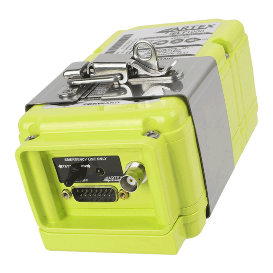
DESCRIPTION, OPERATION, INSTALLATION AND MAINTENANCE MANUAL ELT 1000 (P/N: A3-06-2749-1) B. System Components 1) The ARTEX ELT 1000 housing assembly and tray are made of high impact, fire resistant, polycarbonate-polyester plastic (see Figure 1). Figure 1 ARTEX ELT 1000 Beacon and Mounting Tray 2) The cockpit-mounted remote switch assembly includes a status LED and control switch. -
Page 18: Figure 3 Buzzer
4) The battery pack for the ARTEX ELT 1000 consists of two “D” size Lithium Sulfur Dioxide cells (see Figure 4). Figure 4 Battery Pack Assembly 5) There are 5 antennas that are used with the ARTEX ELT 1000 (see Figure 5). Selection of the proper antenna is dependent upon the application. Figure 5 Antennas Y1-03-0259 Rev. -
Page 19: Operation
2. Operation A. Overview 1) A primary feature of the ARTEX ELT 1000 is its simplicity of operation. 2) A connection jumper (“G-switch loop”) between pins 5 and 12 on the connector enables the G-switch circuitry, allowing activation when the acceleration threshold is exceeded. The jumper is located in the mating connector of the cockpit remote switch wire harness. -
Page 20: Specifications
ARTEX PRODUCTS / ACR ELECTRONICS, INC. DESCRIPTION, OPERATION, INSTALLATION AND MAINTENANCE MANUAL ELT 1000 (P/N: A3-06-2749-1) 3. Specifications A. Environmental and Physical 1) Table 2 lists the environmental and physical specifications of the ELT 1000. CRITERIA PARAMETER CHARACTERISTIC Storage -55°C to +85°C... -
Page 21: Electrical
ARTEX PRODUCTS / ACR ELECTRONICS, INC. DESCRIPTION, OPERATION, INSTALLATION AND MAINTENANCE MANUAL ELT 1000 (P/N: A3-06-2749-1) B. Electrical 1) Table 3 lists the electrical specifications of the ELT 1000. CRITERIA PARAMETER CHARACTERISTIC 406.040 MHz, or higher ± 1 kHz Operating Frequencies 121.5 MHz... -
Page 22: Antenna
15.5 in (394 mm) (Base to Tip) Table 4 Antenna Specifications NOTE: The ARTEX recommended coaxial cables Part No. 611-6013-04 (6 ft) and 611-6013-13 (12 ft) comply with the minimum and maximum cable insertion losses quoted above. Y1-03-0259 Rev. U Company Confidential... -
Page 23: Test And Fault Isolation
NOTE: ARTEX recommends using www.406Test.com to ensure the ELT 1000 is testing through-the-satellite during annual inspections and initial installations. B. Canada 1) CAR Part VI, Standard 625, Appendix C, requires the ELT to be inspected at intervals not exceeding 12 months. -
Page 24: Inspection And Test Procedures
ARTEX PRODUCTS / ACR ELECTRONICS, INC. DESCRIPTION, OPERATION, INSTALLATION AND MAINTENANCE MANUAL ELT 1000 (P/N: A3-06-2749-1) 2. Inspection and Test Procedures A. Checklist 1) Table 5 provides a list of the ELT inspection and testing requirements, a copy of which may be used as a checklist to verify inspection and test completion. -
Page 25: Elt 1000 (P/N: A3-06-2749-1)
ARTEX PRODUCTS / ACR ELECTRONICS, INC. DESCRIPTION, OPERATION, INSTALLATION AND MAINTENANCE MANUAL ELT 1000 (P/N: A3-06-2749-1) E. Battery Pack Inspection – Item 3 CAUTION: THE BATTERY PACK CONTAINS ELECTROSTATIC DISCHARGE SENSITIVE (ESD) COMPONENTS AND, AS SUCH, IT MUST BE HANDLED WITH CARE. IF POSSIBLE, WEAR A GROUNDED WRIST STRAP WHEN HANDLING THE BATTERY PACK DURING INSPECTION AND MAINTENANCE ACTIVITIES. -
Page 26: Performance Test Setup
If the operation time exceeds one hour, an error indicator will be displayed when a self-test is performed (see Self-test section of this document). This does not affect the normal operation of the ELT 1000, but provides an indication to the user that the battery must be replaced, in order to comply with the FAA requirements. -
Page 27: 121.5 Mhz Power Output Measurement - Item 5C
ARTEX PRODUCTS / ACR ELECTRONICS, INC. DESCRIPTION, OPERATION, INSTALLATION AND MAINTENANCE MANUAL ELT 1000 (P/N: A3-06-2749-1) I. 121.5 MHz Power Output Measurement – Item 5c 1) Connect the measuring device, as specified in Figure 6 Performance Test Setup on page 26. -
Page 28: Figure 7 Current Draw Test Setup
ARTEX PRODUCTS / ACR ELECTRONICS, INC. DESCRIPTION, OPERATION, INSTALLATION AND MAINTENANCE MANUAL ELT 1000 (P/N: A3-06-2749-1) 2) Disconnect the battery pack from the ELT. 3) Install test fixture 500-0057 in the power circuit in series between the battery pack connector and the ELT connector (see Figure 7 Current Draw Test Setup). -
Page 29: Digital Message Verification - Item 5G
ELT 1000 (P/N: A3-06-2749-1) M. Digital Message Verification – Item 5g 1) Use a beacon reader, such as ARTEX P/N 453-1000, 453-2000, 8700, or 8701 to test the transmitted digital message. 2) Connect the beacon tester to the ELT, per the instructions of the reader. -
Page 30: Antenna Test - Item 7
ARTEX PRODUCTS / ACR ELECTRONICS, INC. DESCRIPTION, OPERATION, INSTALLATION AND MAINTENANCE MANUAL ELT 1000 (P/N: A3-06-2749-1) NOTE: This test also completes the requirement to check ELT controls by verifying operation of the remote switch. 10) Refer to Table 6 if the LED displays error code flashes. - Page 31 One pulse two seconds long of the local LED, remote light, and buzzer. This pulse is suppressed if problems are found during self-test. Code not used in the ELT 1000 Code not used in the ELT 1000 Low output power...
-
Page 32: Troubleshooting
ARTEX PRODUCTS / ACR ELECTRONICS, INC. DESCRIPTION, OPERATION, INSTALLATION AND MAINTENANCE MANUAL ELT 1000 (P/N: A3-06-2749-1) B. Troubleshooting SYMPTOM PROBABLE CAUSE POSSIBLE SOLUTION Improper wiring Verify wiring Remote switch LED always on Short circuit Verify integrity of all crimp and... -
Page 33: Removal
ARTEX PRODUCTS / ACR ELECTRONICS, INC. DESCRIPTION, OPERATION, INSTALLATION AND MAINTENANCE MANUAL ELT 1000 (P/N: A3-06-2749-1) REMOVAL 1. ELT A. ELT Removal 1) See Figure 9 ELT Removal Sequence. Figure 9 ELT Removal Sequence 2) Disconnect the antenna coax cable. -
Page 34: Battery
ARTEX PRODUCTS / ACR ELECTRONICS, INC. DESCRIPTION, OPERATION, INSTALLATION AND MAINTENANCE MANUAL ELT 1000 (P/N: A3-06-2749-1) Figure 10 Metal Strap Opening 5) Slide the ELT up and out, and away from the mounting tray. 2. Battery A. Battery Removal CAUTION: THE BATTERY PACK CONTAINS ELECTROSTATIC DISCHARGE (ESD) SENSITIVE COMPONENTS AND IT MUST BE HANDLED WITH CARE. -
Page 35: Material Or Equipment Return
ARTEX PRODUCTS / ACR ELECTRONICS, INC. DESCRIPTION, OPERATION, INSTALLATION AND MAINTENANCE MANUAL ELT 1000 (P/N: A3-06-2749-1) Figure 11 Battery Pack Removal 2) Lay the ELT on a surface with the battery side up, to view the embossed text “BATTERY ACCESS ON THIS SIDE”. -
Page 36: Return Material Authorization
ARTEX PRODUCTS / ACR ELECTRONICS, INC. DESCRIPTION, OPERATION, INSTALLATION AND MAINTENANCE MANUAL ELT 1000 (P/N: A3-06-2749-1) B. Return Material Authorization 1) Upon receipt of such notice, ACR Electronics, Inc. will issue a Return Material Authorization (RMA) number which then authorizes return of the material or equipment to the following address: Repair and Overhaul ACR Electronics, Inc. -
Page 37: Installation
ARTEX PRODUCTS / ACR ELECTRONICS, INC. DESCRIPTION, OPERATION, INSTALLATION AND MAINTENANCE MANUAL ELT 1000 (P/N: A3-06-2749-1) INSTALLATION 1. Regulatory Requirements and Guidelines A. For US Registered aircraft: WARNING: FAILURE TO REGISTER THIS ELT WITH NOAA BEFORE INSTALLATION COULD RESULT IN A MONETARY FORFEITURE BEING ISSUED TO THE OWNER. -
Page 38: Rtca
ARTEX PRODUCTS / ACR ELECTRONICS, INC. DESCRIPTION, OPERATION, INSTALLATION AND MAINTENANCE MANUAL ELT 1000 (P/N: A3-06-2749-1) F. RTCA 1) DO-204A, § 3.1.8 guidelines for mounting an ELT: a) The ELT unit shall be mounted to primary aircraft load-carrying structures, such as trusses, bulkheads,... -
Page 39: Mounting Tray
Statistics show that the tail section of an airplane is likely to be less damaged during a crash; therefore, providing a good mounting environment for the ELT. Figure 12 ARTEX ELT 1000 Outline & Dimensions Y1-03-0259 Rev. U Company Confidential... -
Page 40: Figure 13 Elt 1000 Metal Strap Minimum Clearance Dimensions
Figure 13 ELT 1000 Metal Strap Minimum Clearance Dimensions 1) Select a suitable location for the ELT mounting tray (see Figure 12 ARTEX ELT 1000 Outline & Dimensions on page 39 and Figure 13 ELT 1000 Metal Strap Minimum Clearance Dimensions above). -
Page 41: Installation
ARTEX PRODUCTS / ACR ELECTRONICS, INC. DESCRIPTION, OPERATION, INSTALLATION AND MAINTENANCE MANUAL ELT 1000 (P/N: A3-06-2749-1) B. Installation 1) See Figure 14 Typical Mounting Tray Installation. 2) Install the necessary mounting structure as appropriate. 3) Align the mounting tray (A3-06-2758-1) on the mounting structure, such that the arrow on the tray is within 10°... -
Page 42: Antenna
3. Antenna A. General 1) Use only antennas approved for use with the ARTEX ELT 1000. The ELT will not work properly without being connected to an antenna for which it was designed. 2) Verify the antenna selected matches the requirements of the specific installation. Considerations include aircraft maximum rated speed, location restrictions, and any other considerations specific to the installation. -
Page 43: Figure 15 Rod Antenna 110-338, 110-338-01 And A3-06-2835 Outlines And Dimensions
ARTEX PRODUCTS / ACR ELECTRONICS, INC. DESCRIPTION, OPERATION, INSTALLATION AND MAINTENANCE MANUAL ELT 1000 (P/N: A3-06-2749-1) 3) Install a ground plane if necessary. Composite or wood airframes and fabric covered may require a ground plane. 4) Drill the antenna mounting holes and coax connector hole referring to the appropriate antenna illustration for hole patterns and hole sizes. -
Page 44: Remote Switch
A. Location NOTE: The ELT 1000 can be installed using either a 5-wire remote switch, ARTEX P/N 345-6196, or a 2-wire remote switch, ARTEX P/N A3-06-2759. Note that the 2-wire remote switch does not require a connection to the aircraft power to operate. -
Page 45: Buzzer
ARTEX PRODUCTS / ACR ELECTRONICS, INC. DESCRIPTION, OPERATION, INSTALLATION AND MAINTENANCE MANUAL ELT 1000 (P/N: A3-06-2749-1) 5. Buzzer A. Location CAUTION: PLACING THE BUZZER IN THE COCKPIT IS NOT RECOMMENDED DUE TO THE POTENTIAL FOR DISTRACTION. THE BUZZER PRODUCES A LOUD, SIREN-TYPE SOUND WHEN THE ELT IS ACTIVATED. -
Page 46: Wiring
ARTEX PRODUCTS / ACR ELECTRONICS, INC. DESCRIPTION, OPERATION, INSTALLATION AND MAINTENANCE MANUAL ELT 1000 (P/N: A3-06-2749-1) 6. Wiring A. General Considerations and Recommendations CAUTION: IF GROUND OR OTHER CONNECTIONS ARE BROKEN OR OTHERWISE DAMAGED, THE ELT IS STILL CAPABLE OF AUTOMATIC ACTIVATION; HOWEVER, THE COCKPIT REMOTE SWITCH MAY BE INCAPABLE OF RESETTING THE ELT AND OPERATION MAY NOT BE INDICATED ON THE REMOTE SWITCH LED. -
Page 47: Figure 21 Typical 2-Wire Installation For Shielded Harness
ARTEX PRODUCTS / ACR ELECTRONICS, INC. DESCRIPTION, OPERATION, INSTALLATION AND MAINTENANCE MANUAL ELT 1000 (P/N: A3-06-2749-1) Figure 21 Typical 2-Wire Installation for Shielded Harness Y1-03-0259 Rev. U Company Confidential Page 47 of 62... -
Page 48: Figure 22 Typical 5-Wire Installations For Metal Airframes
ARTEX PRODUCTS / ACR ELECTRONICS, INC. DESCRIPTION, OPERATION, INSTALLATION AND MAINTENANCE MANUAL ELT 1000 (P/N: A3-06-2749-1) Figure 22 Typical 5-Wire Installations for Metal Airframes Y1-03-0259 Rev. U Company Confidential Page 48 of 62... -
Page 49: Figure 23 Typical 5-Wire Installations For Composite Airframes
ARTEX PRODUCTS / ACR ELECTRONICS, INC. DESCRIPTION, OPERATION, INSTALLATION AND MAINTENANCE MANUAL ELT 1000 (P/N: A3-06-2749-1) Figure 23 Typical 5-Wire Installations for Composite Airframes Y1-03-0259 Rev. U Company Confidential Page 49 of 62... -
Page 50: Remote Switch Harness Fabrication
ARTEX PRODUCTS / ACR ELECTRONICS, INC. DESCRIPTION, OPERATION, INSTALLATION AND MAINTENANCE MANUAL ELT 1000 (P/N: A3-06-2749-1) B. Remote Switch Harness Fabrication 1) See Figure 24 Remote Switch Harness Arrangement. 2) Allow enough slack to provide a drip loop at the ELT end and a service loop at the cockpit remote switch end. -
Page 51: Elt 1000 (P/N: A3-06-2749-1)
ARTEX PRODUCTS / ACR ELECTRONICS, INC. DESCRIPTION, OPERATION, INSTALLATION AND MAINTENANCE MANUAL ELT 1000 (P/N: A3-06-2749-1) C. ELT D-Sub Plug Installation 1) See Figure 25 Harness Plug Assembly. 2) Select a rubber grommet, supplied as part of the D-Sub housing kit (150-1127), that fits snugly around the harness wiring. -
Page 52: Cockpit Remote Switch 9-Pin Plug Installation
ARTEX PRODUCTS / ACR ELECTRONICS, INC. DESCRIPTION, OPERATION, INSTALLATION AND MAINTENANCE MANUAL ELT 1000 (P/N: A3-06-2749-1) Figure 25 Harness Plug Assembly D. Cockpit Remote Switch 9-Pin Plug Installation 1) Insert the wiring pins into the Molex 9-pin cockpit remote switch plug. Refer to Figure 20 Typical 2-Wire... -
Page 53: Airframe Ground Connections
1) ELTs that are serialized with LONG Cospas-Sarsat protocol will receive external navigation data if available. 2) ELTs programmed with SHORT Cospas-Sarsat protocol will not accept navigation data. 3) When the ELT 1000 is programmed with 4800 baud it will only accept NMEA, and when programmed with 9600 baud it will only accept Aviation Protocol. -
Page 54: Figure 27 Metal Strap Closing
ARTEX PRODUCTS / ACR ELECTRONICS, INC. DESCRIPTION, OPERATION, INSTALLATION AND MAINTENANCE MANUAL ELT 1000 (P/N: A3-06-2749-1) 2) Insert the ELT into the mounting tray at an angle, engaging the locking ears at the tail end first. Press the ELT down until it is fully seated in the mounting tray. -
Page 55: Harness Elt D-Sub Plug Sealing
ARTEX PRODUCTS / ACR ELECTRONICS, INC. DESCRIPTION, OPERATION, INSTALLATION AND MAINTENANCE MANUAL ELT 1000 (P/N: A3-06-2749-1) B. Harness ELT D-Sub Plug Sealing 1) After system operation is verified, with no errors displayed, it is suggested that the harness connector to the ELT be sealed against moisture. -
Page 56: Figure 28 Battery Pack Installation
ARTEX PRODUCTS / ACR ELECTRONICS, INC. DESCRIPTION, OPERATION, INSTALLATION AND MAINTENANCE MANUAL ELT 1000 (P/N: A3-06-2749-1) Figure 28 Battery Pack Installation 3) Verify the gasket is in place and in good condition. Note that the gasket fits only one way in the groove. -
Page 57: Illustrated Parts List
2. Manufacturer Name and Address A. Ordering Information 1) Parts may be ordered from ACR Electronics, Inc., or any authorized dealer. CONTACT INFORMATION: Sales, ACR Electronics, Inc. / ARTEX Products 5757 Ravenswood Rd Fort Lauderdale, FL 33312-6645 USA Phone: (954) 981-3333 Fax: (954) 983-5087 Y1-03-0259 Rev. -
Page 58: Figure 29 Elt 1000 Main Assembly And Installation
ARTEX PRODUCTS / ACR ELECTRONICS, INC. DESCRIPTION, OPERATION, INSTALLATION AND MAINTENANCE MANUAL ELT 1000 (P/N: A3-06-2749-1) Figure 29 ELT 1000 Main Assembly and Installation ITEM PART # DESCRIPTION A3-06-2749-1 ARTEX ELT 1000 Final Assembly A3-06-2748-1 ARTEX ELT 1000 Main Assembly... -
Page 59: Figure 30 Harness Components
ARTEX PRODUCTS / ACR ELECTRONICS, INC. DESCRIPTION, OPERATION, INSTALLATION AND MAINTENANCE MANUAL ELT 1000 (P/N: A3-06-2749-1) Figure 30 Harness Components ITEM PART # DESCRIPTION A3-06-2759 Switch, cockpit remote 201-0408 Screw, PHL, 4-40 x ¼”, SS 247-0400 Washer, internal lock, SS, #4 241-0440 Nut, 4-40 x ¼”, hex, SS... -
Page 60: Figure 31 Antennas
ARTEX PRODUCTS / ACR ELECTRONICS, INC. DESCRIPTION, OPERATION, INSTALLATION AND MAINTENANCE MANUAL ELT 1000 (P/N: A3-06-2749-1) Figure 31 Antennas ITEM PART # DESCRIPTION 110-338-01 Antenna, Rod, CI317-1 (black single input) 110-773 Antenna, 121.5/406 MHz, whip 110-340 Antenna, Blade A3-06-2835 Antenna, Rod, CI315-1 (white single input) -
Page 61: Appendix A - Elt Registration
2) Specific registration web sites and information may be found at: a) The ARTEX products web site at www.acrartex.com, which has links to on-line registration sites and also a link to registration forms and instructions for a number of countries. - Page 62 ARTEX PRODUCTS / ACR ELECTRONICS, INC. DESCRIPTION, OPERATION, INSTALLATION AND MAINTENANCE MANUAL ELT 1000 (P/N: A3-06-2749-1) NOTE: NOAA may also be contacted by mail at: SARSAT Beacon Registration NSOF, E/SPO53 1315 East West Hwy Silver Spring, MD 20910-9684 or by phone at 1-888-212-7283 or 301-817-4565.
Need help?
Do you have a question about the ELT 1000 and is the answer not in the manual?
Questions and answers
how can i get the wiring manual for the ELT 1000 ME 406 connector
The wiring manual for the ARTEX ELT 1000, including connector details, is included in the "Description, Operation, Installation and Maintenance Manual" for the ELT 1000. This manual contains wiring diagrams such as:
- Typical 2-Wire Installation for Unshielded and Shielded Harness (Figures 20–21)
- Typical 5-Wire Installations for Metal and Composite Airframes (Figures 22–23)
- Remote Switch Harness Arrangement (Figure 24)
- Harness Plug Assembly (Figure 25)
To obtain the manual, refer to the ELT 1000 manual (P/N A3-06-2749-1).
This answer is automatically generated