ARTEX G406-4 Operation, Installation, And Maintenance Manual
Emergency locator transmitter
Hide thumbs
Also See for G406-4:
Table of Contents
Advertisement
EMERGENCY LOCATOR TRANSMITTER
Description, Operation, Installation and Maintenance Manual
This manual includes data for the equipment that follows:
Component
Emergency Locator Transmitter
G406-4
Part No.
453-5012
25-62-21
ARTEX PRODUCTS / ACR ELECTRONICS, INC.
Model No.
G406-4
Initial Issue JAN 08/2001
5757 Ravenswood Rd, Ft. Lauderdale, FL 33312
Page 1 of 69
Dec 01/14
570-5012 Rev. K
Cage Code: 18560
Advertisement
Table of Contents
Troubleshooting

Related Manuals for ARTEX G406-4


Summary of Contents for ARTEX G406-4
- Page 1 Component Part No. Model No. Emergency Locator Transmitter 453-5012 G406-4 Page 1 of 69 25-62-21 Dec 01/14 570-5012 Rev. K Initial Issue JAN 08/2001 ARTEX PRODUCTS / ACR ELECTRONICS, INC. 5757 Ravenswood Rd, Ft. Lauderdale, FL 33312 Cage Code: 18560...
- Page 2 ARTEX PRODUCTS / ACR ELECTRONICS, INC DESCRIPTION, OPERATION, INSTALLATION AND MAINTENANCE MANUAL G406-4 (453-5012) PROPRIETARY INFORMATION This document contains proprietary information and such information may not be disclosed to others for any purpose, nor used for manufacturing purposes without written permission from ACR Electronics.
-
Page 3: Record Of Revisions
ARTEX PRODUCTS / ACR ELECTRONICS, INC DESCRIPTION, OPERATION, INSTALLATION AND MAINTENANCE MANUAL G406-4 (453-5012) RECORD OF REVISIONS REVISION CHANGE DATE REVISION CHANGE DATE RELEASE Jan 14/2000 DCN 1589 Feb 12/2001 DCN 1604 Mar 13/2001 DCN 1641 Apr 11/2001 DCN 1712... -
Page 4: Service Bulletin List
ARTEX PRODUCTS / ACR ELECTRONICS, INC DESCRIPTION, OPERATION, INSTALLATION AND MAINTENANCE MANUAL G406-4 (453-5012) SERVICE BULLETIN LIST SERVICE ISSUE MANUAL MANUAL SUBJECT BULLETIN NO DATE REV NO REV DATE 25-62-21 Page 4 of 69 Dec 01/14... -
Page 5: List Of Effective Pages
ARTEX PRODUCTS / ACR ELECTRONICS, INC DESCRIPTION, OPERATION, INSTALLATION AND MAINTENANCE MANUAL G406-4 (453-5012) LIST OF EFFECTIVE PAGES SUBJECT PAGE DATE SUBJECT PAGE DATE Title Page Aug 13/14 Test and Fault Isolation (cont.) Aug 13/14 Notices Aug 13/14 Aug 13/14... - Page 6 ARTEX PRODUCTS / ACR ELECTRONICS, INC DESCRIPTION, OPERATION, INSTALLATION AND MAINTENANCE MANUAL G406-4 (453-5012) SUBJECT PAGE DATE SUBJECT PAGE DATE Installation (cont.) Aug 13/14 Appendix A Aug 13/14 Aug 13/14 Aug 13/14 Aug 13/14 Illustrated Parts List Aug 13/14 Aug 13/14...
-
Page 7: Table Of Contents
ARTEX PRODUCTS / ACR ELECTRONICS, INC DESCRIPTION, OPERATION, INSTALLATION AND MAINTENANCE MANUAL G406-4 (453-5012) TABLE OF CONTENTS RECORD OF REVISIONS ..........................3 SERVICE BULLETIN LIST ........................... 4 LIST OF EFFECTIVE PAGES........................5 TABLE OF CONTENTS ..........................7 LIST OF FIGURES ........................... 10 INTRODUCTION ............................. - Page 8 ARTEX PRODUCTS / ACR ELECTRONICS, INC DESCRIPTION, OPERATION, INSTALLATION AND MAINTENANCE MANUAL G406-4 (453-5012) Inspection and Test Procedures ....................27 Checklist ..........................27 Preparation .......................... 28 Coax Cables and Wiring Connections Inspection – Item 1 ............28 Mounting Tray and Hardware Inspection – Item 2 ..............28 Battery Pack Inspection –...
- Page 9 ARTEX PRODUCTS / ACR ELECTRONICS, INC DESCRIPTION, OPERATION, INSTALLATION AND MAINTENANCE MANUAL G406-4 (453-5012) Installation .......................... 50 Wiring ............................51 General Considerations and Recommendations ..............51 Remote Switch Harness Fabrication ..................52 ELT 12-Pin Receptacle Installation ..................54 Cockpit Remote Switch 9-Pin Plug Installation ................ 55 Wiring Installation ........................
-
Page 10: List Of Figures
DESCRIPTION, OPERATION, INSTALLATION AND MAINTENANCE MANUAL G406-4 (453-5012) LIST OF FIGURES Figure 1 G406-4 ELT and Mounting Frame Assembly ................19 Figure 2 Remote Switch Front View ....................19 Figure 3 Buzzer ..........................20 Figure 4 Battery Pack Assembly ......................20 Figure 5 Antennas .......................... -
Page 11: Introduction
(ELT). This information is provided to ensure initial and continued airworthiness. Information presented in this manual is accurate at time of printing, but is subject to change. Refer to the Artex products web site at www.acrelectronics.com for the latest information and any updates to this manual. -
Page 12: Model Description
SUBTASK 25-62-21-990-001 A. G406-4 1) The G406-4 is a type AF (Automatic Fixed) ELT, which transmits on 121.5, 243.0, and 406 MHz. 2) The ELT is enclosed within a multi-piece mounting frame consisting of a mounting tray, protective top cover and mounting frame cap. -
Page 13: Rtca Do-160D Compliance
ARTEX PRODUCTS / ACR ELECTRONICS, INC DESCRIPTION, OPERATION, INSTALLATION AND MAINTENANCE MANUAL G406-4 (453-5012) SUBTASK 25-62-21-990-003 C. RTCA DO-160D Compliance 1) DO-160D Environmental Categories: C1-BA204XRXXXXXZAZZ204BXXX 2) The DO-160D environmental categories breakdown is detailed in Table 1. CATEGORY SECTION DESCRIPTION Temperature/Altitude 4.5.4... -
Page 14: Frequency Allocations
SUBTASK 25-62-21-990-002 B. Discussion 1) The 406 MHz transmitter frequency of the G406-4 ELT was originally 406.025 MHz. In order to comply with COSPAS-SARSAT frequency allocation requirements, changes to the 406 MHz frequency may occur since the original release of this product. -
Page 15: List Of Acronyms, Abbreviations, And Definitions
ARTEX PRODUCTS / ACR ELECTRONICS, INC DESCRIPTION, OPERATION, INSTALLATION AND MAINTENANCE MANUAL G406-4 (453-5012) TASK 25-62-21-990-805 5. List of Acronyms, Abbreviations, and Definitions SUBTASK 25-62-21-990-001 Term Definition Advisory Circular – A Federal Aviation Administration (USA) bulletin with special information. For the purposes of this document, the acronym AC does not refer to electrical alternating current. - Page 16 ARTEX PRODUCTS / ACR ELECTRONICS, INC DESCRIPTION, OPERATION, INSTALLATION AND MAINTENANCE MANUAL G406-4 (453-5012) FSDO Flight Standards District Office – FAA district offices responsible for aircraft certification, operation, maintenance, and modification issues, approvals and enforcement. G-Switch A velocity switch that detects sudden de-acceleration and is used to automatically activate an ELT.
-
Page 17: References
Transmitters (ELT)” SUBTASK 25-62-21-990-002 B. Other Documents 1) The following documents are available on-line at the Artex products web site at www.acrelectronics.com, or from ACR Electronics upon request. a) 570-1000, “ELT Test Set (ETS) Operation Manual” b) 570-4602, “ELT/NAV Interface Description, Operation, Installation and Maintenance Manual”... -
Page 18: Description And Operation
ARTEX PRODUCTS / ACR ELECTRONICS, INC DESCRIPTION, OPERATION, INSTALLATION AND MAINTENANCE MANUAL G406-4 (453-5012) DESCRIPTION AND OPERATION TASK 25-62-21-870-801 1. Description SUBTASK 25-62-21-870-001 A. Functional Overview 1) The ELT automatically activates during a crash and transmits the standard sweep tone on 121.5 and 243.0 MHz. -
Page 19: Components
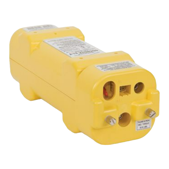
SUBTASK 25-62-21-870-002 B. Components 1) The G406-4 ELT main assembly is housed in a high impact, fire resistant, polycarbonate plastic case, which is enclosed in a protective mounting frame assembly made of similar material. See Figure 1 G406-4 ELT and Mounting Frame Assembly. -
Page 20: Figure 3 Buzzer
Figure 3 Buzzer 4) The battery pack for the G406-4 ELT consists of four “D” size lithium manganese dioxide cells connected in series. In an effort to increase the safety of the battery pack, a number of features were designed into the battery pack. -
Page 21: Operation
1) See Figure 6 ELT Operational Flow Diagram. 2) A primary feature of the G406-4 ELT is its simplicity of operation. As long as the ELT is connected to the remote switch harness ELT connector, such that pins 5 and 8 are jumpered (G-switch loop), it will activate in the event of a crash. -
Page 22: Normal Operation
ARTEX PRODUCTS / ACR ELECTRONICS, INC DESCRIPTION, OPERATION, INSTALLATION AND MAINTENANCE MANUAL G406-4 (453-5012) 6) A warning buzzer is required under C126 TSO approval. The buzzer is powered by the ELT and therefore not dependent upon the aircraft battery for operation. It is not designed to operate continuously, but sounds at predetermined intervals and runs for shorter periods toward the end of ELT battery life. -
Page 23: Specifications
TASK 25-62-21-870-803 3. Specifications SUBTASK 25-62-21-870-001 A. Environmental and Physical 1) Table 2 lists the environmental and physical specifications of the G406-4 ELT. NOTE: For automatic activation, the higher threshold of 4.5 ft/sec (2.3 ) is specified in accordance with Eurocae ED-62. Use of the higher threshold crash sensor has been approved by the FAA as a deviation to TSO C126 (FAA Reference #98-130S-108, February 6, 1998). -
Page 24: Electrical
ARTEX PRODUCTS / ACR ELECTRONICS, INC DESCRIPTION, OPERATION, INSTALLATION AND MAINTENANCE MANUAL G406-4 (453-5012) SUBTASK 25-62-21-870-002 B. Electrical 1) Table 3 lists the electrical specifications of the G406-4 ELT. CRITERIA PARAMETER CHARACTERISTIC ± 2 KHz (Initial) 406.025 MHz ± 5 KHz (5 years) -
Page 25: Antennas
ARTEX PRODUCTS / ACR ELECTRONICS, INC DESCRIPTION, OPERATION, INSTALLATION AND MAINTENANCE MANUAL G406-4 (453-5012) SUBTASK 25-62-21-870-003 C. Antennas 1) Table 4 lists the specifications of the antennas approved for use with the G406-4 ELT. CHARACTERISTIC PARAMETERS 110-320 110-324 110-329 Style... -
Page 26: Test And Fault Isolation
ARTEX PRODUCTS / ACR ELECTRONICS, INC DESCRIPTION, OPERATION, INSTALLATION AND MAINTENANCE MANUAL G406-4 (453-5012) TEST AND FAULT ISOLATION TASK 25-62-21-750-801 1. Inspection and Test Regulatory Requirements SUBTASK 25-62-21-990-001 A. United States 1) In accordance with FAR Part 91, Subpart C, § 91.207 (d), the ELT must be inspected within 12 calendar months after the last inspection for: a) Proper installation;... -
Page 27: Inspection And Test Procedures
ARTEX PRODUCTS / ACR ELECTRONICS, INC DESCRIPTION, OPERATION, INSTALLATION AND MAINTENANCE MANUAL G406-4 (453-5012) TASK 25-62-21-750-802 2. Inspection and Test Procedures SUBTASK 25-62-21-990-001 A. Checklist 1) Table 5 provides a list of the ELT inspection and testing requirements, a copy of which may be used as a checklist to verify inspection and test completion. -
Page 28: Preparation
ARTEX PRODUCTS / ACR ELECTRONICS, INC DESCRIPTION, OPERATION, INSTALLATION AND MAINTENANCE MANUAL G406-4 (453-5012) SUBTASK 25-62-21-000-001 B. Preparation 1) Remove the ELT in accordance with SUBTASK 25-62-21-010-001 on page 39. 2) Remove the battery pack in accordance with SUBTASK 25-62-21-050-001 on page 40. -
Page 29: G-Switch Functional Check - Item 4
ARTEX PRODUCTS / ACR ELECTRONICS, INC DESCRIPTION, OPERATION, INSTALLATION AND MAINTENANCE MANUAL G406-4 (453-5012) SUBTASK 25-62-21-750-001 F. G-Switch Functional Check – Item 4 CAUTION: A JUMPER IS REQUIRED TO PERFORM THIS CHECK. DUE TO THE POTENTIAL OF PHYSICAL DAMAGE IF THE JUMPER IS IMPROPERLY INSTALLED, THIS STEP SHOULD ONLY BE PERFORMED BY AN EXPERIENCED TECHNICIAN/MECHANIC. -
Page 30: Performance Testing Setup
ARTEX PRODUCTS / ACR ELECTRONICS, INC DESCRIPTION, OPERATION, INSTALLATION AND MAINTENANCE MANUAL G406-4 (453-5012) SUBTASK 25-62-21-750-002 G. Performance Testing Setup NOTE: The ELT software routine logs battery life in 30-second increments. A minimum of 30 seconds is added to the battery usage total each time the ELT is activated and de-activated. -
Page 31: 121.5/243.0 Mhz Power Output Measurement - Item 5C
ARTEX PRODUCTS / ACR ELECTRONICS, INC DESCRIPTION, OPERATION, INSTALLATION AND MAINTENANCE MANUAL G406-4 (453-5012) SUBTASK 25-62-21-750-005 J. 121.5/243.0 MHz Power Output Measurement – Item 5c 1) Connect the measuring device, referring to SUBTASK 25-62-21-750-002 on page 30. 2) Activate the ELT, if necessary, by placing the control switch in the “ON” position. -
Page 32: Current Draw Test - Item 5F
ARTEX PRODUCTS / ACR ELECTRONICS, INC DESCRIPTION, OPERATION, INSTALLATION AND MAINTENANCE MANUAL G406-4 (453-5012) SUBTASK 25-62-21-750-008 M. Current Draw Test – Item 5f CAUTION: EXERCISE EXTREME CAUTION TO AVOID CAUSING A SHORT CIRCUIT CONDITION, WHICH WILL BLOW THE FUSES IN THE BATTERY PACK. THIS TEST SHOULD ONLY BE PERFORMED BY AN EXPERIENCED TECHNICIAN/MECHANIC. -
Page 33: Digital Message Verification - Item 5G
ARTEX PRODUCTS / ACR ELECTRONICS, INC DESCRIPTION, OPERATION, INSTALLATION AND MAINTENANCE MANUAL G406-4 (453-5012) SUBTASK 25-62-21-750-009 N. Digital Message Verification – Item 5g 1) Activate the ELT by placing the control switch in the “ON” position. 2) Allow the ELT to transmit for 15 to 30 seconds, but not more than 40 seconds. -
Page 34: Installed Transmitter Test - Item 6
ARTEX PRODUCTS / ACR ELECTRONICS, INC DESCRIPTION, OPERATION, INSTALLATION AND MAINTENANCE MANUAL G406-4 (453-5012) SUBTASK 25-62-21-750-011 P. Installed Transmitter Test – Item 6 CAUTION: DO NOT ALLOW THE DURATION OF THIS TEST TO EXCEED 5 SECONDS. THE ELT WILL TRANSMIT A 406 MHZ SIGNAL AFTER THE ELT IS ACTIVATED FOR APPROXIMATELY 47 SECONDS. -
Page 35: Antenna Test - Item 7
ARTEX PRODUCTS / ACR ELECTRONICS, INC DESCRIPTION, OPERATION, INSTALLATION AND MAINTENANCE MANUAL G406-4 (453-5012) SUBTASK 25-62-21-750-012 Q. Antenna Test – Item 7 CAUTION: DO NOT ALLOW THE DURATION OF THIS TEST TO EXCEED 5 SECONDS. 1) Tune a low quality AM receiver (i.e., radio) to 121.5 MHz. -
Page 36: Fault Isolation
ARTEX PRODUCTS / ACR ELECTRONICS, INC DESCRIPTION, OPERATION, INSTALLATION AND MAINTENANCE MANUAL G406-4 (453-5012) TASK 25-62-21-810-801 Fault Isolation SUBTASK 25-62-21-810-001 A. Self-Test Error Troubleshooting Guidelines 1) Table 6 describes the ELT self-test LED error codes (i.e., flash codes), their probable causes, and possible solutions. - Page 37 ARTEX PRODUCTS / ACR ELECTRONICS, INC DESCRIPTION, OPERATION, INSTALLATION AND MAINTENANCE MANUAL G406-4 (453-5012) CODE PROBABLE CAUSE POSSIBLE SOLUTION Battery low Low power output 3A fuse on battery pack circuit board faulty 3-Flash (cont.) Improper programming Verify 406 MHz programming...
-
Page 38: Elt Troubleshooting Guidelines
ARTEX PRODUCTS / ACR ELECTRONICS, INC DESCRIPTION, OPERATION, INSTALLATION AND MAINTENANCE MANUAL G406-4 (453-5012) SUBTASK 25-62-21-810-002 B. ELT Troubleshooting Guidelines 1) Table 7 provides ELT troubleshooting guidelines for installation and operational issues. SYMPTOM PROBABLE CAUSE POSSIBLE SOLUTION Improper wiring Verify wiring... -
Page 39: Removal
ARTEX PRODUCTS / ACR ELECTRONICS, INC DESCRIPTION, OPERATION, INSTALLATION AND MAINTENANCE MANUAL G406-4 (453-5012) REMOVAL TASK 25-62-21-010-801 1. ELT SUBTASK 25-62-21-010-001 A. ELT Removal 1) See Figure 10 ELT Removal Sequence. Figure 10 ELT Removal Sequence 2) Loosen the mounting frame cap thumbscrews. -
Page 40: Battery
ARTEX PRODUCTS / ACR ELECTRONICS, INC DESCRIPTION, OPERATION, INSTALLATION AND MAINTENANCE MANUAL G406-4 (453-5012) TASK 25-62-21-050-801 2. Battery SUBTASK 25-62-21-050-001 A. Battery Pack Removal CAUTION: THE BATTERY PACK CONTAINS ELECTROSTATIC DISCHARGE SENSITIVE (ESD) COMPONENTS AND IT MUST BE HANDLED WITH CARE. IF POSSIBLE, WEAR A GROUNDED WRIST STRAP WHEN HANDLING THE BATTERY PACK DURING INSTALLATION ACTIVITIES. -
Page 41: Material Or Equipment Return
ARTEX PRODUCTS / ACR ELECTRONICS, INC DESCRIPTION, OPERATION, INSTALLATION AND MAINTENANCE MANUAL G406-4 (453-5012) TASK 25-62-21-500-801 3. Material or Equipment Return SUBTASK 25-62-21-510-001 A. Shipment Information 1) If any material or equipment is to be returned to the factory, under warranty or otherwise, ACR... -
Page 42: Installation
ARTEX PRODUCTS / ACR ELECTRONICS, INC DESCRIPTION, OPERATION, INSTALLATION AND MAINTENANCE MANUAL G406-4 (453-5012) INSTALLATION TASK 25-62-21-410-801 1. Regulatory Requirements and Guidelines SUBTASK 25-62-21-990-001 A. For US Registered aircraft: WARNING: FAILURE TO REGISTER THIS ELT WITH NOAA BEFORE INSTALLATION COULD RESULT IN A MONETARY FORFEITURE BEING ISSUED TO THE OWNER. -
Page 43: Canada
ARTEX PRODUCTS / ACR ELECTRONICS, INC DESCRIPTION, OPERATION, INSTALLATION AND MAINTENANCE MANUAL G406-4 (453-5012) SUBTASK 25-62-21-990-003 D. Canada 1) All installations must be performed in accordance with Canadian Aviation Regulations (CAR) Part V, Chapter 551, Paragraph 551.104. SUBTASK 25-62-21-990-004 E. Other Countries 1) Installations in aircraft outside of the United States and Canada, must be performed in accordance with applicable regulatory authority rules and regulations. -
Page 44: Mounting Tray
ARTEX PRODUCTS / ACR ELECTRONICS, INC DESCRIPTION, OPERATION, INSTALLATION AND MAINTENANCE MANUAL G406-4 (453-5012) TASK 25-62-21-450-801 2. Mounting Tray SUBTASK 25-62-21-450-001 A. Location CAUTION: MANY ORIGINAL ELT INSTALLATIONS ARE INADEQUATE AS FAR AS UNIT LOCATION AND SURFACE RIGIDITY ARE CONCERNED. BECAUSE OF THE CRITICAL FUNCTION AN ELT PERFORMS, IT IS IMPORTANT THE INSTALLATION FOLLOWS THE INSTRUCTIONS AND RECOMMENDATIONS HEREIN. -
Page 45: Figure 12 G406-4 Elt Outline And Dimensions
DESCRIPTION, OPERATION, INSTALLATION AND MAINTENANCE MANUAL G406-4 (453-5012) 1) Select a suitable location for the ELT mounting tray. See Figure 12 G406-4 ELT Outline and Dimensions. Refer to these dimensions when determining mounting location. Figure 12 G406-4 ELT Outline and Dimensions 2) Locate the mounting tray such that the ELT mounting frame cap has at least 5 inches (127 mm) of clearance for installation and removal. -
Page 46: Installation
4) Mark the four holes needed for mounting the tray, using the tray as a pattern. The hole pattern is also illustrated in Figure 12 G406-4 ELT Outline and Dimensions on page 45. 5) Drill the four mounting holes with a #19 or 4.25 mm drill. -
Page 47: Antenna
SUBTASK 25-62-21-990-001 A. Selection 1) Use only antennas approved for use with the G406-4 ELT. The ELT will not work properly without being connected to an antenna for which it was designed. 2) Verify the antenna selected matches the requirements of the specific installation. Considerations include aircraft maximum rated speed, location restrictions, and any other considerations specific to the installation. -
Page 48: Figure 14 Whip Antennas 110-324 And 110-329 Outlines And Dimensions
ARTEX PRODUCTS / ACR ELECTRONICS, INC DESCRIPTION, OPERATION, INSTALLATION AND MAINTENANCE MANUAL G406-4 (453-5012) Figure 14 Whip Antennas 110-324 and 110-329 Outlines and Dimensions Figure 15 Rod Antenna 110-320 Outline and Dimensions 25-62-21 Page 48 of 69 Dec 01/14... -
Page 49: Remote Switch
ARTEX PRODUCTS / ACR ELECTRONICS, INC DESCRIPTION, OPERATION, INSTALLATION AND MAINTENANCE MANUAL G406-4 (453-5012) TASK 25-62-21-450-803 4. Remote Switch SUBTASK 25-62-21-450-001 A. Location 1) Select a suitable location for the remote switch assembly. The switch assembly must be mounted in the cockpit where the pilot can easily reach the switch and see the LED. -
Page 50: Buzzer
ARTEX PRODUCTS / ACR ELECTRONICS, INC DESCRIPTION, OPERATION, INSTALLATION AND MAINTENANCE MANUAL G406-4 (453-5012) TASK 25-62-21-450-804 5. Buzzer SUBTASK 25-62-21-450-001 A. Location CAUTION: PLACING THE BUZZER IN THE COCKPIT IS NOT RECOMMENDED DUE TO THE POTENTIAL FOR DISTRACTION. THE BUZZER PRODUCES A LOUD, SIREN-TYPE SOUND WHEN THE ELT IS ACTIVATED. -
Page 51: Wiring
ARTEX PRODUCTS / ACR ELECTRONICS, INC DESCRIPTION, OPERATION, INSTALLATION AND MAINTENANCE MANUAL G406-4 (453-5012) TASK 25-62-21-450-805 6. Wiring SUBTASK 25-62-21-990-001 A. General Considerations and Recommendations CAUTION: IF GROUND OR OTHER CONNECTIONS ARE BROKEN OR OTHERWISE DAMAGED, THE ELT IS STILL CAPABLE OF AUTOMATIC ACTIVATION; HOWEVER, THE COCKPIT REMOTE SWITCH MAY BE INCAPABLE OF RESETTING THE ELT AND OPERATION MAY NOT BE INDICATED ON THE REMOTE SWITCH LED. -
Page 52: Remote Switch Harness Fabrication
ARTEX PRODUCTS / ACR ELECTRONICS, INC DESCRIPTION, OPERATION, INSTALLATION AND MAINTENANCE MANUAL G406-4 (453-5012) SUBTASK 25-62-21-450-001 B. Remote Switch Harness Fabrication 1) See Figure 18 Remote Switch Harness Arrangement. Figure 18 Remote Switch Harness Arrangement 2) Fabricate a 5-wire harness long enough to reach from the ELT to the cockpit remote switch, allowing enough slack to provide a drip loop at the ELT end and a service loop at the cockpit remote switch end. -
Page 53: Figure 19 Remote Switch Harness Wiring Diagram
ARTEX PRODUCTS / ACR ELECTRONICS, INC DESCRIPTION, OPERATION, INSTALLATION AND MAINTENANCE MANUAL G406-4 (453-5012) Figure 19 Remote Switch Harness Wiring Diagram 4) Fabricate two wires of sufficient length to reach from the harness ELT receptacle to the buzzer. NOTE: These wires provide power and ground for the buzzer. Use appropriate means of identification for the wires, such that the wires can be readily identified. -
Page 54: Elt 12-Pin Receptacle Installation
ARTEX PRODUCTS / ACR ELECTRONICS, INC DESCRIPTION, OPERATION, INSTALLATION AND MAINTENANCE MANUAL G406-4 (453-5012) SUBTASK 25-62-21-450-002 C. ELT 12-Pin Receptacle Installation 1) Feed the harness wires on the ELT end through the mounting frame cap assembly (452-0228). See Figure 20 Remote Harness Wiring at ELT End. -
Page 55: Cockpit Remote Switch 9-Pin Plug Installation
ARTEX PRODUCTS / ACR ELECTRONICS, INC DESCRIPTION, OPERATION, INSTALLATION AND MAINTENANCE MANUAL G406-4 (453-5012) SUBTASK 25-62-21-450-003 D. Cockpit Remote Switch 9-Pin Plug Installation 1) Inert the wiring pins in the 151-5009 Molex 9-pin cockpit remote switch plug. See Figure 19 Remote Switch Harness Wiring Diagram on page 53. -
Page 56: Airframe Ground Connections
ARTEX PRODUCTS / ACR ELECTRONICS, INC DESCRIPTION, OPERATION, INSTALLATION AND MAINTENANCE MANUAL G406-4 (453-5012) SUBTASK 25-62-21-450-008 I. Airframe Ground Connections 1) Connect the ground wires to the airframe in accordance with the aircraft manufacturer’s written instructions or as described in AC 43.13-1, Chapter 11, § 15, as applicable. See Figure 19 Remote Switch Harness Wiring Diagram on page 53. -
Page 57: Harness Elt Receptacle Sealing
ARTEX PRODUCTS / ACR ELECTRONICS, INC DESCRIPTION, OPERATION, INSTALLATION AND MAINTENANCE MANUAL G406-4 (453-5012) Figure 21 ELT Installation Sequence 2) Verify the ELT local switch is in the “OFF” position. 3) Insert the ELT into the mounting tray at an angle, such that the locking ears at the end opposite the direction-of-flight arrow fit into the mounting tray locking slots. -
Page 58: Installation Documentation
ARTEX PRODUCTS / ACR ELECTRONICS, INC DESCRIPTION, OPERATION, INSTALLATION AND MAINTENANCE MANUAL G406-4 (453-5012) SUBTASK 25-62-21-410-002 C. Installation Documentation 1) Make appropriate logbook (i.e., aircraft records) entries and submit FAA Form 337, along with any supporting data required by the FAA for approval of the installation, as applicable. -
Page 59: Figure 23 Battery Pack Retaining Screw Tightening Pattern
ARTEX PRODUCTS / ACR ELECTRONICS, INC DESCRIPTION, OPERATION, INSTALLATION AND MAINTENANCE MANUAL G406-4 (453-5012) 3) Apply a thin coating of non-petroleum based silicone grease, such as GE G-635, to the rubber seal to facilitate installation and allow the ELT and battery pack to slide together without binding on the rubber seal. -
Page 60: New Battery Installation
ARTEX PRODUCTS / ACR ELECTRONICS, INC DESCRIPTION, OPERATION, INSTALLATION AND MAINTENANCE MANUAL G406-4 (453-5012) SUBTASK 25-62-21-450-002 B. New Battery Installation CAUTION: DO NOT USE CONTACT CLEANER ON ELT COMPONENTS. SUCH CHEMICAL AGENTS CAN BE HIGHLY DESTRUCTIVE TO THE MOUNTING HARDWARE AND ELT HOUSING, CAUSING CRACKING, FRACTURING AND OTHER DAMAGE. -
Page 61: Appendix A - Elt Registration
ARTEX PRODUCTS / ACR ELECTRONICS, INC DESCRIPTION, OPERATION, INSTALLATION AND MAINTENANCE MANUAL G406-4 (453-5012) APPENDIX A – ELT REGISTRATION TASK 25-62-21-990-801 1. Background Information SUBTASK 25-62-21-990-001 A. Hex ID Code 1) Each 406 MHz ELT is programmed with a unique hex ID code (i.e., registration code) that is transmitted to the SAR satellite system. -
Page 62: Registration
1) In the United States, the National Oceanic and Atmospheric Administration (NOAA) is the registration agency. 2) Specific registration web sites and information may be found at: a) The Artex products web site at www.acrartex.com has links to online registration sites and also a link to registration forms and instructions for a number of countries. -
Page 63: Illustrated Parts List
SUBTASK 25-62-21-990-001 A. Ordering Information 1) Approved parts may be ordered from ACR Electronics, or any authorized dealer. CONTACT INFORMATION Sales, ACR Electronics, Inc / Artex Products 5757 Ravenswood Rd Fort Lauderdale, FL 33312-6645, USA Phone: (954) 981-3333 Fax: (954) 983-5087... -
Page 64: Explanation Of Detailed Parts List Entries
ARTEX PRODUCTS / ACR ELECTRONICS, INC DESCRIPTION, OPERATION, INSTALLATION AND MAINTENANCE MANUAL G406-4 (453-5012) TASK 25-62-21-990-803 3. Explanation of Detailed Parts List Entries SUBTASK 25-62-21-990-001 A. Fig # & Item Column 1) The first number at the top of the column is the figure number of the corresponding illustration. -
Page 65: Upa (Units Per Assembly) Column
ARTEX PRODUCTS / ACR ELECTRONICS, INC DESCRIPTION, OPERATION, INSTALLATION AND MAINTENANCE MANUAL G406-4 (453-5012) 3) Assemblies, subassemblies, and detail parts subject to modification, deletion, addition, or replacement by an issued service bulletin, are annotated to indicate both pre- and post-service bulletin configurations. The term (PRE SB XXXX) in the “Nomenclature”... -
Page 66: Detailed Parts List
ARTEX PRODUCTS / ACR ELECTRONICS, INC DESCRIPTION, OPERATION, INSTALLATION AND MAINTENANCE MANUAL G406-4 (453-5012) TASK 25-62-21-990-804 4. Detailed Parts List Figure 24 G406-4 ELT Main Assembly and Installation FIG # ITEM PART # 1234 NOMENCLATURE Figure Protective Top Cover Assembly, Yellow... - Page 67 ARTEX PRODUCTS / ACR ELECTRONICS, INC DESCRIPTION, OPERATION, INSTALLATION AND MAINTENANCE MANUAL G406-4 (453-5012) FIG # ITEM PART # 1234 NOMENCLATURE G406-4 Main Assembly 453-5012 – 591-0999 . Label, Hex Code – 591-0429 . Label, Country Code . 406 Lithium Battery Pack, Yellow...
-
Page 68: Figure 25 Electrical Components
ARTEX PRODUCTS / ACR ELECTRONICS, INC DESCRIPTION, OPERATION, INSTALLATION AND MAINTENANCE MANUAL G406-4 (453-5012) Figure 25 Electrical Components FIG # PART # 1234 NOMENCLATURE Figure Switch, Cockpit Remote 345-6196-04 ATTACHING PARTS – 201-0408 Screw, PHP 4-40 x 1/4” SS –... -
Page 69: Figure 26 Antennas
ARTEX PRODUCTS / ACR ELECTRONICS, INC DESCRIPTION, OPERATION, INSTALLATION AND MAINTENANCE MANUAL G406-4 (453-5012) Figure 26 Antennas FIG # ITEM PART # 1234 NOMENCLATURE Figure Antenna, Whip (121.5/243.0 MHz) 110-324 Antenna, Whip (406 MHz) 110-329 Antenna, Tri-Band Rod (Dual Input) 110-320 .
Need help?
Do you have a question about the G406-4 and is the answer not in the manual?
Questions and answers