Table of Contents
Advertisement
Quick Links
User manual for
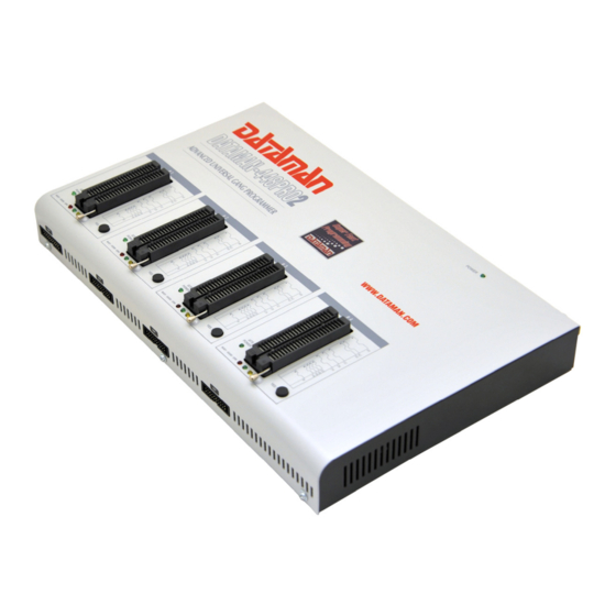
DATAMAN-448PRO2
Super fast universal 4x 48-pindrive concurrent multiprogramming system with ISP capability
DATAMAN-48PRO2
Super fast universal 48-pindrive Programmer with USB/LPT interface and ISP capability
DATAMAN-48PRO2C
Super fast universal 48-pindrive Programmer with USB interface and ISP capability
DATAMAN-40PRO
Universal 40-pindrive Programmer with USB interface and ISP capability
DATAMAN-MEMPRO
Universal memory Programmer
th
4
January 2013
1
Advertisement
Table of Contents
Troubleshooting

Related Manuals for Elnec DATAMAN-48PRO2


Summary of Contents for Elnec DATAMAN-48PRO2
- Page 1 User manual for DATAMAN-448PRO2 Super fast universal 4x 48-pindrive concurrent multiprogramming system with ISP capability DATAMAN-48PRO2 Super fast universal 48-pindrive Programmer with USB/LPT interface and ISP capability DATAMAN-48PRO2C Super fast universal 48-pindrive Programmer with USB interface and ISP capability DATAMAN-40PRO...
- Page 2 COPYRIGHT © 2013 Dataman Programmers Ltd This document is copyrighted by Dataman Programmers Ltd, United Kingdom. All rights reserved. This document or any part of it may not be copied, reproduced or translated in any form or in any way without the prior written permission of Dataman Programmers Ltd.
-
Page 3: How To Use This Manual
How to use this manual This manual explains how to install the control program and how to use your programmer. It is assumed that the user has some experience with PCs and installation of software. Once you have installed the control program we recommend you consult the context sensitive HELP within the control program rather than the printed User manual. -
Page 4: Table Of Contents
Technical specification........................23 DATAMAN-48PRO2 / DATAMAN-48PRO2C ..................29 Introduction ...........................30 DATAMAN-48PRO2 / DATAMAN-48PRO2C elements..............32 Connecting DATAMAN-48PRO2 / DATAMAN-48PRO2C to the PC ..........33 Manipulation with the programmed device ...................34 In-system serial programming by DATAMAN-48PRO2 / DATAMAN-48PRO2C ......35 Multiprogramming by DATAMAN-48PRO2 / DATAMAN-48PRO2C..........37 Selftest ............................37 Technical specification........................38... - Page 5 PG4UWMC ............................. 138 Common notes ..........................148 Maintenance ..........................149 Software ............................. 150 Hardware ............................ 156 ISP (In-System Programming)....................156 Other............................158 Troubleshooting and warranty ....................159 Troubleshooting.......................... 160 If you have an unsupported target device .................. 160 Warranty terms ........................... 161...
- Page 6 Conventions used in the manual References to the control program functions are in bold, e.g. Load, File, Device, etc. References to control keys are written in brackets <>, e.g. <F1>. Terminology used in the manual: Device any kind of programmable integrated circuits or programmable devices ZIF socket Zero Insertion Force socket used for insertion of target device Buffer...
-
Page 7: Introduction
Quick Start Introduction... - Page 8 ISP capable chips in-circuit. This design allows easily add new devices to the device list. DATAMAN-48PRO2 is a true universal and a true low cost programmer, providing one of the best "value for money" in today's market.
-
Page 9: Products Configuration
Quick Start Products configuration Before installing and using your programmer, please carefully check that your package includes all next mentioned parts. If you find any discrepancy with respective parts list and/or if any of these items are damaged, please contact your distributor immediately. programmer •... -
Page 10: Pc Requirements
PC requirements Minimal PC requirements OS - Windows 2000 2000 2000 2000 C2D 2,6GHz RAM [MB] 1000 free disk space [MB] • • USB 2.0 high speed • • • USB 1.1 • • • • • • CDROM Recommended PC requirements OS - Windows Win 7 Win 7... -
Page 11: Free Additional Services
Quick Start If two programmers are to be connected to a single PC, then we strongly recommend to connect each programmer to separate USB 2.0 High speed controller (USB EHCI). For more information see "Hardware setup" chapter. Free disk space requirement depends also on used IC device size and number of attached programming sites. -
Page 12: Quick Start
Quick Start... - Page 13 Quick Start Installing programmer hardware • connect the USB (or LPT) port of programmer to a USB (or printer) port of PC using supplied cable • connect the connector of the power supply adapter to the programmer or turn on programmer by switch Installing the programmer software Run the installation program from the CD (Setup.exe) and follow the on-screen instructions.
- Page 14 4. check, if the device is blank: click on 5. program device: click on 6. additional verify of device: click on...
-
Page 15: Detailed Description
Detailed description Detailed description... -
Page 16: Dataman-448Pro2
DATAMAN-448PRO2... -
Page 17: Introduction
DATAMAN-448PRO2 consist of four independent isolated universal programming modules, based on the DATAMAN-48PRO2 programmer hardware. Therefore the sockets can run asynchronously (concurrent programming mode). Each programming module starts programming at the moment the chip is detected to be inserted in the socket properly - independently on the status of other programming modules. - Page 18 DATAMAN-448PRO2 performs on each programming module device insertion test (wrong or backward position) and contact check (poor contact pin-to-socket) before it programs each device. These capabilities, supported by overcurrent protection and signature-byte check help prevent chip damage due to operator error. DATAMAN-448PRO2 have the selftest capability, which allows run diagnostic part of software to thoroughly check the health of the each programming module.
-
Page 19: Dataman-448Pro2 Elements
DATAMAN-448PRO2 VME files are interpreted by VME Player. VME file is a compressed binary variation of SVF file and contains high-level IEEE 1149.1 bus operations. VME files are generated by design software which is provided by manufacturer of respective programmable device. Chips are programmed in ZIF or through ISP connector (IEEE 1149.1 Joint Test Action Group (JTAG) interface). -
Page 20: Manipulation With The Programmed Device
power supply connector power switch "GND" connector can be used for grounding of the programmer "ESD wrist strap" connector is place for attaching of ESD wrist strap 10) temperature controlled fans 11) type B USB connector for PC ↔ DATAMAN-448PRO2 communication cable Manipulation with the programmed device After selection of desired device for your work, you can insert it into the open ZIF socket (the lever is up) and close socket (the lever is down). - Page 21 DATAMAN-448PRO2 For general definition, recommendation and direction about ISP see section Common notes / ISP please. Description of ISP connector As ISP connector is used 20 pins connector 2-1634689-0 from TE connectivity or other compatible connector. Front view at ISP connector. H/L/read driver pins 3, 5, 7, 9, 11, 13 of ISP connector pin 14 of ISP connector...
-
Page 22: Selftest
picture E) after first action with desired ISP device Notes: When LED OK or LED ERROR ON (shine), this status is presented as logical H, level of H is 1,8V - 5V depend on H level of desired ISP device. When LED OK or LED ERROR OFF (not shine), this status is presented as logical L, level of L is 0V - 0,4V. -
Page 23: Technical Specification
DATAMAN-448PRO2 Selftest of ISP connector • Insert Diagnostic POD for ISP connectors #2 into ZIF socket of the programmer. Diagnostic POD for ISP connectors #2 must be inserted as 48 pins device. • Interconnect 20 pins connector of Diagnostic POD for ISP connectors #2 with an ISP connector of the programmer with an ISP cable, included in delivery programmer package. - Page 24 • VPP1, VPP2 range 0..26V/1A • selftest capability ZIF sockets, pindriver • 48-pin DIL ZIF (Zero Insertion Force) socket accepts both 300/600 mil devices up to 48-pin • pindrivers: 48 universal • VCCP/VPP1/VPP2 can be connected to each pin • perfect ground for each pin •...
- Page 25 DATAMAN-448PRO2 • Serial E(E)PROM: Serial E(E)PROM: 11LCxxx, 24Cxxx, 24Fxxx, 25Cxxx, 59Cxxx, 85xxx, 93Cxxx, NVM3060, MDAxxx series, full support for LV series, AT88SCxxx • Serial Flash: standard SPI (25Pxxx, 25Fxxx, 25Lxxx, 25Bxxx, 25Txxx,25Sxxx, 25Vxxx, 25Uxxx, 25Wxxx, 45PExx), high performance Dual I/O SPI (25Dxxx, 25PXxxx), high performance Quad SPI (25Qxxx, 26Vxxx), DataFlash (AT45Dxxx, AT26Dxxx) •...
- Page 26 • Microcontrollers Scenix (Ubicom): SXxxx series • Microcontrollers Renesas: R8C/Tiny series • Microcontrollers SGS-Thomson: ST6xx, ST7xx, ST10xx, STR7xx series • Microcontrollers SyncMOS: SM59xxx, SM73xxx, SM79xxx, SM89xxx series • Microcontrollers & Programmable System Memory STMicroelectronics: uPSD, PSD series • Microcontrollers STM: ST6xx, ST7xx, ST10xx, STR7xx, STR9xx, STM32Fxx, STM8A/S/L series •...
- Page 27 DATAMAN-448PRO2 • Microcontrollers ZILOG: Z8Fxxxx, Z8FMCxxxxx, Z16Fxxxx series, ZLF645x0xx • Various PLD (also by Jam/VME/SVF/STAPL/... Player/JTAG support): • Altera: MAX 3000A, MAX 7000A, MAX 7000B, MAX 7000S, MAX 9000, MAX II/G/Z • Xilinx: XC9500, XC9500XL, XC9500XV, CoolRunner XPLA3, CoolRunner-II • PLD Lattice: ispGAL22xV10x, ispLSI1xxxEA, ispLSI2xxxE, ispLSI2xxxV, ispLSI2xxxVE, ispLSI2xxxVL, M4-xx/xx, M4LV-xx/xx, M4A3-xx/xx, M4A5-xx/xx, LC4xxxB/C/V/ZC/ZE, ispCLOCK, Power Manager/II, ProcessorPM •...
- Page 28 • configuration and security bit program • illegal bit test • checksum • interpret the Jam Standard Test and Programming Language (STAPL), JEDEC standard JESD-71 • interpret the VME files compressed binary variation of SVF files • security • insertion test, reverse insertion check •...
-
Page 29: Dataman-48Pro2 / Dataman-48Pro2C
DATAMAN-48PRO2 / DATAMAN-48PRO2C DATAMAN-48PRO2 / DATAMAN-48PRO2C... -
Page 30: Introduction
Introduction DATAMAN-48PRO2 is a super fast universal USB/LPT interfaced universal programmer built to meet the strong demand of the small manufacturing and developer’s community for the fast and reliable universal programmer. DATAMAN-48PRO2C is a cost effective version of DATAMAN-48PRO2 programmer (without some special devices and LPT port interface). - Page 31 Various socket converters are available to handle device in PLCC, SOIC, PSOP, SSOP, TSOP, TSSOP, TQFP, QFN (MLF), SDIP, BGA and other packages. DATAMAN-48PRO2 / DATAMAN-48PRO2C programmer is driven by an easy-to-use control program with pull-down menu, hot keys and on-line help. Selecting of device is performed by its class, by manufacturer or simply by typing a fragment of vendor name and/or part number.
-
Page 32: Dataman-48Pro2 / Dataman-48Pro2C Elements
Multiple devices are possible to program and test via JTAG chain: JTAG chain (ISP-Jam) or JTAG chain (ISP-VME). Attaching of more DATAMAN-48PRO2 / DATAMAN-48PRO2C programmers to the same PC (through USB port) is achieved a powerful multiprogramming system, which support as many chips, as are supported by DATAMAN-48PRO2 / DATAMAN-48PRO2C programmer and without obvious decreasing of programming speed. -
Page 33: Connecting Dataman-48Pro2 / Dataman-48Pro2C To The Pc
DATAMAN-48PRO2 communication cable. DATAMAN-48PRO2C after upgrade to DATAMAN-48PRO2 10) USB connector for PC ↔ DATAMAN-48PRO2 / DATAMAN-48PRO2C communication cable Connecting DATAMAN-48PRO2 / DATAMAN-48PRO2C to the PC Using USB port In this case, order of connecting USB cable and power supply to programmer is irrelevant. -
Page 34: Manipulation With The Programmed Device
Switch off PC and programmer. Insert the communication cable included with your DATAMAN-48PRO2 programmer package to a free printer port on your PC. If your computer is equipped with only one printer port, substitute the programmer cable for the printer cable. -
Page 35: In-System Serial Programming By Dataman-48Pro2 / Dataman-48Pro2C
DATAMAN-48PRO2 / DATAMAN-48PRO2C programmer, but the content of actually programmed cell may remains undefined. Don't unplug the target device from the ZIF socket during work with device (LED BUSY shine). In-system serial programming by DATAMAN-48PRO2 / DATAMAN-48PRO2C For general definition, recommendation and direction about ISP see section Common notes / ISP please. - Page 36 DATAMAN-48PRO2 / DATAMAN-48PRO2C ISP cable Warnings: • When you use DATAMAN-48PRO2 / DATAMAN-48PRO2C as ISP programmer, don’t insert device to ZIF socket. • When you program devices in ZIF socket, don’t insert ISP cable to ISP connector. • Use only attached ISP cable. When you use other ISP cable (other material, length…), programming may occur unreliable.
-
Page 37: Multiprogramming By Dataman-48Pro2 / Dataman-48Pro2C
DATAMAN-48PRO2 / DATAMAN-48PRO2C multiprogramming control support. For start of DATAMAN-48PRO2 / DATAMAN-48PRO2C multiprogramming is necessary run special control program pg4uwmc.exe. At this program user assign DATAMAN-48PRO2 / DATAMAN-48PRO2C to control programs, may load projects for all DATAMAN-48PRO2 / DATAMAN-48PRO2C... -
Page 38: Technical Specification
Technical specification HARDWARE Base unit, DACs • USB 2.0 high-speed compatible port, up to 480 Mb/s transfer rate • FPGA based IEEE 1284 slave printer port, up to 1MB/s transfer rate (except DATAMAN-48PRO2C) • on-board intelligence: powerful microprocessor and FPGA based state machine •... - Page 39 DATAMAN-48PRO2 / DATAMAN-48PRO2C DEVICE SUPPORT Programmer, in ZIF socket • EPROM: NMOS/CMOS, 27xxx and 27Cxxx series, with 8/16 bit data width, full support for LV series • EEPROM: NMOS/CMOS, 28xxx, 28Cxxx, 27EExxx series, with 8/16 bit data width • Flash EPROM: 28Fxxx, 29Cxxx, 29Fxxx, 29BVxxx, 29LVxxx, 29Wxxx, 49Fxxx series,...
- Page 40 ASP, Coreriver, Gencore, EXODUS Microelectronic, Megawin, Syntek, Topro, TinyARM, VersaChips, SunplusIT, Nordic, M-Square, QIXIN, Signetic, Tekmos, Weltrend, Amic, Cyrod Technologies, Ember, Ramtron, Nordic Semiconductor, Samsung ... EPROM: Only for DATAMAN-48PRO2 programmer • NMOS/CMOS, 2708* • PROM: AMD, Harris, National, Philips/Signetics, Tesla, TI •...
- Page 41 DATAMAN-48PRO2 / DATAMAN-48PRO2C • Microcontrollers Cypress: CY8C2xxxx • Microcontrollers Elan: EM78Pxxx, EM6xxx series • Microcontrollers EM Microelectronic: 4 and 8 bit series • Microcontrollers Microchip PICmicro: PIC10xxx, PIC12xxx, PIC16xxx, PIC17xxx, PIC18xxx, PIC24xxx, dsPIC, PIC32xxx series • Microcontrollers Mitsubishi: M16C • Microcontrollers Motorola/Freescale: HC08 (both 5-wire, All-wire), HC11, HC12, HCS08, S12, S12X, MC56F, MCF52 series •...
- Page 42 Programming speed DATAMAN-48PRO2 / DATAMAN-48PRO2C Device Size [bits] Operation Time H26M11002AAR (eMMC NAND Flash) 3C780000hx8 (8 Giga) programming *1 480 sec K8P6415UQB (parallel NOR Flash) 400100Hx16 (64 Mega) programming and verify 13 sec K9F1G08U0M (parallel NAND Flash) 8400000Hx8 (1 Giga) programming and verify 122.7 sec...
- Page 43 DATAMAN-48PRO2 / DATAMAN-48PRO2C Buffer operations • view/edit, find/replace • fill/copy, move, byte swap, word/dword split • checksum (byte, word) • print File load/save • no download time because programmer is PC controlled • automatic file type identification Supported file formats •...
-
Page 44: Dataman-40Pro
DATAMAN-40PRO... -
Page 45: Introduction
DATAMAN-40PRO Introduction DATAMAN-40PRO is next member of new generation of Windows based DATAMAN universal programmers. Programmer is built to meet the demands of the development labs and field engineers to universal, but portable programmer. DATAMAN-40PRO is a small, fast and powerful programmer of all kinds of programmable devices. -
Page 46: Dataman-40Pro Elements
The software also provides a lot of information about programmed device. As a special, the drawings of all available packages, explanation of chip labeling (the meaning of prefixes and suffixes at the chips) for each supported chip are provided. The software provide full information for ISP implementation: Description of ISP connector pins for currently selected chip, recommended target design around in-circuit programmed chip and other necessary information. -
Page 47: Connecting Dataman-40Pro To Pc
DATAMAN-40PRO Power supply connector Note: Due to low power consumption of DATAMAN-40PRO in inactive state, it doesn't require power switch. When the power LED indicator glows with a low intensity the DATAMAN-40PRO is in inactive mode. Connecting DATAMAN-40PRO to PC For DATAMAN-40PRO order of connecting USB cable and power supply to programmer is irrelevant. - Page 48 Description of DATAMAN-40PRO ISP connector As ISP connector is used 10 pins connector 1-1634689-0 from TE connectivity or other compatible connector. Front view at ISP connector of programmer. Specification of ISP connector pins depends on the device, which you want to program. You can find it in the control SW for programmer (PG4UW), menu Device / Device Info (Ctrl+F1).
-
Page 49: Selftest
DATAMAN-40PRO H/L/read driver pin of ISP in programmer connector PU/PD driver in programmer C1=1nF, R1=1k3, R2=22k Selftest If you feel that your programmer does not react according to your expectation, please run the programmer selftest using Diagnostic POD, enclosed with the standard delivery package. •... - Page 50 • programmed chip voltage (VCCP) with both source/sink capability and voltage sense Note: the programmer is not capable to supply a target system from VCCP pin. If you have such demand, use please a DATAMAN-48PRO2 / DATAMAN-48PRO2C programmer DEVICE SUPPORT Programmer, in ZIF socket •...
- Page 51 • (*1) - suitable adapters are available for non-DIL packages • (*2) - there exist only few adapters for devices with more than 40 pins. Therefore think please about more powerful programmer (DATAMAN-48PRO2 / DATAMAN-48PRO2C), if you need to program devices with more than 40 pins •...
- Page 52 Buffer operations • view/edit, find/replace • fill, copy, move, byte swap, word/dword split • checksum (byte, word) • print File load/save • no download time because programmer is PC controlled • automatic file type identification Supported file formats • unformatted (raw) binary •...
-
Page 53: Dataman-Mempro
DATAMAN-MEMPRO DATAMAN-MEMPRO... -
Page 54: Introduction
Introduction DATAMAN-MEMPRO is next member of new generation of Windows based DATAMAN specialized programmers. Programmer is built to meet the demands of the development labs and field engineers for a specialized memory programmer. DATAMAN-MEMPRO can be upgraded to DATAMAN-40PRO using the XPro-Upgrade kit. DATAMAN-MEMPRO is small, fast and powerful programmer for virtually all memory types - EPROM, EEPROM, NVRAM, Flash EPROM and serial EEPROM - low voltage types including. -
Page 55: Dataman-Mempro Elements
DATAMAN-MEMPRO The software also provides a lot of information about programmed device. As a special, the drawings of all available packages, explanation of chip labeling (the meaning of prefixes and suffixes at the chips) for each supported chip are provided. Various socket converters are available to handle device in PLCC, SOIC, SSOP, TSOP, TSSOP and other packages. -
Page 56: Connecting Dataman-Mempro To Pc
Power supply connector Connecting DATAMAN-MEMPRO to PC For DATAMAN-MEMPRO order of connecting USB cable and power supply to programmer is irrelevant. Problems related DATAMAN-MEMPRO interconnection, and their removing If you have any problems with DATAMAN-MEMPRO PC interconnection, see section Common notes please. Manipulation with the programmed device After selection of desired device for your work, you can insert into the open ZIF socket (the lever is up) and close socket (the lever is down). -
Page 57: Technical Specification
• (*1) - suitable adapters are available for non-DIL packages • (*2) - there exist only few adapters for devices with more than 40 pins. Therefore think please about more powerful programmer(DATAMAN-48PRO2 / DATAMAN-48PRO2C), if you need to program devices with more than 40 pins... - Page 58 • For a full list of supported devices, please visit our website www.dataman.com. I.C. Tester • Static RAM: 6116..624000 Programming speed Device Operation Mode Time 27C010 programming and verify in ZIF 24 sec AT29C040A programming and verify in ZIF 32 sec AM29F040 programming and verify in ZIF...
- Page 59 DATAMAN-MEMPRO Supported file formats • unformatted (raw) binary • HEX: Intel, Intel EXT, Motorola S-record, MOS, Exormax, Tektronix, ASCII-SPACE-HEX GENERAL • operating voltage 15..20V DC, max. 500mA • power consumption max. 6W active, 1.4W inactive • dimensions 160x97x35 mm (6.3x3.8x1.4 inch) •...
-
Page 60: Setup
Setup... -
Page 61: Software Setup
Setup The programmer package contains a CD with the control program, useful utilities and additional information. The permission to freely copy the content of the CD is granted in order to demonstrate how DATAMAN's programmers work. For programmers connected through USB (LPT) port, control program requires correctly installed USB driver We recommended install software before connecting programmer to PC to avoid unwanted complication during installation. - Page 62 Step 2. Click on “Next” button Step 3. For change default folder click on “Browse” button, select the destination folder. Then click on “Next” button...
- Page 63 Setup Step 4. For change default folder click on “Browse” button, select the destination folder. Then click on “Next” button Step 5. Check if “Install Multiprogramming control support” is selected. Change default setting, if you want. Then click on “Next” button...
- Page 64 Step 6. Check your setting and then click on “Install” button Step 7. Installation process will start.
- Page 65 Setup Step 8. For first time installation of current version of driver only. Click on “Continue Anyway” button. For Windows Vista: Click “ Install this driver software anyway”...
- Page 66 Step 9. Click “Finish” button to finish setup. Step 10. For Windows Vista only: Click “This program installed correctly”...
-
Page 67: Hardware Setup
Setup New versions of programmer software In order to exploit all the capabilities of programmer we recommend using the latest version of PG4UW. You may download the latest version of programmer software from our website www.dataman.com. Copy to a temporary directory, disconnect programmer from PC and then launch it. Setup will start with Step 2 from previous chapter. - Page 68 Step 5. Windows will start with “Found new hardware wizard”. For Windows XP, Service Pack 2 users only: Select “No, not this time” and then click on “Next” button. For all: Select “Install the software automatically” and then click on “Next” button.
- Page 69 Setup Step 6. Click on “Continue Anyway” button. For Windows Vista: Click “ Install this driver software anyway”...
- Page 70 Step 7. Click “Finish” button to finish setup. Step 8. “Found new hardware wizard” will launch for each programmer one time (for DATAMAN-448PRO2 4 times). Hardware setup will be continued with Step 5. Note: If a different USB port on the PC is used for the next connection of programmer, “Found new hardware wizard”...
- Page 71 PG4UW PG4UW...
-
Page 72: Pg4Uw-The Programmer Software
PG4UW-the programmer software Program PG4UW is common control program for above mentioned DATAMAN's programmers. We guarantee running of these programs under all of above mentioned operating systems without any problems. Using the programmer software The control program delivered by Dataman, included on the CD in your package, is granted to be free from any viruses at the moment of delivery. - Page 73 PG4UW Description of the user screen Windows program PG4UW Toolbars Under main menu are placed toolbars with button shortcuts of frequently used menu commands. Toolbars are optional and can be turned off by menu command Options / View. Log window Log window contains the flow-control progress information about almost every operation made in PG4UW.
- Page 74 Panel Addresses also contains some advanced information about current status of Split, Serialization and buffer checksum. For more information about each of the options, please look at: • Split - menu Device / Device options / Operation options • Serialization - menu Device / Device options / Serialization •...
-
Page 75: File
PG4UW List of hot keys <F1> Help Calls Help <F2> Save Save file <F3> Load Load a file into the buffer <F4> Edit Viewing/editing of buffer <F5> Select/default Target-device selection from 10 last selected devices list <Alt+F5> Select/manual Target-device selection by typing device/vendor name <F6>... - Page 76 ASCII SPACE format Very simple hex file format similar as ASCII HEX without checksum field, without start (STX) and end (ETX) characters. Each data byte is represented as 2 hexadecimal characters, and is separated by white space from all other data bytes. The address field is separated by white space from data bytes.
- Page 77 PG4UW significant value in the sequence) is stored first (at the lowest storage address). Little-endian is an order in which the "little end" (least significant value in the sequence) is stored first. For example, in a big-endian computer, the two bytes required for the hexadecimal number 4F52 would be stored as 4F52H in storage address 1000H as: 4FH is stored at storage address 1000H, and 52H will be at address 1001H.
- Page 78 A data block started at address FFFF0H. It is a S2 format with length of address array of 3 bytes. For all data reading you can set Negative offset option and value of negative offset to FFFF0H. It means, that the offset will be subtracted from current real addresses and so data will be written from buffer address 0.
- Page 79 PG4UW The standard dialog Load project contains additional window - Project description - placed at the bottom of dialog. This window is for displaying information about currently selected project file in dialog Load project. Project information consists of: • manufacturer and name of the first device selected in the project •...
- Page 80 Upper half displays information about actual program configuration including currently selected device, program mode, date and time, etc., and is not writable. These actual program settings are used for creation of project description header. Bottom half is user editable and contains project description (arbitrary text) which usually consists of project author and some notes.
-
Page 81: Buffer
PG4UW 2. List of lastly used projects is displayed. Click the project you want to reload. File / Project options This option is used for display/edit project options of actually loaded project. Project options mean basic description of project including following project data: •... - Page 82 Ctrl+F2 erase buffer with specified blank value Ctrl+Shift+F2 fill buffer with random data copy block is used to copy specified block of data in current buffer on new address. Target address needn't be out from source block addresses. move block is used to move specified block of data in current buffer on new address.
- Page 83 PG4UW which is able to work with large text files. In user defined text editor user can print or save to file selected block of buffer. The external editor path and name is saved automatically to disk. Find dialog box Enter the search string to Find to text input box and choose <Find>...
- Page 84 Note: Characters 0 and 1 immediately changes content of edit area. Buffer / Fill block Selecting this command causes filling selected block of buffer by requested hex (or ASCII) string. Selecting option "Allow address history logging" activates saving of recently confirmed values. These are saved for each device separately, count is limited to last 15 items.
- Page 85 PG4UW Swap bytes operation from Start address 0 to End address N modifies data in buffer by following tables: Swap 2-bytes Swap 4-bytes Swap Mirror bits Original Address inside 16-bit inside 32-bit nibbles inside Data words words inside bytes bytes 0000h 0001h 0002h...
- Page 86 Note: Address history values are common for all buffer data manipulation dialogs. Default address range is set according to buffer range of selected device. Selecting option "Maintain last inserted values" causes that for the next time you open this dialog, previously confirmed values will be reloaded as default. The reserved key <Shift+Ctrl+F2>...
- Page 87 PG4UW problem to check the checksum of buffer, when data on some addresses are changed by serialization engine before programming of each device. If part of buffer used for serialization is excluded from checksum calculation, the checksum of buffer data will not be changed by serialization data changes.
- Page 88 Note: If Word size was selected, a low byte of checksum value will be written on address specified in box Insert address and a high byte will be written on address incremented by one. Similarly it is for DWORD. • Byte order mode for Word and Word (CY) checksums box This box contains setting of byte orientation in words summed for Word and Word (CY) checksums.
-
Page 89: Device
PG4UW Buffer data are summed word-by-word irrespective of current buffer view mode organization. Any carry bits exceeding 32-bits are neglected. This checksum mode is indicated by string (x16 BE) displayed after checksum value in main program window. Term Big Endian means, the buffer checksum is calculated from words read from buffer in Big Endian mode. - Page 90 Use a <Del> key for delete of current device from list of default devices. There isn’t possible to empty this list, if you repeat this access. The last device stays in buffer and the <Del> key isn't accepted. Device / Select device... This window allows selecting the desired type of the device from all devices supported by current programmer.
- Page 91 PG4UW Device can be select by double click on a line from list with desired manufacturer name and device number or by entering manufacturer name and/or device number in a search box (use a key <Space> as a separation character) and press <Enter> or click OK button. Press a key <Esc>...
- Page 92 If you wish display additional information about the current device, use button Device info or an <Ctrl+F1> key. This command provides a size of device, organization, programming algorithm and a list of programmers (including auxiliary modules) that supported this device. You can find here package information and other general information about current device too.
- Page 93 PG4UW group Addresses: device start address (default 0) device end address (default device size-1) buffer start address (default 0) Split (default none) This option allows setting special mode of buffer when programming or reading device. Using split options is particularly useful when using 8-bit data memory devices in 16-bit or 32-bit applications.
- Page 94 Note 2: In some special cases, several microcontrollers don't provide ID, if copy protection feature in the chip is set, even if device ID check setting in control program is set to "Enable". group Command execution: blank check before programming (default DISABLE) erase before programming (default DISABLE)
- Page 95 PG4UW Supply voltage (in mV) - supply voltage in target system. Control program checks or sets (it depends on programmer type) entered supply voltage in target system before every action on device. Disable test supply voltage - disables measure and checking supply voltage of programmed device, set in Supply voltage edit box, before action with device.
- Page 96 Actual serialization settings for actually selected device are saving to disk along with associated device by File / Exit and save command. When incremental mode is active following actual settings are saved to configuration file: address, size, serial value, incremental step and settings of modes ASCII / BIN, DEC / HEX, LS byte / MS Byte first.
- Page 97 PG4UW S / N size option defines the number of bytes of serial value which will be written to buffer. For Bin (binary) serialization modes values 1-8 are valid for S / N size and for ASCII serialization modes values 1-16 are valid for S / N size. Address Address option specifies the buffer address, where serial value has to be written.
- Page 98 Split serial number The option allows dividing serial number into individual bytes and placing the bytes at each Nth address of buffer. This feature is particularly useful for SQTP serialization mode for Microchip PIC devices when the device serial number can be the part of program memory as group of RETLW or NOP instructions.
- Page 99 PG4UW Note: Serial quick turn programming (SQTP) is Microchip specified standard for serial programming of Microchip PIC microcontrollers. Microchip PIC devices allows you to program a unique serial number into each microcontroller. This number can be used as an entry code, password, or ID number.
- Page 100 We can do this by following steps: A) write four RETLW instructions at address 40H to main buffer (this can be done by hand editing buffer or by loading file with proper content). The bottom 8 bits of each RETLW instruction are not important now, because serialization will write correct serial number bytes at bottom 8 bits of each RETLW instruction.
- Page 101 PG4UW The buffer content with NOPs at address 800h before starting device program should look for example as following: Address Data 0000800 00 00 00 00 00 00 00 00 xx xx xx xx xx xx xx xx xx – means any byte value B) Set the serialization options as following: S/N size: 3 bytes...
- Page 102 Address Data 0000080 CD xx xx xx AB xx xx xx 34 xx xx xx 12 Word16 buffer organization: Address Data 0000040 xxCD xxxx xxAB xxxx xx34 xxxx xx12 xxxx Note: When you are not sure about effects of serialization options, there is possible to test the real serial number, which will be written to buffer.
- Page 103 PG4UW ; Comment meaning is: basic part Basic part defines buffer address and array of bytes to write to buffer. Basic part must be always defined after label in line. optional part Optional part defines the second array of bytes and buffer address to write to buffer. One optional part can be defined after basic part of data.
- Page 104 • Be careful to set correct addresses. Address must be defined inside device start and device end address range. In case of address out of range, warning window appears and serialization is set to disabled (None). • Address for Serialization is always assigned to actual device organization and buffer organization that control program is using for current device.
- Page 105 PG4UW Labels are identifiers for each no-empty line of input file. They are used for addressing each line of file. The labels should be unique within the file. Addressing lines of file means, that the required start label entered by user defines line in input file from which serial values reading starts.
- Page 106 program moves used serialization data files to user specified directory of used serialization files • option Delete used file program deletes used serialization data files Directory This option is available in playlist From-file serialization mode and selected option "Move used file to specified directory". User can specify target directory, into which used serialization data files will be moved.
- Page 107 PG4UW Serialization generator Specifies the path and name for the executable file which will generate serialization data file. First serial number This option is required to specify the initial serial number that will be passed to custom generator serialization program. The number is entered and displayed in hexadecimal format. Last serial number This option specifies the maximum value of serial number allowed.
- Page 108 Serialization .dat file format Serialization .dat file generated by serialization generator must meet following text format. Serialization .dat file consists of records and serial data section. Record is line, which begin with one of Txx prefixes as described bellow. Value of “xx” represents the record type code.
- Page 109 PG4UW maximum ending serial number. This record can be used when -E command line parameter is specified, it means no zero Last serial value in dialog Serialization is specified. T11:<message> Less important warning or message. The serialization will not be interrupted.
- Page 110 Device / Device options / Statistics Statistics gives the information about actual count of device operations, which were proceeded on selected type device. If one device is corresponding to one device operation, e.g. programming, the number of device operations will be equal to number of programmed devices.
- Page 111 PG4UW Actual statistics values are displaying in main window of control program in Statistics panel. Statistics panel contains four statistics values – Success, Operational failure, Other failure, Total and two Count down information values Count down and Remains. Meaning of the values is: Success number of operations which where successfully completed Operational failure...
- Page 112 The menu command Device / Device options / Operation options allows to set another working area as the standard. Device / Read This command allows to read all device or its part into the buffer. The read procedure can also read the content of the chip configuration (if it exists and is readable). The special device configuration areas can be viewed or edited in dialogs available by menu View / Edit buffer and menu Device / Device options / Special options (Alt+S).
- Page 113 PG4UW Device / Test This command executes a test with device selected from list of supported devices (e.g. static RAM) on programmers, which support this test. Device / IC test This command activates a test section for ICs separated by type to any libraries (on distribution CD).
- Page 114 "AN 122: Using Jam STAPL for ISP & ICR via an Embedded Processor" and related application notes for details. Software tools: Altera: MAX+plus II, Quartus II, SVF2Jam utility (converts a serial vector file to a Jam file), LAT2Jam utility (converts an ispLSI3256A JEDEC file to a Jam file); Xilinx: Xilinx ISE Webpack or Foundation software (generates STAPL file or SVF file for use by utility SVF2Jam);...
- Page 115 PG4UW Select desired action for executing. Jam file of version 2 consists of actions. Action consists of calling of procedures which are executed. Jam file of version 1 does not know statements 'action' and 'procedure', therefore choice Action is not accessible. Program flow starts to run instructions according to boolean variables with prefix DO_something.
- Page 116 program. Source file contains a program in Jam language. Jam program consists of a sequence of statements. Jam statement consists of a label, which is optional, an instruction, and arguments, and terminates with a semicolon (;). Arguments may be literal constants, variables, or expressions resulting in the desired data type (i.e., Boolean or integer).
- Page 117 PG4UW device programming select PROGRAM from action list. List of all the actions for the programming file with describe can be found in ACTEL FlashPro User’s Guide on www.actel.com Running an action Click Play STAPL button to run selected action. Successful operation (e.g. programming) is terminated with printout “Exit Code = 0...
- Page 118 A: Yes, it is possible. PG4UW control program has built-in multi-project solution for mentioned situation. As an example can be programming data content (first STAPL file) together with security encryption key(second STAPL file). The IspVM Virtual Machine The IspVM Virtual Machine is a Virtual Machine that has been optimized specifically for programming devices which are compatible with the IEEE 1149.1 Standard for Boundary Scan Test.
-
Page 119: Programmer
PG4UW Programmer Menu Programmer includes commands used for work with programmers. Programmer / Find programmer This item selects a new type of programmer and communication parameters. This command contains following items: Programmer - sets a new type of programmer for find. If a Search all is selected, the control program finds all supported programmers. - Page 120 operations are controlled directly by user otherwise control program is in special mode, when device operations are controlled automatically with co-operation with Handler. Dialog Handler contains following items: Selected Handler select wished Handler type. Search at port select a COM port, which will be scanned for a requested Handler. Pressing key <Enter>...
- Page 121 PG4UW Pins of programmer's ZIF excluded from sensing contains list of pins that will be ignored from testing by Automatic YES!. The reason to ignore the pins is mostly - capacitors connected to these pins. Button Setting Automatic YES! parameters will run wizard that can detect permanently connected pins (pins with capacitors) and set these pins to list of pins excluded from sensing.
- Page 122 3. Run selftest of ISP connector in PG4UW (Programmer / Selftest ISP connector…). Diagnostic POD for ISP connectors #2 is used for testing 20 pins ISP connector of programmers. Diagnostic POD for ISP connector #2 is available as standard accessory for DATAMAN-448PRO2, DATAMAN-48PRO2 and DATAMAN-48PRO2C.
-
Page 123: Options
PG4UW Schematics of Diagnostic POD for ISP connectors #2 (if you are in hurry): Sequence for testing 20 pins ISP connector: 1. Insert Diagnostic POD for ISP connectors #2 into ZIF socket of the programmer. Diagnostic POD for ISP connectors #2 must be inserted as 48 pins device. 2. - Page 124 • Reload automatically • Ignore change scanning of current file There are three situations when file modification is tested: • switching to the control program from another application • selecting the device operation Verify or Program • when repeat of last device operation is selected in dialog "Repeat?" Load file format allows to set mode of file format recognition for loading files.
- Page 125 PG4UW Sound Panel Sound settings page allows user to select the sound mode of program. Program generates sounds after some activities, e.g. activities on device (programming, verifying, reading, etc.). Program generates sound also when warning or error message is displayed. User can now select sound from Windows system sound (required installed sound card), PC speaker or none sound.
- Page 126 • No default, content of Log window is not copied to Log file, i.e. all reports will be displayed to Log window only • New deletes old Log file and creates new one during each start of control program • Append adds Log window reports into existing Log file, If file does not exist, the new file will be created Checkbox Add date information to Log file name allows user to set date information into Log file name specified by user in Log file name edit box.
- Page 127 PG4UW • PG4UW software version • programmer type and serial number • start time of executing the Job (it means time when Load project operation was performed) • end time of executing the Job (time of creating the Job Report) •...
- Page 128 The final Job Report file name of new report will be: d:\job_reports\job_report_001_myproject.jrp Note, the order inside file name is incremented by 1. When Automatically save Job Report file setting is set, no Job Report dialogs appears when generating Job Report. Newly generated Job Report is saved to file without any dialogs or messages (if no error occurs while saving to file).
- Page 129 PG4UW Remote application that controls PG4UW acts as Server. Program PG4UW acts as Client. Communication between PG4UW and remote control program is made via TCP protocol - this allows the PG4UW to be installed on one computer and remote control application to be installed on another computer, and these computers will be connected together via network.
- Page 130 Former color scheme (ERROR=yellow, BUSY=red) Note: These settings are available only for newer types of programmers. If you can't see mentioned settings in menu, or menu is not enabled for editing, your programmer doesn't support LED color scheme customization. Colors of the work result indication in the software: Standard color scheme (ERROR=red, BUSY=yellow) According to LEDs on the programmer (ERROR=yellow, BUSY=red) Note: These settings are available only for older types of programmers.
- Page 131 PG4UW Checkbox Disable view/edit buffer is set to inactive state by default - it means the View/Edit buffer button and menu will be enabled when Protected mode is active. This allows you and others to view content of buffer, but not edit (due to active Protected mode). Activate this option, if you wish to disable also viewing of buffer content in Protected mode.
- Page 132 If the option is enabled (checked), the Load project operation button and menu will be allowed in Protected mode. To switch program from Protected mode back to Normal mode, use the menu command Options / Normal mode. The "Password required" dialog appears. User has to enter the same password as the password entered during switch to Protected mode.
- Page 133 PG4UW • Multi-project Wizard - an assistant for Multi-project file building. The Wizard allows user to select projects that have to be included in Multi-project and save them to one Multi-project file. Process of saving selected project files to one Multi-project file is called Multi-project file building.
- Page 134 • set device parameters, settings, and load required device data to buffer by Load file command in PG4UW • optionally make test of device operation by running the device operation on device • if everything is OK, the project file can be created by Save project command •...
-
Page 135: Help
PG4UW are reset to 0 at beginning of each sub-device operation, so it looks like progress bar is "jumping" to 0 few times while multichip operation is running. • After programming of all sub-devices is completed (or error occurs), standard "Repeat" dialog is displayed. - Page 136 The following Help items are highlighted: • words describing the keys referred to by the current Help • all other significant words • current cross-references; click on this cross-reference to obtain further information. Since the Help system is continuously updated together with the control program, it may contain information not included in this manual.
- Page 137 PG4UW - one main HTML file TOP_DEV.htm with supported device manufacturers listed - partial HTML files with list of supported devices for each device manufacturer Main HTML file is placed to directory where this control program for programmers is located. Partial HTML files are placed to subdirectory DEV_HTML placed to the directory where control program for programmers is located.
-
Page 138: Pg4Uwmc
PG4UWMC... - Page 139 PG4UWMC Program PG4UWMC is used for fully parallel concurrent device multiprogramming on more programmers or on one multiprogramming capable programmer connected to USB ports to the same computer. PG4UWMC is focused to the easy monitoring of high-volume production operations. Operator-friendly user interface of PG4UWMC combines many powerful functions with ease of use and provides overview of all important activities and operation results without burden of operator with non-important details.
- Page 140 Menu and tool buttons Menu and tool buttons allow access to most of PG4UWMC functions. Tool button Settings Button is used to open PG4UWMC Settings dialog. Settings dialog is described bellow. Panels Site #1, Site #2,... Panels are used to inform about: •...
- Page 141 PG4UWMC Button Help Button is used to display this help. PG4UWMC Settings dialog PG4UWMC Settings dialog is used to set or display following options: • table containing information / settings for Programmer Sites: Site numbers, Site serial numbers, Site associated Project files •...
- Page 142 • If the checkbox is checked, the project file for Site #1 will be used also for all other Programmer Sites. In this mode all Sites are using the same shared buffer of project data and program the same device type. •...
- Page 143 PG4UWMC The Log file name specified by user is: "report.log". Then names of Log files will be: - PG4UWMC main Log file name - "report.log" - Site's #1 Log file name - "report_#1.log" - Site's #2 Log file name - "report_#2.log" - Site's #3 Log file name - "report_#3.log"...
- Page 144 Common information: Index of Programmer Site is integer number from 1 to 8 which defines unambiguously each running Programmer Site. Serial number of Programmer Site defines unambiguously the programmer or programmer site used. Instance will search all programmers connected on USB Bus until it finds programmer (site) with desired serial number.
- Page 145 PG4UWMC When the checkbox Automatically save Job Report file is checked, the Job Report will be saved automatically to directory specified in edit field Job Report directory and with file name created as following: job_report_<ordnum>_<prjname>.jrp where <ordnum> is decimal order of the file. If there exist any report files with the same name, then order for new report file is incremented about order of existing files.
- Page 146 Programmer Sites or delete unwanted Programmer Sites. When at least one programmer was found, button “Accept” is enabled and user can click on it to accept new settings. Note: Option "n x DATAMAN-48PRO2C/DATAMAN-48PRO2" in "Search for Programmers" dialog will find any combination of mentioned programmers.
- Page 147 PG4UWMC Command line parameters Program PG4UWMC supports following command line parameters: /prj:<file_name> Loads project file. Parameter <file_name> means full or relative project file path and name. There is also available to make Load project operation from command line by entering project file name without prefix /prj:...
-
Page 148: Common Notes
Common notes... -
Page 149: Maintenance
Common notes Maintenance We recommend to follow the instructions and precautions herein to achieve high reliability of the programmer for a long period of time. The programmer maintenance depends on character and amount of its use. Regardless, the following recommendations are generally accepted: •... -
Page 150: Software
Biannual maintenance Perform the “Selftest plus” for every programmer or programming module. Annual maintenance Gently clean the surface of the programmer with isopropyl alcohol or technical alcohol on a soft cloth. The LCD clean with a soft cloth moisten in water only. Isopropyl alcohol may damage surface of the LCD. - Page 151 Common notes Please note, the file name Windows conventions must be fulfilled. It means also, that when file name contains spaces, the command line parameter must have the file name bounded inside quotation marks. Examples: /prj:c:\myfile.eprj Load project file with name c:\myfile.eprj. /loadfile:"c:\filename with spaces.bin"...
- Page 152 Close of control program (/Close only together with parameter /Program) Available command line parameters: /Axxx check programmer present on LPT port with address xxx only example: /A3bc /SPP force PC <-> programmer communication in unidirectional mode Available command line parameters for starting program PG4UW in demo mode Demo mode is useful in situations, when no programmer device is available.
- Page 153 Common notes /Close This parameter has sense together with /Program parameter only, and makes program PG4UW to close automatically after device programming is finished (no matter if operation was successful or not). /Saveproject:<file_name> The command is used to save currently selected device type, buffer contents and configuration to project file.
- Page 154 Buffer Address Data FF0000H FF0001H FF0002H FF0003H FF0004H /writebufferex:INDEX:ADDR1:B11,B12,B13,B14,...,B1N[::ADDR2:B21,B22,B23,B24,...,B2M].. Command /writebufferex is used to write block of Bytes to PG4UW main buffer at specified address. The command is very similar to command /writebuffer, except one more parameter – INDEX. The INDEX parameter specifies the order of buffer, where data will send.
- Page 155 Common notes step2 Load project (/Prj:...) step3 EPROM/FLASH autoselect step4 Program device (/Program[:switch]) step5 Close of control program (/Close only together with parameter /Program) Example 1: pg4uwcmd.exe /program:noanyquest /loadfile:c:\empfile.hex Following operations will perform: 1. start pg4uw.exe (if not already running) 2.
-
Page 156: Hardware
Because DATAMAN-448PRO2, DATAMAN-48PRO2 and DATAMAN-48PRO2C have internal power supply, follow these special precautions: • Circuit breakers (overcurrent protection) must be a part of building electrical installation. - Page 157 Common notes General rules for in-system programming We recommended respect following rules to avoid damage PC, ISP programmer, and target device or target system: • Ensure common earth point for target system, ISP programmer and PC. • For laptop or other PC that is not connected to common earth point: make hard - wired connection from laptop to common earth point (for example use LPT or COM port D –...
-
Page 158: Other
Other There is needful for regular running of control program for any DATAMAN programmer that printer port, on which is programmer connected, must be reserved for this programmer only. Otherwise, any other program must not simultaneously to use (or any way to modify) this printer port. -
Page 159: Troubleshooting And Warranty
Troubleshooting and warranty Troubleshooting and warranty... -
Page 160: Troubleshooting
Troubleshooting We really want you to enjoy our product. Nevertheless, problems can occur. In such cases please follow the instructions below. • It might be your mistake in properly operating the programmer or its control program PG4UW. • Please read carefully all the enclosed documentation again. Probably you will find the needed answer right away. -
Page 161: Warranty Terms
The manufacturer, Dataman Programmers Ltd, gives a guarantee on failure-free operating of the programmer and all its parts, materials and workmanship for three years (DATAMAN-448PRO2, DATAMAN-48PRO2, and DATAMAN-40PRO) and one year (DATAMAN-MEMPRO) from the date of purchase. This warranty is limited to 25,000-cycles on DIL ZIF socket or 10,000-cycles on other ZIF sockets). - Page 162 Dataman has used its best efforts to develop hardware and software that is stable and reliable. Dataman does not guarantee that the hardware and software are free of "bugs", errors or defects. Dataman 's liability is always limited to contract's net value paid by a buyer. Dataman is not liable for: •...
Need help?
Do you have a question about the DATAMAN-48PRO2 and is the answer not in the manual?
Questions and answers