Table of Contents
Advertisement
Quick Links
ELNEC s. r. o.
User manual for
BeeHive204
Very fast universal 4x 48-pindrive concurrent multiprogramming system with ISP capability
BeeProg2
Very fast universal 48-pindrive Programmer with USB/LPT interface and ISP capability
BeeProg2C
Very fast universal 48-pindrive Programmer with USB interface and ISP capability
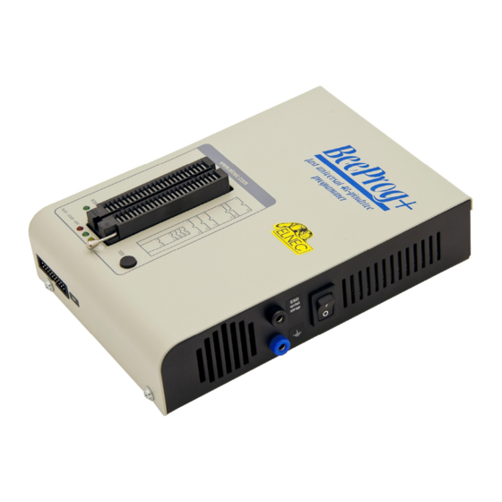
BeeProg+
Universal 48-pindrive Programmer with USB/LPT interface and ISP capability
SmartProg2
Universal 40-pindrive Programmer with USB interface and ISP capability
MEMprog2
Universal memory Programmer
SEEprog
Serial EEPROM Programmer
ELNEC s.r.o.
Presov, Slovakia
th
27
Juny 2012
1
Advertisement
Table of Contents
Troubleshooting

Related Manuals for Elnec BeeHive204


Summary of Contents for Elnec BeeHive204
- Page 1 ELNEC s. r. o. User manual for BeeHive204 Very fast universal 4x 48-pindrive concurrent multiprogramming system with ISP capability BeeProg2 Very fast universal 48-pindrive Programmer with USB/LPT interface and ISP capability BeeProg2C Very fast universal 48-pindrive Programmer with USB interface and ISP capability...
- Page 2 ELNEC s.r.o. The control program is copyright ELNEC s.r.o., Presov, Slovakia. The control program or any part of it may not be analyzed, disassembled or modified in any form, on any medium, for any purpose.
-
Page 3: How To Use This Manual
HELP within the control program rather than the printed User manual. Revisions are implemented in the context sensitive help before the printed User manual. Dear customer, thank you for purchasing one of the ELNEC programmer. _____________________________________ Please, download actual version of manual from ELNEC WEB site (www.elnec.com), if... -
Page 4: Table Of Contents
Detailed description ........................15 BeeHive204 ............................16 Introduction ...........................17 BeeHive204 elements ........................19 Manipulation with the programmed device ...................20 In-system serial programming by BeeHive204 ................20 Selftest and calibration check .......................22 Technical specification........................23 BeeProg2 / BeeProg2C / BeeProg+ ....................30 Introduction ...........................31 BeeProg2 / BeeProg2C / BeeProg+ elements................33 Connecting BeeProg2 / BeeProg2C / BeeProg+ to the PC ............34... - Page 5 ELNEC s. r. o. File..............................81 Buffer ............................87 Device............................95 Programmer..........................125 Options ............................130 Help ............................142 PG4UWMC ............................. 144 Common notes ..........................154 Maintenance ..........................155 Software ............................. 156 Hardware ............................ 162 ISP (In-System Programming)....................162 Other............................166 Troubleshooting and warranty ....................
- Page 6 ELNEC s. r. o. Conventions used in the manual References to the control program functions are in bold, e.g. Load, File, Device, etc. References to control keys are written in brackets <>, e.g. <F1>. Terminology used in the manual: Device...
-
Page 7: Introduction
Introduction Introduction... - Page 8 All programmers are driven by an easy-to-use, control program with pull-down menus, hot keys and online help. Control program is common for all the ELNEC programmers. Advanced design, including protection circuits, original brand components and careful manufacturing allows us to provide a three-years warranty for BeeHive204, BeeProg2,...
-
Page 9: Products Configuration
Introduction from Elnec company. The warranty conditions of Elnec sellers may differ depending on the target country law system or Elnec seller’s warranty policy. Note: We don’t recommend use programmers MEMprog2 and SEEprog for In-circuit programming. See FAQ on site www.elnec.com. -
Page 10: Pc Requirements
ELNEC s. r. o. PC requirements Minimal PC requirements OS - Windows 2000 2000 2000 2000 2000 C2D 2,6GHz RAM [MB] 1000 free disk space [MB] • • USB 2.0 high speed • • • USB 1.1 • • •... -
Page 11: Free Additional Services
We also offer the following new services in our customer support program: Keep-Current and AlgOR. • Keep-Current is a service by which ELNEC ships to you the latest version of the control program for programmer and the updated user documentation. A Keep-Current service is your hassle-free guarantee that you always have access to the latest software and documentation, at minimal cost. -
Page 12: Quick Start
ELNEC s. r. o. Quick Start... - Page 13 Double click on After start, control program PG4UW automatically scans all existing ports and searches for any connected ELNEC programmer. Program PG4UW is common for all ELNEC programmers hence PG4UW will try to find all supported programmers. Menu File is used for source files manipulation, settings and viewing directory, changes drives, changes start and finish address of buffer for loading and saving files and loading and saving projects.
- Page 14 ELNEC s. r. o. 4. check, if the device is blank: click on 5. program device: click on 6. additional verify of device: click on...
-
Page 15: Detailed Description
Detailed description Detailed description... -
Page 16: Beehive204
ELNEC s. r. o. BeeHive204... -
Page 17: Introduction
The operator merely removes the finished chip and inserts a new chip. Operator training is therefore minimized... BeeHive204 support all kinds of types and silicon technologies of today and tomorrow programmable devices without family-specific module. You can be sure the next devices support require the software update and (if necessary) simple package converter (programming adapter), therefore the ownership cost are minimized. - Page 18 The remote control feature allows PG4UW software to be flow controlled by other application – either using .BAT file commands or using DLL file. For BeeHive204 is remote control limited for ISP programming only. Please use BeeHive204AP for automated off line programming.
-
Page 19: Beehive204 Elements
It is important to remember that in most cases new devices require only a software update due to the BeeHive204 is truly universal programmer. With our prompt service you can have new devices can be added to the current list within hours! -
Page 20: Manipulation With The Programmed Device
ELNEC s. r. o. 11) type B USB connector for PC ↔ BeeHive204 communication cable Manipulation with the programmed device After selection of desired device for your work, you can insert it into the open ZIF socket (the lever is up) and close socket (the lever is down). The correct orientation of the programmed device in ZIF socket is shown on the picture near ZIF socket on the programmer's cover. - Page 21 BeeHive204 Front view at ISP connector. H/L/read driver pins 3, 5, 7, 9, 11, 13 of ISP connector pin 14 of ISP connector pin of ISP pin of ISP drivers in programmer drivers in programmer connector connector Float Read YES!
-
Page 22: Selftest And Calibration Check
• Use only attached ISP cable. When you use other ISP cable (other material, length…), programming may occur unreliable. • BeeHive204 can supply programmed device (pin 1 of ISP connector) and target system (pins 19 and 20 of ISP connector) with limitation (see Technical specification / ISP connector). -
Page 23: Technical Specification
Calibration test POD, Type I must be inserted as 48 pins device. • Run calibration test of programmer in PG4UW (Programmer / Calibration test). Technical specification Specification (BeeHive204 multiprogramming system) • 4x universal programming module (4x 48-pin DIL ZIF sockets) • operation result LEDs, LED power •... - Page 24 ELNEC s. r. o. • banana jack for ESD wrist straps connection • banana jack for connection to ground Specification (valid for each programming module) HARDWARE Base unit, DACs • USB 2.0 high-speed compatible port, up to 480 Mb/s transfer rate •...
- Page 25 BeeHive204 • Flash EPROM: 28Fxxx, 29Cxxx, 29Fxxx, 29BVxxx, 29LVxxx, 29Wxxx, 49Fxxx series, Samsung's K8Fxxxx, K8Cxxxx, K8Sxxxx, K8Pxxxx series, from 256Kbit to 1Gbit, with 8/16 bit data width, full support for LV series • NAND FLASH: Samsung K9xxx, Hynix HY27xxx, Toshiba TC58xxx, Micron MT29Fxxx, Spansion S30Mxxx, Numonyx (ex STM) NANDxxx •...
- Page 26 ELNEC s. r. o. • Microcontrollers MDT 1xxx and 2xxx series • Microcontrollers Microchip PICmicro: PIC10xxx, PIC12xxx, PIC16xxx, PIC17Cxxx, PIC18xxx, PIC24xxx, dsPIC, PIC32xxx series • Microcontrollers Motorola/Freescale: HC05, HC08, HC11, HC12, HCS08, RS08, S12, S12X, MC56F, MCF51, MCF52 series • Microcontrollers Myson MTV2xx, 3xx, 4xx, 5xx, CS89xx series •...
- Page 27 • FPGA: Actel: ProASIC3, IGLOO, Fusion • FPGA: Lattice: MachXO, LatticeXP, ispXPGA Notes: For all supported devices see actual Device list on www.elnec.com. Package support • support all devices in DIP with default socket • package support includes DIP, SDIP, PLCC, JLCC, SOIC, SOP, PSOP, SSOP, TSOP, TSOPII, TSSOP, QFP, PQFP, TQFP, VQFP, QFN (MLF), SON, BGA, EBGA, FBGA, VFBGA, UBGA, FTBGA, LAP, CSP, SCSP etc.
- Page 28 ELNEC s. r. o. • Algorithm updates: software updates are available regularly, approx. every 4 weeks, free of charge (Internet download). OnDemand version of software is available for highly needed chips support and/or bugs fixes. Available nearly daily. • Main features: revision history, session logging, on-line help, device and algorithm...
- Page 29 BeeHive204 • JAM (JEDEC STAPL Format), JBC (Jam STAPL Byte Code), STAPL (STAPL File) JEDEC standard JESD-71 • VME (ispVME file VME2.0/VME3.0) • SVF (Serial Vector Format revision E) • STP (Actel STAPL file) GENERAL • supply voltage AC 100-240V, max. 1.2A, 50-60Hz •...
-
Page 30: Beeprog2 / Beeprog2C / Beeprog
ELNEC s. r. o. BeeProg2 / BeeProg2C / BeeProg+... -
Page 31: Introduction
BeeProg2 / BeeProg2C / BeeProg+ Introduction BeeProg2 is a very fast universal USB/LPT interfaced universal programmer built to meet the strong demand of the small manufacturing and developer’s community for the fast and reliable universal programmer. BeeProg2C is a cost effective version of BeeProg2 programmer (without some special devices and LPT port interface). - Page 32 ELNEC s. r. o. down to 1.8V so you'll be ready to program the full range of today's advanced low-voltage devices. BeeProg2 / BeeProg2C / BeeProg+ performs device insertion test (wrong or backward position) and contact check (poor contact pin-to-socket) before it programs each device.
-
Page 33: Beeprog2 / Beeprog2C / Beeprog+ Elements
BeeProg2 / BeeProg2C / BeeProg+ Jam files of JEDEC standard JESD-71 are interpreted by Jam Player. Jam files are generated by design software which is provided by manufacturer of respective programmable device. Chips are programmed in ZIF or through ISP connector (IEEE 1149.1 Joint Test Action Group (JTAG) interface). -
Page 34: Connecting Beeprog2 / Beeprog2C / Beeprog+ To The Pc
ELNEC s. r. o. Power supply connector LPT connector for PC ↔ BeeProg2 / BeeProg+ communication cable. For BeeProg2C after upgrade to BeeProg2 10) USB connector for PC ↔ BeeProg2 / BeeProg2C / BeeProg+ communication cable Connecting BeeProg2 / BeeProg2C / BeeProg+ to... -
Page 35: Manipulation With The Programmed Device
BeeProg2 / BeeProg2C / BeeProg+ Using LPT port Switch off PC and programmer. Insert the communication cable included with your BeeProg2 / BeeProg+ programmer package to a free printer port on your PC. If your computer is equipped with only one printer port, substitute the programmer cable for the printer cable. Connect the opposite cable end to the programmer. -
Page 36: In-System Serial Programming By Beeprog2 / Beeprog2C / Beeprog
ELNEC s. r. o. programmer, but the content of actually programmed cell may remains undefined. Don't unplug the target device from the ZIF socket during work with device (LED BUSY shine). In-system serial programming by BeeProg2 / BeeProg2C / BeeProg+ For general definition, recommendation and direction about ISP see section Common notes / ISP please. - Page 37 (ISP) suffix after name of selected device. These specifications correspond with application notes published of device manufacturers. Used application notes you may find on www.elnec.com, section Support / Application Notes. Note: Pin no. 1 is signed by triangle scratch on ISP cable connectors.
-
Page 38: Multiprogramming By Beeprog2 / Beeprog2C / Beeprog
ELNEC s. r. o. Multiprogramming by BeeProg2 / BeeProg2C / BeeProg+ During installation of PG4UW at Select Additional Tasks window you check, if is allowed install BeeProg2 / BeeProg2C / BeeProg+ multiprogramming control support. For start of BeeProg2 / BeeProg2C / BeeProg+ multiprogramming is necessary run special control program pg4uwmc.exe. -
Page 39: Technical Specification
BeeProg2 / BeeProg2C / BeeProg+ Calibration test • Insert 48 Pins Calibration test POD, Type I into ZIF socket of the programmer. 48 Pins Calibration test POD, Type I must be inserted as 48 pins device. • Run calibration test of programmer in PG4UW (Programmer / Calibration test). Technical specification HARDWARE Base unit, DACs... - Page 40 ELNEC s. r. o. • 1x VCCP voltage (range 2V..7V/100mA) • programmed chip voltage (VCCP) with both source/sink capability and voltage sense • and 1x VPP voltage (range 2V..25V/50mA) • Target system power supply voltage (range 2V..6V/250mA) • ESD protection on each pin of ISP connector (IEC1000-4-2: 15kV air, 8kV contact) •...
- Page 41 BeeProg2 / BeeProg2C / BeeProg+ • Microcontrollers MCS51 series: 87Cxxx, 87LVxx, 89Cxxx, 89Sxxx, 89Fxxx, 89LVxxx, 89LSxxx, 89LPxxx, 89Exxx, 89Lxxx, all manufacturers, • Philips LPC series • Microcontrollers Intel 196 series: 87C196 KB/KC/KD/KT/KR/... • Microcontrollers Atmel ARM. ARM7: AT91SAM7Sxx, AT91SAM7Lxx, AT91SAM7Xxx, AT91SAM7XCxx, AT91SAM7SExx series;...
- Page 42 ELNEC s. r. o. • Microcontrollers 51 series: 87xx Programmer, through ISP connector • Serial E(E)PROM: IIC series, MW series, SPI series, KEELOQ series, PLD configuration memories, UNI/O series • 1-Wire E(E)PROM: DS1xxx, DS2xxx • Serial Flash: standard SPI (25xxx), DataFlash (AT45Dxxx, AT26Dxxx) •...
- Page 43 BeeProg2 / BeeProg2C / BeeProg+ • package support includes DIP, SDIP, PLCC, JLCC, SOIC, SOP, PSOP, SSOP, TSOP, TSOPII, TSSOP, QFP, PQFP, TQFP, VQFP, QFN (MLF), SON, BGA, EBGA, FBGA, VFBGA, UBGA, FTBGA, LAP, CSP, SCSP etc. • support devices in non-DIP packages up to 48 pins with universal adapters •...
- Page 44 ELNEC s. r. o. • interprete the VME files compressed binary variation of SVF files • security • insertion test, reverse insertion check • contact check • ID byte check • special • production mode (automatic start immediately after device insertion) •...
-
Page 45: Smartprog2
SmartProg2 SmartProg2... -
Page 46: Introduction
ELNEC s. r. o. Introduction SmartProg2 is next member of new generation of Windows based ELNEC universal programmers. Programmer is built to meet the demands of the development labs and field engineers to universal, but portable programmer. SmartProg2 is a small, fast and powerful programmer of all kinds of programmable devices. -
Page 47: Smartprog2 Elements
SmartProg2 The software also provides a lot of information about programmed device. As a special, the drawings of all available packages, explanation of chip labeling (the meaning of prefixes and suffixes at the chips) for each supported chip are provided. The software provide full information for ISP implementation: Description of ISP connector pins for currently selected chip, recommended target design around in-circuit programmed chip and other necessary information. -
Page 48: Connecting Smartprog2 To Pc
ELNEC s. r. o. USB connector for PC ↔ SmartProg2 communication cable Power supply connector Power supply connector Note: Due to low power consumption of SmartProg2 in inactive state, it doesn't require power switch. When the power LED indicator glows with a low intensity the SmartProg2 is in inactive mode. -
Page 49: In-System Serial Programming By Smartprog2
(ISP) suffix after name of selected device. These specifications correspond with application notes published of device manufacturers. Used application notes you may find on www.elnec.com, section Support / Application Notes. Note: Pin no. 1 is signed by triangle scratch on ISP cable connectors. -
Page 50: Selftest
ELNEC s. r. o. Note: H/L/read SmartProg2 driver H/L/read driver pin of ISP in programmer connector PU/PD driver in programmer C1=1nF, R1=1k3, R2=22k Selftest If you feel that your programmer does not react according to your expectation, please run the programmer selftest using Diagnostic POD, enclosed with the standard delivery package. - Page 51 SmartProg2 • FPGA based TTL driver provides H, L, CLK, pull-up, pull-down on all pindriver pins, level H selectable from 1.8 V up to 5V • continuity test: each pin is tested before every programming operation ISP connector • 10-pin male type with miss insertion lock •...
- Page 52 • (*2) - there exist only few adapters for devices with more than 40 pins. Therefore think please about more powerful programmer (BeeProg2 / BeeProg2C / BeeProg+), if you need to program devices with more than 40 pins • For all supported devices see actual Device list on www.elnec.com. I.C. Tester • Static RAM: 6116..624000...
- Page 53 SmartProg2 • statistic • count-down mode Buffer operations • view/edit, find/replace • fill, copy, move, byte swap, word/dword split • checksum (byte, word) • print File load/save • no download time because programmer is PC controlled • automatic file type identification Supported file formats •...
-
Page 54: Memprog2
ELNEC s. r. o. MEMprog2... -
Page 55: Introduction
MEMprog2 Introduction MEMprog2 is next member of new generation of Windows based ELNEC specialized programmers. Programmer is built to meet the demands of the development labs and field engineers for a specialized memory programmer. MEMprog2 can be upgraded to SmartProg2 using Xprog2 to SmartProg2 upgrade kit (ord.no.60-0048). -
Page 56: Memprog2 Elements
ELNEC s. r. o. The rich-featured autoincrement function enables to assign individual serial numbers to each programmed device - or simply increments a serial number, or the function enables to read serial numbers or any programmed device identification signatures from a file. -
Page 57: Connecting Memprog2 To Pc
MEMprog2 Power supply connector Connecting MEMprog2 to PC For MEMprog2 order of connecting USB cable and power supply to programmer is irrelevant. Problems related to the MEMprog2 PC interconnection, and their removing If you have any problems with MEMprog2 PC interconnection, see section Common notes please. -
Page 58: Technical Specification
ELNEC s. r. o. Technical specification HARDWARE Programmer • two D/A converters for VCCP and VPP, controllable rise and fall time • VCCP range 0..7V/350mA • VPP range 0..25V/200mA • USB 2.0/1.1 compatible interface • selftest capability ZIF socket, pindriver •... - Page 59 MEMprog2 • For all supported devices see actual Device list on www.elnec.com. I.C. Tester • Static RAM: 6116..624000 Programming speed Device Operation Mode Time 27C010 programming and verify in ZIF 24 sec AT29C040A programming and verify in ZIF 32 sec...
- Page 60 ELNEC s. r. o. Supported file formats • unformatted (raw) binary • HEX: Intel, Intel EXT, Motorola S-record, MOS, Exormax, Tektronix, ASCII-SPACE-HEX GENERAL • operating voltage 15..20V DC, max. 500mA • power consumption max. 6W active, 1.4W inactive • dimensions 160x97x35 mm (6.3x3.8x1.4 inch) •...
-
Page 61: Seeprog
SEEprog SEEprog... -
Page 62: Introduction
ELNEC s. r. o. Introduction SEEprog is universal programmer of all serial EEPROM in 8-pin DIL package. SEEprog programs EEPROM with interface IIC, SPI and Microwire, and also specialty as for example digital thermometers. The programmer supports LV (3.3V) devices too. -
Page 63: Seeprog Elements
SEEprog SEEprog elements 14 pin ZIF socket. Only 8 bottommost pins are active, as shown at the picture at the left. power LED LPT connector for PC ↔ SEEprog communication cable work result LED Power supply connector Power supply connector Connecting SEEprog programmer to PC Switch off the PC and programmer. -
Page 64: Manipulation With The Programmed Device
ELNEC s. r. o. • When connecting the programmer to the PC: FIRST insert the communications cable and THEN the power-supply connector. • When disconnecting the programmer from the PC: FIRST disconnect the power-supply connector and THEN the communication cable. - Page 65 SEEprog • For all supported devices see actual Device list on www.elnec.com. SOFTWARE • Algorithms: only manufacturer approved or certified algorithms are used. • Algorithm updates: software updates are available approx. every 4 weeks, free of charge. • Main features: revision history, session logging, on-line help, device and algorithm...
-
Page 66: Setup
ELNEC s. r. o. Setup... -
Page 67: Software Setup
The programmer package contains a CD with the control program, useful utilities and additional information. The permission to freely copy the content of the CD is granted in order to demonstrate how ELNEC programmers work. For programmers connected through USB (LPT) port, control program requires correctly... - Page 68 ELNEC s. r. o. Step 3. Click on “Next” button Step 4. For change default folder click on “Browse” button, select the destination folder. Then click on “Next” button...
- Page 69 Setup Step 5. For change default folder click on “Browse” button, select the destination folder. Then click on “Next” button Step 6. Check if “Install Multiprogramming control support” is selected. Change default setting, if you want. Then click on “Next” button...
- Page 70 ELNEC s. r. o. Step 7. Check your setting and then click on “Install” button Step 8. Installation process will start.
- Page 71 Setup Step 9. This window will be displayed for first time installation of current version of driver only. Click on “Continue Anyway” button. For Windows Vista: Click “Install this driver software anyway”...
- Page 72 ELNEC s. r. o. Step10. Click “Finish” button to finish setup. Step 11. For Windows Vista only: Click “This program installed correctly”...
-
Page 73: Hardware Setup
In order to exploit all the capabilities of programmer we recommend using the latest version of PG4UW. You may download the latest version of programmer software (file pg4uwarc.exe) from our Internet site www.elnec.com, part download. Copy pg4uwarc.exe to a temporary directory, disconnect programmer from PC and then launch it. - Page 74 ELNEC s. r. o. Step 5. Windows will start with “Found new hardware wizard”. For Windows XP, Service Pack 2 users only: Select “No, not this time” and then click on “Next” button. For all: Select “Install the software automatically” and then click on “Next” button.
- Page 75 Setup Step 6. Click on “Continue Anyway” button. For Windows Vista: Click “Install this driver software anyway”...
- Page 76 Click “Finish” button to finish setup. Step 8. “Found new hardware wizard” will launch for each programmer one time (for BeeHive204 4 times). Hardware setup will be continued with Step 5. Note: If a different USB port on the PC is used for the next connection of programmer,...
- Page 77 PG4UW PG4UW...
-
Page 78: Pg4Uw-The Programmer Software
ELNEC s. r. o. PG4UW-the programmer software Program PG4UW is common control program for all ELNEC programmers. We guarantee running of these programs under all of above mentioned operating systems without any problems. Also background operation under Windows is error-free. - Page 79 PG4UW Description of the user screen Windows program PG4UW Toolbars Under main menu are placed toolbars with button shortcuts of frequently used menu commands. Toolbars are optional and can be turned off by menu command Options / View. Log window Log window contains the flow-control progress information about almost every operation made in PG4UW.
- Page 80 ELNEC s. r. o. Panel Addresses Panel Addresses contains information about actual address ranges of currently selected device, loaded file and buffer start-end address settings. Some devices allow modifying default device and buffer address ranges by menu command Device / Device options / Operation options.
-
Page 81: File
PG4UW List of hot keys <F1> Help Calls Help <F2> Save Save file <F3> Load Load a file into the buffer <F4> Edit Viewing/editing of buffer <F5> Select/default Target-device selection from 10 last selected devices list <Alt+F5> Select/manual Target-device selection by typing device/vendor name <F6>... - Page 82 ELNEC s. r. o. ASCII SPACE format Very simple hex file format similar as ASCII HEX without checksum field, without start (STX) and end (ETX) characters. Each data byte is represented as 2 hexadecimal characters, and is separated by white space from all other data bytes. The address field is separated by white space from data bytes.
- Page 83 PG4UW significant value in the sequence) is stored first (at the lowest storage address). Little-endian is an order in which the "little end" (least significant value in the sequence) is stored first. For example, in a big-endian computer, the two bytes required for the hexadecimal number 4F52 would be stored as 4F52H in storage address 1000H as: 4FH is stored at storage address 1000H, and 52H will be at address 1001H.
- Page 84 ELNEC s. r. o. A data block started at address FFFF0H. It is a S2 format with length of address array of 3 bytes. For all data reading you can set Negative offset option and value of negative offset to FFFF0H.
- Page 85 PG4UW The standard dialog Load project contains additional window - Project description - placed at the bottom of dialog. This window is for displaying information about currently selected project file in dialog Load project. Project information consists of: • manufacturer and name of the first device selected in the project •...
- Page 86 ELNEC s. r. o. Upper half displays information about actual program configuration including currently selected device, program mode, date and time, etc., and is not writable. These actual program settings are used for creation of project description header. Bottom half is user editable and contains project description (arbitrary text) which usually consists of project author and some notes.
-
Page 87: Buffer
PG4UW 2. List of lastly used projects is displayed. Click the project you want to reload. File / Project options This option is used for display/edit project options of actually loaded project. Project options mean basic description of project including following project data: •... - Page 88 ELNEC s. r. o. Ctrl+F2 erase buffer with specified blank value Ctrl+Shift+F2 fill buffer with random data copy block is used to copy specified block of data in current buffer on new address. Target address needn't be out from source block addresses.
- Page 89 PG4UW which is able to work with large text files. In user defined text editor user can print or save to file selected block of buffer. The external editor path and name is saved automatically to disk. Find dialog box Enter the search string to Find to text input box and choose <Find>...
- Page 90 ELNEC s. r. o. Note: Characters 0 and 1 immediately changes content of edit area. Buffer / Fill block Selecting this command causes filling selected block of buffer by requested hex (or ASCII) string. Selecting option "Allow address history logging" activates saving of recently confirmed values.
- Page 91 PG4UW Swap bytes operation from Start address 0 to End address N modifies data in buffer by following tables: Swap 2-bytes Swap 4-bytes Swap Mirror bits Original Address inside 16-bit inside 32-bit nibbles inside Data words words inside bytes bytes 0000h 0001h 0002h...
- Page 92 ELNEC s. r. o. Note: Address history values are common for all buffer data manipulation dialogs. Default address range is set according to buffer range of selected device. Selecting option "Maintain last inserted values" causes that for the next time you open this dialog, previously confirmed values will be reloaded as default.
- Page 93 PG4UW problem to check the checksum of buffer, when data on some addresses are changed by serialization engine before programming of each device. If part of buffer used for serialization is excluded from checksum calculation, the checksum of buffer data will not be changed by serialization data changes.
- Page 94 ELNEC s. r. o. Note: If Word size was selected, a low byte of checksum value will be written on address specified in box Insert address and a high byte will be written on address incremented by one. Similarly it is for DWORD.
-
Page 95: Device
PG4UW Buffer data are summed word-by-word irrespective of current buffer view mode organization. Any carry bits exceeding 32-bits are neglected. This checksum mode is indicated by string (x16 BE) displayed after checksum value in main program window. Term Big Endian means, the buffer checksum is calculated from words read from buffer in Big Endian mode. - Page 96 ELNEC s. r. o. Use a <Del> key for delete of current device from list of default devices. There isn’t possible to empty this list, if you repeat this access. The last device stays in buffer and the <Del> key isn't accepted.
- Page 97 PG4UW Device can be select by double click on a line from list with desired manufacturer name and device number or by entering manufacturer name and/or device number in a search box (use a key <Space> as a separation character) and press <Enter> or click OK button. Press a key <Esc>...
- Page 98 ELNEC s. r. o. If you wish display additional information about the current device, use button Device info or an <Ctrl+F1> key. This command provides a size of device, organization, programming algorithm and a list of programmers (including auxiliary modules) that supported this device.
- Page 99 PG4UW group Addresses: device start address (default 0) device end address (default device size-1) buffer start address (default 0) Split (default none) This option allows setting special mode of buffer when programming or reading device. Using split options is particularly useful when using 8-bit data memory devices in 16-bit or 32-bit applications.
- Page 100 ELNEC s. r. o. Note 2: In some special cases, several microcontrollers don't provide ID, if copy protection feature in the chip is set, even if device ID check setting in control program is set to "Enable". group Command execution:...
- Page 101 PG4UW Supply voltage (in mV) - supply voltage in target system. Control program checks or sets (it depends on programmer type) entered supply voltage in target system before every action on device. Disable test supply voltage - disables measure and checking supply voltage of programmed device, set in Supply voltage edit box, before action with device.
- Page 102 ELNEC s. r. o. Actual serialization settings for actually selected device are saving to disk along with associated device by File / Exit and save command. When incremental mode is active following actual settings are saved to configuration file: address, size, serial value, incremental step and settings of modes ASCII / BIN, DEC / HEX, LS byte / MS Byte first.
- Page 103 PG4UW S / N size option defines the number of bytes of serial value which will be written to buffer. For Bin (binary) serialization modes values 1-8 are valid for S / N size and for ASCII serialization modes values 1-16 are valid for S / N size. Address Address option specifies the buffer address, where serial value has to be written.
- Page 104 ELNEC s. r. o. Split serial number The option allows dividing serial number into individual bytes and placing the bytes at each Nth address of buffer. This feature is particularly useful for SQTP serialization mode for Microchip PIC devices when the device serial number can be the part of program memory as group of RETLW or NOP instructions.
- Page 105 PG4UW Note: Serial quick turn programming (SQTP) is Microchip specified standard for serial programming of Microchip PIC microcontrollers. Microchip PIC devices allows you to program a unique serial number into each microcontroller. This number can be used as an entry code, password, or ID number.
- Page 106 ELNEC s. r. o. We can do this by following steps: A) write four RETLW instructions at address 40H to main buffer (this can be done by hand editing buffer or by loading file with proper content). The bottom 8 bits of each RETLW instruction are not important now, because serialization will write correct serial number bytes at bottom 8 bits of each RETLW instruction.
- Page 107 PG4UW The buffer content with NOPs at address 800h before starting device program should look for example as following: Address Data 0000800 00 00 00 00 00 00 00 00 xx xx xx xx xx xx xx xx xx – means any byte value B) Set the serialization options as following: S/N size: 3 bytes...
- Page 108 ELNEC s. r. o. Address Data 0000080 CD xx xx xx AB xx xx xx 34 xx xx xx 12 Word16 buffer organization: Address Data 0000040 xxCD xxxx xxAB xxxx xx34 xxxx xx12 xxxx Note: When you are not sure about effects of serialization options, there is possible to test the real serial number, which will be written to buffer.
- Page 109 PG4UW ; Comment meaning is: basic part Basic part defines buffer address and array of bytes to write to buffer. Basic part must be always defined after label in line. optional part Optional part defines the second array of bytes and buffer address to write to buffer. One optional part can be defined after basic part of data.
- Page 110 ELNEC s. r. o. • Be careful to set correct addresses. Address must be defined inside device start and device end address range. In case of address out of range, warning window appears and serialization is set to disabled (None).
- Page 111 PG4UW Labels are identifiers for each no-empty line of input file. They are used for addressing each line of file. The labels should be unique within the file. Addressing lines of file means, that the required start label entered by user defines line in input file from which serial values reading starts.
- Page 112 ELNEC s. r. o. program moves used serialization data files to user specified directory of used serialization files • option Delete used file program deletes used serialization data files Directory This option is available in playlist From-file serialization mode and selected option "Move used file to specified directory".
- Page 113 PG4UW Serialization generator Specifies the path and name for the executable file which will generate serialization data file. First serial number This option is required to specify the initial serial number that will be passed to custom generator serialization program. The number is entered and displayed in hexadecimal format. Last serial number This option specifies the maximum value of serial number allowed.
- Page 114 ELNEC s. r. o. Serialization .dat file format Serialization .dat file generated by serialization generator must meet following text format. Serialization .dat file consists of records and serial data section. Record is line, which begin with one of Txx prefixes as described bellow. Value of “xx”...
- Page 115 PG4UW maximum ending serial number. This record can be used when -E command line parameter is specified, it means no zero Last serial value in dialog Serialization is specified. T11:<message> Less important warning or message. The serialization will not be interrupted.
- Page 116 ELNEC s. r. o. Device / Device options / Statistics Statistics gives the information about actual count of device operations, which were proceeded on selected type device. If one device is corresponding to one device operation, e.g. programming, the number of device operations will be equal to number of programmed devices.
- Page 117 PG4UW Actual statistics values are displaying in main window of control program in Statistics panel. Statistics panel contains four statistics values – Success, Operational failure, Other failure, Total and two Count down information values Count down and Remains. Meaning of the values is: Success number of operations which where successfully completed Operational failure...
- Page 118 ELNEC s. r. o. The menu command Device / Device options / Operation options allows to set another working area as the standard. Device / Read This command allows to read all device or its part into the buffer. The read procedure can also read the content of the chip configuration (if it exists and is readable).
- Page 119 PG4UW Device / Test This command executes a test with device selected from list of supported devices (e.g. static RAM) on programmers, which support this test. Device / IC test This command activates a test section for ICs separated by type to any libraries (on distribution CD).
- Page 120 ELNEC s. r. o. "AN 100: In-System Programmability Guidelines", "AN 122: Using Jam STAPL for ISP & ICR via an Embedded Processor" and related application notes for details. Software tools: Altera: MAX+plus II, Quartus II, SVF2Jam utility (converts a serial vector file to a Jam file), LAT2Jam utility (converts an ispLSI3256A JEDEC file to a Jam file);...
- Page 121 PG4UW Action Select desired action for executing. Jam file of version 2 consists of actions. Action consists of calling of procedures which are executed. Jam file of version 1 does not know statements 'action' and 'procedure', therefore choice Action is not accessible. Program flow starts to run instructions according to boolean variables with prefix DO_something.
- Page 122 ELNEC s. r. o. Notes: statements are used to store information about the Jam file. The information stored in NOTE fields may include any type of documentation or attributes related to the particular Jam program. Source file contains a program in Jam language. Jam program consists of a sequence of statements.
- Page 123 PG4UW After successful loading the STAPLE file, select an intending operation action in Device operation options (Alt+O shortkey)/STAPL configuration..(STAPL configuration ...). For device programming select PROGRAM from action list. List of all the actions for the programming file with describe can be found in ACTEL FlashPro User’s Guide on <http://www.actel.com>.
- Page 124 ELNEC s. r. o. Q: Is it possible to program Actel device with two different STAPLE file in one program action in PG4UW? A: Yes, it is possible. PG4UW control program has built-in multi-project solution for mentioned situation. As an example can be programming data content (first STAPL file) together with security encryption key(second STAPL file).
-
Page 125: Programmer
PG4UW Programmer Menu Programmer includes commands used for work with programmers. Programmer / Find programmer This item selects a new type of programmer and communication parameters. This command contains following items: Programmer - sets a new type of programmer for find. If a Search all is selected, the control program finds all supported programmers. - Page 126 ELNEC s. r. o. operations are controlled directly by user otherwise control program is in special mode, when device operations are controlled automatically with co-operation with Handler. Dialog Handler contains following items: Selected Handler select wished Handler type. Search at port select a COM port, which will be scanned for a requested Handler.
- Page 127 PG4UW Pins of programmer's ZIF excluded from sensing contains list of pins that will be ignored from testing by Automatic YES!. The reason to ignore the pins is mostly - capacitors connected to these pins. Button Setting Automatic YES! parameters will run wizard that can detect permanently connected pins (pins with capacitors) and set these pins to list of pins excluded from sensing.
- Page 128 Diagnostic POD for ISP connectors #2 is used for testing 20 pins ISP connector of programmers. Diagnostic POD for ISP connector #2 is available as standard accessory for BeeHive208S, BeeHive204, BeeProg2, BeeProg2C and BeeProg+. The order number: 70- 0680. Schematics of Diagnostic POD for ISP connectors #2 (if you are in hurry):...
- Page 129 Programmer / Calibration test Command executes test of programmer's calibration values using 48 Pins Calibration test POD, Type I, which is optional accessories for BeeHive204, BeeProg2, BeeProg2C and BeeProg+. The order number: 70-0438. There are tested voltage levels of TTL drivers, VCCP, VPP1 and VPP2 voltages on each pin of ZIF socket.
-
Page 130: Options
ELNEC s. r. o. Options The Options menu contains commands that let you view and change various default settings. Options / General options General options dialog allows user to control and set variety of PG4UW program options. The options can be saved to PG4UW configuration file when closing PG4UW application, or anytime by command Options / Save options. - Page 131 PG4UW Project file default extension is used for setting project files-extension used as default extension in File / Load project and File / Save project dialogs. Buffer This page allows you to select Erase buffer before selecting of new device action. This can be useful for some kind of special devices, which require exact type of data at certain addresses, and the data are not part of data file loaded to buffer for this device.
- Page 132 ELNEC s. r. o. • option New save verify errors to file just from last verify action. Before first write of new verify action is file deleted and created as new one • option Append verify errors from all verify actions are cumulated into the same file.
- Page 133 PG4UW • option Use Log file text truncating when file size limit is reached - when checked, the Log file size limit is on. It means, that when Log file size reaches specified value, the part of text included in Log file will be truncated. When the option is unchecked, the size of Log file is unlimited, respectively is limited by free disk space only.
- Page 134 ELNEC s. r. o. job_report_<ordnum>_<prjname>.jrp where <ordnum> is decimal order of the file. If there exist any report files with the same name, then order for new report file is incremented about order of existing files. <prjname> is project file name of recently used project, and without the project file name extension.
- Page 135 PG4UW By LED Busy blinking - the programmer, regardless of the number of ZIF sockets of the programmer, indicates the state when a device is programmed and the programmer with software wait for inserting a new device mode by blinking with the LED Busy. After an operation with a device is done, one of the status LEDs (OK or Error) lights, in dependence on the result of previous operation and the LED Busy is blinking.
- Page 136 ELNEC s. r. o. Prompt for save program asks user for saving options before quitting program. User can select to save or not to save options Other Page Other allows user to manage other program settings. Panel Application priority allows user to set the priority of the program. Priority settings can affect performance of programmer (device programming time), especially if there are running more demanding applications in the system.
- Page 137 PG4UW insignificance. Protected mode is suitable for the programming of a large amount of the same type of devices. Protected mode function is available independently in single programming control software PG4UW and in multiprogramming control software PG4UWMC. Protected mode in PG4UW There are two ways how to switch program to Protected mode: 1.
- Page 138 ELNEC s. r. o. Protected mode in PG4UWMC Program PG4UWMC has Protected mode very similar to program PG4UW. The difference is, that Protected mode can be activated by menu command but cannot be activated by Project file. Another difference is, that Protected mode settings of PG4UWMC are saved to configuration .ini file of PG4UWMC while program PG4UWMC is closed.
- Page 139 PG4UW • Sub-project means classic project file which has been included into Multi-project file during Multi-project file build. • Project file - a special type of file, that combines buffer data, device operation options, special options and some level of safety features. It completely defines the way how to treat with the device.
- Page 140 ELNEC s. r. o. • Buttons of device operation Blank, Verify, Program, Erase, or Run are used for running of selected device operation on all chips (sub-devices) listed in table Sub-projects. • In "Multi operation" mode, one of all available operations can be run at a time (the same operation on each sub-device).
- Page 141 PG4UW Multichip_original_part_name [package_type] (part n) Example: Master-device: TV0057A002CAGD [FBGA107] Sub-devices #1 TV0057A002CAGD [FBGA107] (NAND) #2 TV0057A002CAGD [FBGA107] (NOR) Using of Multi-project for running of device operation Typical usage of existing Multi-project file has following order. For single programming in PG4UW: •...
-
Page 142: Help
ELNEC s. r. o. Notes: • serialization is not supported in multiprogramming mode (only single programming supports serialization) • count-down function is not supported now Options / Save options This command saves all settings that are currently supported for saving, even if auto-save is turned off. - Page 143 PG4UW Help / Device list (current programmer) This command makes a list of all devices supported by current programmer and saves it to ?????DEV.txt text file and ?????DEV.htm HTML file in the directory where control program is run from. Marks ????? are replaced by abbreviated name of current programmer, the device list is generated for.
-
Page 144: Pg4Uwmc
ELNEC s. r. o. PG4UWMC... - Page 145 PG4UWMC Program PG4UWMC is used for fully parallel concurrent device multiprogramming on more programmers or on one multiprogramming capable programmer connected to USB ports to the same computer. PG4UWMC is focused to the easy monitoring of high-volume production operations. Operator-friendly user interface of PG4UWMC combines many powerful functions with ease of use and provides overview of all important activities and operation results without burden of operator with non-important details.
- Page 146 ELNEC s. r. o. Main window of PG4UWMC consists of following parts: Menu and tool buttons Menu and tool buttons allow access to most of PG4UWMC functions. Tool button Settings Button is used to open PG4UWMC Settings dialog. Settings dialog is described bellow.
- Page 147 PG4UWMC Button is used to stop currently running device operations on all connected Programmer Sites. Button Help Button is used to display this help. Button Start remote control of beeHive204AP/BeeProg2AP The button is available for automated programmers only. It is used to start remote control of PG4UWMC interface.
- Page 148 ELNEC s. r. o. When there is requirement to program the same device types with the same data, the checkbox should be checked. • If the checkbox is checked, the project file for Site #1 will be used also for all other Programmer Sites.
- Page 149 PG4UWMC The Log file name specified by user is: "report.log". Then names of Log files will be: - PG4UWMC main Log file name - "report.log" - Site's #1 Log file name - "report_#1.log" - Site's #2 Log file name - "report_#2.log" - Site's #3 Log file name - "report_#3.log"...
- Page 150 ELNEC s. r. o. Common information: Index of Programmer Site is integer number from 1 to 8 which defines unambiguously each running Programmer Site. Serial number of Programmer Site defines unambiguously the programmer or programmer site used. Instance will search all programmers connected on USB Bus until it finds programmer (site) with desired serial number.
- Page 151 PG4UWMC When the checkbox Automatically save Job Report file is checked, the Job Report will be saved automatically to directory specified in edit field Job Report directory and with file name created as following: job_report_<ordnum>_<prjname>.jrp where <ordnum> is decimal order of the file. If there exist any report files with the same name, then order for new report file is incremented about order of existing files.
- Page 152 ELNEC s. r. o. Other Colors of the work result LEDs of programmer: • Standard LED color scheme (ERROR=red, BUSY=yellow) • Former LED color scheme (ERROR=yellow, BUSY=red) Note: These settings are available only for some types of programmers. If you can't see mentioned settings in menu, or menu is not enabled for editing, your programmer doesn't support LED color scheme customization.
- Page 153 PG4UWMC Command line parameters Program PG4UWMC supports following command line parameters: /prj:<file_name> Loads project file. Parameter <file_name> means full or relative project file path and name. There is also available to make Load project operation from command line by entering project file name without prefix /prj:...
-
Page 154: Common Notes
ELNEC s. r. o. Common notes... -
Page 155: Maintenance
Common notes Maintenance We recommend to follow the instructions and precautions herein to achieve high reliability of the programmer for a long period of time. The programmer maintenance depends on character and amount of its use. Regardless, the following recommendations are generally accepted: •... -
Page 156: Software
Software PG4UW is common control program for all of the ELNEC programmers. Thus, during work with him it is possible to find some items, those refer not to current selected programmer. Some special devices (e.g. Philips CoolRunner family) require external DAT files, that aren’t present in standard PG4UW SW delivery on CD. - Page 157 Common notes /Saveproject:<file_name> the command is used to save currently selected device type, buffer contents and configuration to project file. Command /Saveproject:... is equivalent to user selected command Save project in PG4UW control program. Please note, the file name Windows conventions must be fulfilled. It means also, that when file name contains spaces, the command line parameter must have the file name bounded inside quotation marks.
- Page 158 ELNEC s. r. o. Load project (/Prj:...) Load file (/Load file:...) EPROM/Flash select by ID Program device (/Program[:switch]) Close of control program (/Close only together with parameter /Program) Available command line parameters: /Axxx check programmer present on LPT port with address xxx only...
- Page 159 Common notes Examples: /Program /Program:noquest /Program:noanyquest /Close This parameter has sense together with /Program parameter only, and makes program PG4UW to close automatically after device programming is finished (no matter if operation was successful or not). /Saveproject:<file_name> The command is used to save currently selected device type, buffer contents and configuration to project file.
- Page 160 ELNEC s. r. o. The second block of data - 5 Bytes ABH CDH EFH 43H 21H are written to buffer at address FF0000H. The addressing looks like following: the first Byte at the lowest address Buffer Address Data FF0000H...
- Page 161 Common notes be in basic state, i.e. main program window focused, no modal dialogs displayed, no menu commands opened or executed 6. order of processing command line parameters when using more parameters together is defined firmly as following: step1 Load file (/Loadfile:...) step2 Load project (/Prj:...) step3 EPROM/FLASH autoselect step4 Program device (/Program[:switch])
-
Page 162: Hardware
Because BeeHive204, BeeProg2, BeeProg2C and BeeProg+ have internal power supply, follow these special precautions: • Circuit breakers (overcurrent protection) must be a part of building electrical installation. - Page 163 Target system mustn’t affect these signals during In-system programming. For in-system programmable devices manufacturers publish application notes. Design of ELNEC programmers together with respect of these application notes allows proper In- system programming. Condition is exactly respecting these application notes. Applications...
- Page 164 ELNEC s. r. o. notes, which ELNEC use in ISP programmers, are published in www.elnec.com, section Support / Application Notes. Please, read some notes for following recommended circuits. • Purpose of D1 diode is to protect the target circuit against a higher voltage, which is provided by ISP programmer.
- Page 165 Marginal verify is used after programming. Programmer must verify the program memory ® contents at both minimal and maximal power supply, therefore VDD pin of PICmicro must be isolated from rest of target system during programming. ELNEC recommended circuit for PICmicro:...
-
Page 166: Other
Note: External reset circuit is necessary only if VDD power-up slope is too slow. Other There is needful for regular running of control program for any ELNEC programmer that printer port, on which is programmer connected, must be reserved for this programmer only. - Page 167 Common notes 2. click with right mouse button to "My computer" item and select menu "Properties 3. in the "System properties" dialog select "Hardware" page and click to "Device manager" button 4. in the "Device manager" dialog select "Ports (Com & LPT)" (double click), it will show the list of all present LPT and COM ports There should be displayed at least one present LPT port.
-
Page 168: Troubleshooting And Warranty
ELNEC s. r. o. Troubleshooting and warranty... -
Page 169: Troubleshooting
Send the completed form by mail or fax to ELNEC (fax number in the control program, menu Help / About) or to your local dealer. If you send the form by fax please use black ink, a good pen and large letters! •... -
Page 170: If You Have An Unsupported Target Device
This warranty is limited to 25,000-cycles on DIL ZIF socket or 10,000-cycles on other ZIF sockets). If the product is diagnosed as defective, ELNEC s.r.o. or the authorized repair center will repair or replace defective parts at no charge. Parts used for replacement and/or whole programmer are warranted only for the reminder of the original warranty period. - Page 171 Troubleshooting and warranty ELNEC has used its best efforts to develop hardware and software that is stable and reliable. ELNEC does not guarantee that the hardware and software are free of "bugs", errors or defects. ELNEC's liability is always limited to contract's net value paid by a buyer.
Need help?
Do you have a question about the BeeHive204 and is the answer not in the manual?
Questions and answers