Table of Contents
Advertisement
Quick Links
Advertisement
Table of Contents
Troubleshooting

Related Manuals for Elnec BeeHive304


Summary of Contents for Elnec BeeHive304
- Page 1 User manual for BeeHive304 Ultra speed universal 4x 64-pindrive production multiprogrammer, design focused high-capacity memories programming. BeeProg3 Ultra speed universal 64-pindrive programmer, design focused on high-capacity memories programming.
- Page 2 Please consult manual on www.elnec.com. Elnec s.r.o. assumes no responsibility for misuse of this manual. Elnec s.r.o. reserves the right to make changes or improvements to the product described in this manual at any time without notice. This manual contains names of companies, software products, etc., which may be trademarks of their respective owners.
-
Page 3: How To Use This Manual
HELP within the control program rather than the printed User manual. Revisions are implemented in the context sensitive help before the printed User manual. Dear customer, thank you for purchasing one of the Elnec programmer. _____________________________________ Please, download actual version of manual from Elnec WEB site (www.elnec.com),... -
Page 4: Table Of Contents
Software ..............................9 Free additional services:........................9 Quick Start............................10 Detailed description ..........................13 BeeHive304............................14 Introduction ............................15 BeeHive304 elements........................19 Connecting BeeHive304 to the PC ....................21 Manipulation with the programmed device ..................21 Selftest and calibration check......................21 Technical specification........................23 BeeProg3 ..............................29 Introduction ............................30 BeeProg3 elements ..........................33 Connecting BeeProg3 to the PC ......................34... - Page 5 Elnec s. r. o. Conventions used in the manual References to the control program functions are in bold, e.g. Load, File, Device, etc. References to control keys are written in brackets <>, e.g. <F1>. Terminology used in the manual: Device...
-
Page 6: Introduction
Elnec s. r. o. Introduction... -
Page 7: Products Configuration
Introduction This user manual covers Elnec programmers BeeHive304 and BeeProg3. BeeHive304 is a desktop programmer but may be used as the core for automated programmers and automatic test equipments (ATE) too. It is ultra speed universal 4x64-pindrive concurrent multiprogramming system designed for high volume production programming of high capacity memories. - Page 8 "Hardware setup" chapter. Warning: It is not allowed to connect BeeHive304 or BeeProg3 programmer directly to PC via LAN cable. BeeHive304 or BeeProg3 may be connected via LAN cable using switch or router only. Free disk space requirement depends also on used IC device size and number of attached programming sites.
-
Page 9: Software
We also offer the following new services in our customer support program: Keep-Current is a service by which Elnec ships to you the latest version of the control program for programmer and the updated user documentation. A Keep-Current service is your hassle-free guarantee that you always have access to the latest software and documentation, at minimal cost. -
Page 10: Quick Start
Elnec s. r. o. Quick Start... - Page 11 Double click on After start, control program PG4UW automatically scans all existing ports and searches for any connected Elnec programmer. Program PG4UW is common for all Elnec programmers hence PG4UW will try to find all supported programmers. Menu File is used for source files manipulation, settings and viewing directory, changes drives, changes start and finish address of buffer for loading and saving files and loading and saving projects.
- Page 12 Elnec s. r. o. Programming a device 1. select device: click on 2. load data into buffer: from file: click on from device: insert device to AP3 programming module ZIF and click on 3. insert target device to AP3 programming module ZIF 4.
-
Page 13: Detailed Description
Detailed description Detailed description... -
Page 14: Beehive304
Elnec s. r. o. BeeHive304... -
Page 15: Introduction
For example, the 2 GB eMMC NAND Flash could be done in less than 100 sec - if programmed memory allow that speed. Tests show, that BeeHive304 is currently faster than all competitors in this price category, and for many chips it is the fastest at all. - Page 16 (pindriver signals and also supporting signals), connection to PC and power supply input, are protected against ESD up to 15kV. For the proper and reliable programming of ultra-fast memories the BeeHive304 utilizes specialized modules, optimally designed for specific device families, exactly according to the needs of programmed devices.
- Page 17 BeeHive304 programmers are enough to perform all jobs, then it is enough to use one control PC for whole programming system, for both machine control and also programmer software.
- Page 18 Graphic user interface provide overview of all important activities result without burden of operator with non-important details. There is used a project file to control the BeeHive304 multiprogramming system. Project file contains user data, chip programming setup information, chip configuration data, auto programming command sequence, etc.
-
Page 19: Beehive304 Elements
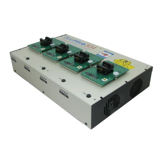
BeeHive304 elements Programming Module Interface (PMI) connectors work result LEDs of site power/sleep LED of site 6 x 4,2mm holes for fastening BeeHive304 to bottom or top plate programming module fixating screws button START temperature controlled cooling fans Front and top view to BeeHive304... - Page 20 13) LAN cable connected to programmer from rear side 14) rear side cable tie mounts for fixating power, USB and LAN cables Rear and top view to BeeHive304 15) power connector, 15V 6A 16) type B USB connector for PC...
-
Page 21: Connecting Beehive304 To The Pc
BeeHive304 Connecting BeeHive304 to the PC Using USB port Recommendation for connecting programmer to PC: 1. make ground connection between programmer and PC or other ground 2. connect programmer with PC via USB cable 3. connect power supply to programmer... - Page 22 Elnec s. r. o. Selftest of programmer site Put together Board A with Board B of AP3 diagnostic POD Insert AP3 diagnostic POD into Programming Module Interface (PMI) connectors of the programmer site. Run selftest of programmer in PG4UW (menu Programmer / Selftest).
-
Page 23: Technical Specification
Elnec only the programmers up to s/n 3004-00041(including) were supplied with 32GB SSD as... - Page 24 Elnec s. r. o. DEVICE SUPPORT Programmer, using programming modules: NAND FLASH: Samsung K9xxx, KFxxx, SK Hynix (ex Hynix) HY27xxx, H27xxx, Toshiba TC58xxx, TH58xxx, Micron MT29Fxxx, (ex Numonyx ex STM) NANDxxx, Spansion S30Mxxx, S34xxx, 3D-Plus 3DFNxxx, ATO Solution AFNDxxx, Fidelix FMNDxxx, Eon Silicon Sol.
- Page 25 BeeHive304 Special chips: Atmel Tire Pressure Monitoring ATA6285N, ATA6286N; PWM controllers: Zilker Labs, Analog Devices; Multi-Phase ICs: IR(Chil Semiconductor); Gamma buffers: AUO, Maxim, TI, ... Microcontrollers MCS51 series: 87Cxxx, 87LVxx, 89Cxxx, 89Sxxx, 89Fxxx, 89LVxxx, 89LSxxx, 89LPxxx, 89Exxx, 89Lxxx, all manufacturers, Philips LPC series...
- Page 26 All devices mentioned below, including both NAND Flash, are programmed at their maximal speed, the programming time can not be shorter. We're sorry, but there exist not very much devices, where the 20+MB/s BeeHive304 programming speed can be utilized Device...
- Page 27 BeeHive304 Conditions: Core2 Duo, 3.16 GHz, 1G RAM, USB 2.0 HS, Windows 7. Version of SW: 3.09, 10/2014. *1 Verification of programming is done by internal controller of eMMC device. The device receives a block of data plus CRC, if it all matches, the internal controller confirm the proper programming.
- Page 28 47-63Hz. Output voltage: 15V, 6A, output cable length 1200mm (47.2 inch) power consumption max. 90W active dimensions of BeeHive304 programmer: 320,5 x 205 x 58,4 mm (12,6 x 8,1 x 2,3 inch). Dimensions were measured without programming module inserted and does not include projections.
-
Page 29: Beeprog3
BeeProg3 BeeProg3... -
Page 30: Introduction
Elnec s. r. o. Introduction BeeProg3 is next member of Elnec universal programmer series, built to meet the strong appeal for an extremely fast and reliable programmer for high-capacity memories. BeeProg3 is designed with great emphasis on technical perfection and speed of hardware,... - Page 31 BeeProg3 Programmer pindrivers operate down to 0.8V, therefore the programmer is ready to program the full range of today's and tomorrow's advanced very-low-voltage devices. Extremely fast programming, achieved by using FPGA based state machine, fast processor and SSD, allow execution of all time-critical routines and data transfers inside of the programmer.
- Page 32 Elnec provides free shipping of programmer repaired under warranty back to customers worldwide. The warranty is valid from the date of purchase.
-
Page 33: Beeprog3 Elements
BeeProg3 BeeProg3 elements Programming Module Interface (PMI) connectors work result LEDs power/sleep LED of site button START programming module fixating screw “GND” banana jack can be used for grounding of the programmer “ESD wrist strap” banana jack is place for attaching of ESD wrist strap power switch temperature controlled cooling fan Right top view to BeeProg3... -
Page 34: Connecting Beeprog3 To The Pc
Elnec s. r. o. power supply connector 10) type B USB connector for PC BeeProg3 communication cable 11) LAN connector for network BeeProg3 communication cable Rear view to BeeProg3 Connecting BeeProg3 to the PC Using USB port Recommendation for connecting programmer to PC: 1. -
Page 35: Multiprogramming By Beeprog3
BeeProg3 Note: Programmer need not to be switched off and also the software may be running when: Inserting / removing AP3 programming module to / from Programming Module Interface (PMI) connectors Inserting / removing the target device to / from the AP3 programming module ZIF socket but none operation with target device can be active (LED BUSY light off). -
Page 36: Technical Specification
Elnec s. r. o. Calibration test Disconnect Board A from Board B of AP3 diagnostic POD Insert Board A of AP3 diagnostic POD into Programming Module Interface (PMI) connectors of the programmer. Run calibration test of programmer in PG4UW (menu Programmer / Calibration test). - Page 37 Elnec only the programmers up to s/n 1200-00053 (including) were supplied with 32GB SSD as...
- Page 38 Elnec s. r. o. MRAM: Everspin MRxxxxx8x, 3D Plus 3DMRxxxxxxxx NV RAM: Dallas DSxxx, SGS/Inmos MKxxx, SIMTEK STKxxx, XICOR 2xxx, ZMD U63x series Serial E(E)PROM: Serial E(E)PROM: 11LCxxx, 24Cxxx, 24Fxxx, 25Cxxx, 30TSExxx, 34Cxxx, 34TSxx, 59Cxxx, 85xxx, 93Cxxx, NVM3060, MDAxxx series, full support for LV...
- Page 39 Holtek, Novatek, Macronix, Princeton, Winbond, Samsung, Toshiba, Mitsubishi, Realtek, M- Square, ASP, Coreriver, Gencore, EXODUS Microelectronic, Topro, TinyARM, VersaChips, SunplusIT, M-Square, QIXIN, Signetic, Tekmos, Weltrend, Amic, Cyrod Technologies, Ember, Ramtron, Nordic Semiconductor, Samsung, ABOV Semiconductor... Notes: For all supported devices see actual Device list on www.elnec.com...
- Page 40 Elnec s. r. o. Package support package support includes DIP, SDIP, PLCC, JLCC, SOIC, SOP, PSOP, SSOP, TSOP, TSOPII, TSSOP, QFP, PQFP, TQFP, VQFP, QFN (MLF), SON, BGA, EBGA, FBGA, VFBGA, UBGA, FTBGA, LAP, CSP, SCSP, LQFP, MQFP, HVQFN, QLP, QIP etc..
- Page 41 BeeProg3 blank check, read, verify program erase configuration and security bit program checksum interpret the Jam Standard Test and Programming Language (STAPL), JEDEC standard JESD-71 interpret the VME files compressed binary variation of SVF files interpret the SVF files (Serial Vector Format) interpret the Actel STAPL Player files security insertion test...
- Page 42 Elnec s. r. o. dimensions of BeeProg3 programmer: 139,5 x 189,5 x 48,4 mm (5,5 x 7,5 x 1,9 inch). Dimensions were measured without programming module inserted and does not include projections. Total height of BeeProg3 programmer with programming module inserted depends on ZIF socket height and can vary between 66-78mm.
-
Page 43: Setup
Setup Setup... -
Page 44: Software Setup
The programmer package contains a CD with the control program, useful utilities and additional information. The permission to freely copy the content of the CD is granted in order to demonstrate how Elnec programmers work. For programmers connected through USB port, control program requires correctly installed... - Page 45 Setup Step 3. Click on “Next” button Step 4. For default setting you click on “Next” button. Setup will be continuing with Step 6. For change default setting you click on “Custom” and then on “Next” button.
- Page 46 Elnec s. r. o. Step 5. To change default folder click on “Browse” button, select the destination folder. Then click on “Next” button Step 6. To change default folder click on “Browse” button, select the destination folder. Then click on...
- Page 47 Setup Step 7. Check if “Install Multiprogramming control support” is selected. Change default setting, if you want. Then click on “Next” button Step 8. Check your settings and then click on “Install” button...
- Page 48 Elnec s. r. o. Step 9. Installation process will start. Step 10. Click “Finish” button to finish setup.
-
Page 49: Hardware Setup
In order to take advantage of all the capabilities of programmer we recommend using the latest version of PG4UW. You may download the latest version of programmer software from our Internet site www.elnec.com. Copy the software distribution file to a temporary directory, disconnect programmer from PC and then launch it. - Page 50 Elnec s. r. o. For Windows 7 and Windows 8. Step 5. In the notification area at task bar (mainly at lower right corner) you will see following notification bubble: After successfully installed driver for programmer you will see Note: if another programmer will be connected to PC (maybe to the same USB port) “Installing device driver software”...
- Page 51 Setup Step 6. Select “Install the software automatically” and then click on “Next” button. Step 7. Wizard will search for the programmer and start installation of driver automatically.
- Page 52 Step 9. “Found new hardware wizard” will launch for each programmer (programmer site) one time (for BeeHive304 - 4 times). Setup will continue with Step 5. Note: In Windows XP if a different USB port on the PC is used for next connection of the...
- Page 53 ZIF socket height. Total height can be determined by 66,5mm + ZIF socket height. Right top view to BeeHive304 with dimensions Minimal distance between BeeHive304 and other object is 2cm. It is necessary for good cooling of BeeHive304 and air ventilation around it.
- Page 54 Elnec s. r. o. BeeHive304 can be mounted on base plate by 6 screws M4 with nuts. Length of screw depends on base plate thickness. On base plate can be ø 4,5mm holes replaced with M4 internal threads. In this case you may use six M4x70 screws which are at standard delivery.
- Page 55 Setup BeeHive304 can be mounted below base plate 6 screws M4 with nuts. Length of screw depends on base plate thickness. On base plate can be ø 4,5mm holes replaced with M4 internal threads. In this case you may use six M4x70 screws which are at standard delivery.
- Page 56 ZIF socket height. Total height can be determined by 56,5mm + ZIF socket height. Right top view to BeeProg3 with dimensions Minimal distance between BeeHive304 and other object is 2cm. It is necessary for good cooling of BeeHive304 and air ventilation around it.
- Page 57 Setup BeeProg3 can be mounted on base plate by 3 screws M3. Length of screw depends on base plate thickness. Attention: For proper mounting of programmer on base plate, mounting screws must be minimal 3mm depth in programmer. To avoid damage of PCB in programmer mounting screws must be maximum 8mm depth in programmer.
-
Page 58: Pg4Uw Software
Elnec s. r. o. PG4UW software... -
Page 59: Pg4Uw The Programmer Software
PG4UW software PG4UW the programmer software Program PG4UW is common control program for all Elnec programmers. We guarantee running of these programs under all of above mentioned operating systems without any issues. Background operation under Windows is error-free. Using the programmer software... - Page 60 Elnec s. r. o. programming/verifying operation is running inside programmer. Buffer synchronization is indicated in PG4UW control program by message "Synchronizing buffers with programmer...". Progress of the data transfer is showed in separate window. Transfer can be canceled by pressing key <Esc> or pressing the window's exit button.
- Page 61 PG4UW software Log window Log window contains the flow-control progress information about almost every operation made in PG4UW. Operation can be: starting of PG4UW programmer search file/project load/save selection of device device operations (device read, blank check, programming, ...) remote control application connection and disconnection and other Content of Log window can be saved to file concurrently while information is written to Log window.
-
Page 62: File
Elnec s. r. o. reference to detailed Device info dialog, available also by menu Device / Device info reference to Advanced device options - this is available for some types of devices only Panel Statistics It contains statistics information about currently selected device. - Page 63 PG4UW software File formats description: ASCII HEX format Each data byte is represented as 2 hexadecimal characters, and is separated by white space from all other data bytes. The address for data bytes is set by using a sequence of $Annnn, characters, where nnnn is the 4-hex characters of the address.
- Page 64 Elnec s. r. o. format. Default set is from Options / General options in panel Load file format at tab File options. Note: Program is not able to recognize files in ASCII Hex format automatically, it recognizes them as binary. So download files in ASCII Hex format with disabled option for automatic file format recognition.
- Page 65 PG4UW software Negative offset and Automatic negative offset - set by two ways: manual or automatic. For manual set use option Negative offset and put wished offset value to its edit box. For automatic offset detection use option Automatic negative offset. This value is subtracted from current address for save data to buffer.
- Page 66 Elnec s. r. o. #xx5 - bad length of current line #xx6 - too big negative offset #xx7 - address is out of buffer range #xx8 - bad type of selected file format #xx9 - the file wasn't loaded all...
- Page 67 PG4UW software Example: Project file name: my_work.prj Control program's directory: c:\Program Files\Programmer\ The additional serialization file will be: c:\Program Files\Programmer\serialization\my_work.prj.sn Additional serialization file is created and refreshed after successful device program operation. The only requirement for creating additional serialization file is load project with serialization turned on.
- Page 68 Elnec s. r. o. Checkbox Set Protected mode of software after loading of this project file is used to save project in special mode called Protected mode. After clicking the button with key, password dialog appears, which is used to specify Protected mode password for project being saved, and another security options (disable other project loading, device operations restriction) to prevent operator's mistakes.
-
Page 69: Buffer
PG4UW software 1. From the File menu, choose Reload project. 2. List of lastly used projects is displayed. Click the project you want to reload. File / Project options This option is used for display/edit project options of actually loaded project. Project options mean basic description of project including following project data: device name and manufacturer project creation date... - Page 70 Elnec s. r. o. View/Edit Buffer This dialog is used to view (view mode) or edit (edit mode) data in buffer. Use arrow keys for select data for edit. The data in buffer outside of area where are located data for the selected chip are shown using gray background.
- Page 71 PG4UW software Note: characters 20H - FFH (mode ASCII) and numbers 0...9, A...F (mode HEX) immediately changes content of edit area. Warning: Editing of ASCII characters for word devices is disabled. Print buffer This command allows write selected part of buffer to printer or to file. Program uses at it an external text editor in which selected block of buffer is displayed and can be printed or saved to file, too.
- Page 72 Elnec s. r. o. Press <Esc> or click Cancel button to close dialog window. By pressing Replace button the dialog box is closed and a Question window is displayed. This window contains following choices: replaces found item and finds next...
- Page 73 PG4UW software Selecting option "Allow address history logging" activates saving of recently confirmed values. These are saved for each device separately, count is limited to last 15 items. Note: Address history values are common for all buffer data manipulation dialogs. Default address range is set according to buffer range of selected device.
- Page 74 Elnec s. r. o. Selecting option "Allow address history logging" activates saving of recently confirmed values. These are saved for each device separately, count is limited to last 15 items. Note: Address history values are common for all buffer data manipulation dialogs.
- Page 75 PG4UW software Tab Main checksum options contains options for Automatic checksum calculator with Main checksum value displayed in main window of PG4UW in table Addresses and in Log window of PG4UW (*2) Checksum calculator contains on-demand checksum calculator. (*1) Fields From address and To address are used to enter address range for main checksum calculation.
- Page 76 Elnec s. r. o. Tab Main checksum options allow you to set mode of Automatic checksum calculator. (*2) group Custom address range for main checksum Enabled - user defined addresses are used to calculate checksum of buffer data, otherwise, if Disabled, global Buffer start and Buffer end address is used for...
-
Page 77: Device
PG4UW software Buffer data are summed by bytes to sum by bytes to WORD using standard CRC-16 algorithm with polynomial x^16+x^15+x^2+1 (0x8005), init value 0, and XOR out 0 CRC-32 Buffer data are summed by bytes to DWORD using standard CRC-32 algorithm with polynomial 0x04C11DB7, init value 0xFFFFFFFF, and XOR out 0xFFFFFFFF an MD5 hash expressed as a sequence of 32 hexadecimal digits (128 bits) SHA-1... - Page 78 Elnec s. r. o. Note 1: The names of the programmable devices in software don't contain all characters, shown at the top of the chip or mentioned in the datasheet section part numbering. The names contain all characters necessary to identification of the device, but don't contain such codes, that have none influence to the programming, for example temperature code, speed code, packing type code, etc..
- Page 79 PG4UW software Select device ... / Only selected type This window allows selecting the desired type of the device. At the first - you must select a device type (e.g. EPROM) and device subtype (e.g. 64Kx8 (27512)), using mouse or cursor keys.
- Page 80 Elnec s. r. o. If more devices with identical chip ID and manufacturer's ID were detected, the list of these devices will be displayed. A corresponding device can be chosen from this list by selecting its number (or manufacturer name) from list and press <Enter> (or click OK button). Press a key <Esc>...
- Page 81 PG4UW software Even Device [ADDR] Buffer [2*ADDR] Device [ADDR] Buffer [1+ (2*ADDR)] 1./4 Device [ADDR] Buffer [4*ADDR] 2./4 Device [ADDR] Buffer [1+(4*ADDR)] 3./4 Device [ADDR] Buffer [2+(4*ADDR)] 4./4 Device [ADDR] Buffer [3+(4*ADDR)] Real addressing will be following: (all addresses are hexadecimal) Split type Device addresses Buffer addresses...
- Page 82 Elnec s. r. o. group Programming parameters This group is available for some types of devices. It contains settings of which device parts or areas have to be programmed. group Erase parameters This group is available for some types of devices. It contains special settings of erase modes of selected device.
- Page 83 PG4UW software Serialization. If Buffer settings box is not visible, the current serialization mode does not support extended buffers. Device / Device options / Serialization / Incremental mode & SQTP The Incremental mode & SQTP enables to assign individual serial numbers to each programmed device.
- Page 84 Elnec s. r. o. The special case is Binary Dec, which means BCD number style. BCD means the decimal number is stored in hexadecimal number, i.e. each nibble must have value from 0 to 9. Values A to F are not allowed as nibbles of BCD numbers.
- Page 85 PG4UW software 007FFF0 xx xx xx xx xx xx xx xx xx xx xx xx 01 00 00 16 The 3rd device Address Data 007FFF0 xx xx xx xx xx xx xx xx xx xx xx xx 02 00 00 16 etc.
- Page 86 Elnec s. r. o. Address Data 0000080 CD AB 34 12 xx xx xx xx xx xx xx xx xx xx xx xx Note: address 80H is because buffer has byte organization and PIC has word organization so it has equivalent program memory address 40H. When buffer has word organization x16,...
- Page 87 PG4UW software Example 2.b Use of serialization split with NOP instructions for Microchip PIC24FJ256 devices Device PIC24FJ256 has 24 bit wide instruction word. Instruction NOP has code 00xxxxh. Let's assume we want to use serialization in the same manner as SQTP serialization specified in Microchip MPLAB®: We can do this by following steps: A) Write NOP instructions (00xxxxh) at address 800h to main buffer of PG4UW.
- Page 88 Elnec s. r. o. When Split gap is set to 2 bytes, the buffer content will look as following: Byte buffer organization: Address Data 0000080 CD xx xx AB xx xx 34 xx xx 12 xx xx xx xx xx xx...
- Page 89 PG4UW software File format Classic From-file serialization input file has text format. The file includes addresses and arrays of bytes defining buffer addresses and data to write to buffer. Input file has text type format, which structure is: [label1] addr byte0 byte1 .. byten [labeln] addr byte0 byte1 ..
- Page 90 Elnec s. r. o. ‘;’ - the semicolon character means the beginning of a comment. All characters from „;„ to the end of line are ignored. Comment can be on individual line or in the end of definition line. Note: Label names can contain all characters except ‘[‘...
- Page 91 PG4UW software File format From-file serialization playlist file includes list of filenames which contain serialization data. The file format is similar to classic serialization file format. Following file format differences are for playlist files: 1. the playlist file must have special header at the first no empty line of file. The header is text line in format FILETYPE=PG4UW SERIALIZATION PLAYLIST FILE 2.
- Page 92 Elnec s. r. o. 6. click the OK button to accept the new serialization settings 7. run "Program" device operation You can see at the serialization indicating labels in the main window of PG4UW and also in info progress window during device programming and repeating of programming.
- Page 93 PG4UW software In dialog Serialization select in Mode panel option Custom generator mode. The following options will be displayed: Serialization data file Specifies the path and name for the data file that will contain the current serial number. When device is to be programmed, the PG4UW software calls user made serial number generator that updates the data file.
- Page 94 Elnec s. r. o. made by user. The path and name of the serialization program must be specified in the Serialization options dialog in Custom generator mode options. The program will be called from PG4UW every time the new serial data have to be generated.
- Page 95 PG4UW software The file consists of following information: line T01 - current serial number 000005h line T02 - ending (last) serial number 001006h line T03 - serialization data format after line T04 is Intel Hex line T04 - serialization data, which will be loaded to buffer of PG4UW before programming device, data are represented in Intel Hex format Optional records are: T05:<message>...
- Page 96 Elnec s. r. o. goto step 2. continue at step 8. 8. End of programming batch Notes: In case of error programming result, recent serial number is used, but generator will be called at step 3. anyway, even if the same number is used as for previously programmed device.
- Page 97 PG4UW software Adapter test failure number of operations which where not successfully completed due to incorrect programming adapter Insertion test failure number of operations which where not successfully completed incorrect position device programming adapter ID check failure number of operations which where not successfully completed due to incorrect ID code read from device Other failure (prog.
- Page 98 Elnec s. r. o. Device / Device options / Special options The special terms used here are exactly the terms used by manufacturer of respective chip. Please read the documentation to the chip you want to program for explanation of all used terms.
- Page 99 PG4UW software Settings in dialog General options (menu Options / General options) of PG4UW in tab Errors allows to control, how to write the found errors to user specified report file. Note: Verify operation compares content of the whole chip with the data in the software, therefore it might happen - in case of incomplete programmed chip - the verification after programming shows none error, but solo verify operation does not pass.
- Page 100 Elnec s. r. o. RAM test, advanced (optional). "Walking one" and "Walking zero" are common terms, who need explanation can study: http://www.google.com/search?q=memory+test+walking+one http://www.google.com/search?q=memory+test+walking+zero Notes: - it is possible to select a delay between write operation and succeeding verify of programmed data (at condition the device is supplied) in intent to detect 'leak' of the bits.
- Page 101 PG4UW software The Jam STAPL programming solution consists of two components: Jam Composer and Jam Player. The Jam Composer is a program, generally written by a programmable logic vendor, that generates a Jam file (.jam) containing the user data and programming algorithm required to program a design into a device.
- Page 102 Elnec s. r. o. Jam Player version 2 (see Action and Procedures controls) Action Select desired action for executing. Jam file of version 2 consists of actions. Action consists of calling of procedures which are executed. Jam file of version 1 does not know statements 'action' and 'procedure', therefore choice Action is not accessible.
- Page 103 PG4UW software device. When devices are different, software will indicate this situation by warning message during start of the Jam Player. JAM file information dialog Notes: statements are used to store information about the Jam file. The information stored in NOTE fields may include any type of documentation or attributes related to the particular Jam program.
- Page 104 Elnec s. r. o. run PG4UW, select device e.g.: Xilinx XC2x32A [QFG32](Jam), load Jam file (Files of type: select STAPL File) choose “Device operation option Alt+O” press button “Jam configuration”. Warning “Select device from menu "Select Devices" and Jam file is probably different! Continue?” choose Yes.
- Page 105 PG4UW software Conversion of PDB file to STAPL has finish and created *.stp file can be used for programming Actel device. Frequently asked questions about Actel Q: How can we identify/verify already programmed Actel device? A: There are several possible options to get this done. Each option(action) is varying from each other in method of comparing already programmed Actel device with loaded STAPL file.
-
Page 106: Programmer
Elnec s. r. o. The reserved key <Ctrl+F1> will bring out this menu from any menu and any time immediately. Programmer Menu Programmer includes commands used for work with programmers. Programmer / Find programmer This item selects a new type of programmer and communication parameters. This command contains following items: Programmer - sets a new type of programmer for find. - Page 107 PG4UW software After the scanning process will be the table of available programmers shown. Only inactive programmers are present in the table. For connection with desired programmer, select programmer in table and press button Connect. For visually different programmers, press button Show me.
- Page 108 Elnec s. r. o. This setting is saved to disk by command Options / Save options. Programmer / Refind programmer This menu command is used to refind (reestablish communication with) currently selected programmer. To select other type of programmer, programmer communication parameters and to establish communication with newly selected programmer use menu Programmer / Find programmer.
- Page 109 PG4UW software If the program detects removal of a device, then status LED will switched off, but the BUSY LED will still blinking to indicate readiness of the program to repeat last operation with new device. After the program indicates one or more pins of (new) device in the ZIF socket, the BUSY LED will goes to light continually.
-
Page 110: Options
Elnec s. r. o. Programmer / Selftest Command executes a Selftest of current programmer using AP3 diagnostic POD (Board A is connected with Board B), which is included in standard delivery of programmer. Recommendations how often run Selftest you can find at Maintenance section. - Page 111 PG4UW software Check box Show "Load recent project" dialog on program start sets the dialog to appear on application PG4UW start. Dialog Load recent project contains list of recent projects (project history). User can quickly select and load any of the project from list, or close the dialog without loading of project file.
- Page 112 Elnec s. r. o. When unchecked, no sound will be generated after successful device operation. Check box In case of error When checked, sound will be generated after device operation is finished with error. When unchecked, no sound will be generated after device operation finished with error.
- Page 113 PG4UW software Box Error report file size limit contains settings that allow setting max. number of verify errors saved to file. It contains following options: Check box Stop verification after max. number of errors reached If checked, verify action will finish after Max. number of errors will be written in file. If not checked, all verify errors are saved to the file.
- Page 114 Elnec s. r. o. option Amount of truncated text specifies the percentage of Log file text, which will be truncated after Maximum Log file size is reached. The higher value means more text will be truncated (removed) from Log file.
- Page 115 PG4UW software <ordnum> is decimal order of the file. If there are any report files with the same name, then order for new report file is incremented about order of existing files. <prjname> is project file name of recently used project, and without the project file name extension.
- Page 116 Elnec s. r. o. one of the status LEDs (OK or Error) lights, in dependence on the result of previous operation and the LED Busy is blinking. If the program detects removal of a device from ZIF socket, then the status LED goes off, but the LED Busy is still blinking to indicate readiness of the program to repeat last operation with new device.
- Page 117 PG4UW software Options / Protected mode Protected mode is special mode of program. When program is in Protected mode, there are disabled certain program operation and commands that can modify buffer or device settings. Protected mode is used for prevent operator from modify buffer or device settings due to insignificance.
- Page 118 Elnec s. r. o. To switch program from Protected mode to Normal mode, use the menu command Options / Normal mode. The ”Password required" dialog appears. User has to enter the same password as the password entered during switch to Protected mode.
- Page 119 PG4UW software When Protected mode is active, the label "Protected mode" is visible near the top of Log window of PG4UWMC main window. Note: Sometimes when Protected mode is switched from active state to inactive state (Normal mode), some commands (for example command "Load project") may remain disabled.
- Page 120 Elnec s. r. o. Multi-project Wizard Multi-project device operation requires Multi-project file, which contains partial sub-projects associated to sub-devices (chips) of Master device. Multi-project file can be created in Multi- project Wizard. The Wizard has following main functions: Select of sub-projects and build final Multi-project file...
- Page 121 PG4UW software In Multi-project Wizard add required projects by Add project button. Each project represents one sub-device of multichip device. After completing of sub-project selection, use button Build Multi-project to create final Multi-project file. Program will prompt for name of new Multi-project file. Final Multi-project file will contain all sub-projects listed in Table 1: Sub-projects.
-
Page 122: Help
Elnec s. r. o. * If Automatic YES! function is turned on, no Repeat dialog is displayed after device operation is completed, but Automatic YES! window will appear. The window shows status of programmer socket and notice about removing of programmed device and inserting of new device to programmer socket. - Page 123 Note: Information provided in this manual is intended to be accurate at the moment of release, but we continuously improve all our products. Please consult manual on www.elnec.com. Help / Supported devices This command displays list of all devices supported by at least one type of all supported programmers.
- Page 124 Elnec s. r. o. Partial HTML files are placed to subdirectory DEV_HTML placed to the directory where control program for programmers is located. Help / Create problem report Command Create problem report is used for writing more particular diagnostic information to Log window and consequently copy Log window content to clipboard.
-
Page 125: Pg4Uwmc Software
PG4UWMC software PG4UWMC software... - Page 126 Elnec s. r. o. Program PG4UWMC is used for fully independent concurrent device multiprogramming on more programmers or on one multiprogramming capable programmer connected to USB ports to the same computer. PG4UWMC is focused to the easy monitoring of high-volume production operations.
- Page 127 PG4UWMC software Main window of PG4UWMC consists of following parts: Menu and tool buttons Menu and tool buttons allow access to most of PG4UWMC functions. Tool button Settings Button is used to open PG4UWMC Settings dialog. Settings dialog is described below. Panels Site #1, Site #2,...
- Page 128 Elnec s. r. o. Button Stop ALL Button is used to stop currently running device operations on all connected Programmer Sites. Button Help Button is used to display this help. Button Start remote control of programmer(s) The button is available for automated programmers only and if in PG4UWMC Settings dialog/Multiprogramming/Project options is checked Use Site #1 project for all Sites.
- Page 129 PG4UWMC software column Project file contains edit lines Project: #1, Project: #2, ...Project: #4 for setting individual projects to be loaded after running each PG4UW. Project file names can be entered manually or by dialog Select project file, which can be opened for each Site by clicking on button "..."...
- Page 130 Elnec s. r. o. Panel Log file settings are used to set mode of using Log file report Log file is text file containing information about PG4UWMC control program operation flow, which means information about loading project files, device operation types and device operation results.
- Page 131 PG4UWMC software The new part representing of date consists of yyyy - year, mmm - month and dd - day. Example: User specifies Log file name: c:\logs\myfile.log The final log file name with added date will look like this (have a date November, 7th, 2006): c:\logs\myfile-2006-nov-07.log If do you wish to have log file name without any prefix before date information, you can specify the log file name as:...
- Page 132 Elnec s. r. o. start time of executing the Job (it means time when Load project operation was performed) end time of executing the Job (time of creating the Job Report) device name device type checksum device operation options serialization information...
- Page 133 PG4UWMC software <prjname> is project file name of recently used project, and without the project file name extension. Example 1: Let's use the project file c:\myproject.eprj and directory for Job Report set to d:\job_reports\ There are no report files present in the Job Report directory. The final Job Report file name will be: d:\job_reports\job_report_000_myproject.jrp Example 2: Let's use the conditions from Example 1, but assume there is already one report...
- Page 134 Elnec s. r. o. Automatic YES! Settings In this mode you just take off the programmed device, then put new device into ZIF socket and a last operation will be repeated automatically. Program automatically detects an insertion of a new device and runs last executed operation without pressing any key or button.
- Page 135 PG4UWMC software Device removal hold off time - time period between you removed device from the ZIF socket and the time when software starts to check the socket for new device inserted. This time is in seconds and must be from 1 to 120 (default value is 2 seconds). Device insertion complete time - time within all pins of the device have to be properly inserted after a first pin(s) detected so that the program will not detects incorrectly inserted device.
- Page 136 Elnec s. r. o. Timer refresh rate defines how often the PG4UWMC program will request status information from running Programmer Sites. Status information means current device operation type, progress, result and so on. Current status information is displayed in main window of PG4UWMC.
- Page 137 PG4UWMC software Typical configuration of remotely controlled multiprogramming system running on two computers Installation During installation, the Network Mode feature will not be installed by default. You have to activate it by executing installation procedure with command-line parameter /networkmode (e.g. Start / Run / C:\pg4uwarc.exe /networkmode). After some initial screens, an option to include installation of PG4UWMC Network Agent and selection of Programmers Group will appear.
- Page 138 Elnec s. r. o. Installation procedure – customized...
- Page 139 PG4UWMC software Installation procedure with checked Installation of PG4UWMC Network Agent and selected name of Programmers group This way should PG4UW be installed on each computer on network which is considered to work in Programmers group. Each computer in Programmers group must have PG4UWMC Network Agent running in background.
- Page 140 Elnec s. r. o. Installation procedure with checked Installation of PG4UWMC Network Agent and selected name of Programmers group We are on network, thus we need to set network path to project file, and log file. Configuring PG4UWMC read project from network, save logs to network paths.
- Page 141 PG4UWMC software Now we can proceed to first Search on network in defined Programmers group. Search for programmers Evaluate what was found Check the legend (for help what to do) Resolve problems to meet restrictions Enable, Disable, Move, Remove programmers as you desire Apply changes or Cancel.
- Page 142 Elnec s. r. o. Example: pg4uwmc.exe c:\projects\myproject.eprj Makes load project file "c:\projects\myproject.eprj". /autoconnectsites The command forces PG4UWMC to connect programmer Sites (start control program PG4UW for each Site) during start of PG4UWMC, for all Site-s that were used, when PG4UWMC was recently closed. There is also equivalent option "Auto-connect Sites"...
-
Page 143: Common Notes
Common notes Common notes... -
Page 144: Maintenance
Elnec s. r. o. Maintenance It is strongly advised to follow the instructions and precautions herein to achieve high reliability of the programmer for a long period of time. The programmer maintenance depends on character and amount of its use. Regardless, the following recommendations are generally accepted: Do not use and store the programmer in dusty places. -
Page 145: Software
The warranty does not apply to the ZIF sockets that are wear or grimy and which cause large amount of failures during working with programmer. Software PG4UW is common control program for all of the Elnec programmers. Therefore during its operation you can encounter some items, which does not refer to currently selected programmer. - Page 146 Elnec s. r. o. /Saveproject:... is equivalent to user selected command Save project in PG4UW control program. Please note, the file name Windows conventions must be fulfilled. It means also, that when file name contains spaces, the command line parameter must have the file name bounded inside quotation marks.
-
Page 147: Hardware
Common notes Program device (/Program[:switch]) Close of control program (/Close only together with parameter /Program) Available command line parameters for starting program PG4UW in demo mode Demo mode is useful in situations, when no programmer device is available. Demo mode can be used by clicking button Demo in dialog Find programmer or by command line parameter /demo. -
Page 148: Troubleshooting And Warranty
Elnec s. r. o. Troubleshooting and warranty... -
Page 149: Troubleshooting
Send the completed form by mail or fax to Elnec (fax number in the control program, menu Help / About) or to your local dealer. If you send the form by fax please use black ink, a good pen and large letters! E-mail - Use "DEVICE PROBLEM REPORT"... -
Page 150: If You Have An Unsupported Target Device
Elnec puts its best effort to develop hardware and software that is stable and reliable. Elnec does not guarantee that the hardware and software are free of "bugs", errors or defects. - Page 151 Manufacturer: : Elnec s. r. o., Jana Bottu 5, SK - 08001 Presov, Slovakia : +42151/77 34 328, 77 31 007, fax 77 32 797 www.elnec.com, e-mail (nospam version): elnec at elnec dot com...
- Page 152 Elnec s.r.o. Jana Bottu 5 SK – 080 01 Presov Slovakia www.elnec.com ZLI-0330...
Need help?
Do you have a question about the BeeHive304 and is the answer not in the manual?
Questions and answers