Table of Contents
Advertisement
Elnec s. r. o.
User manual for
BeeHive204
Very fast universal 4x 48-pindrive concurrent multiprogramming system with ISP capability
BeeProg2
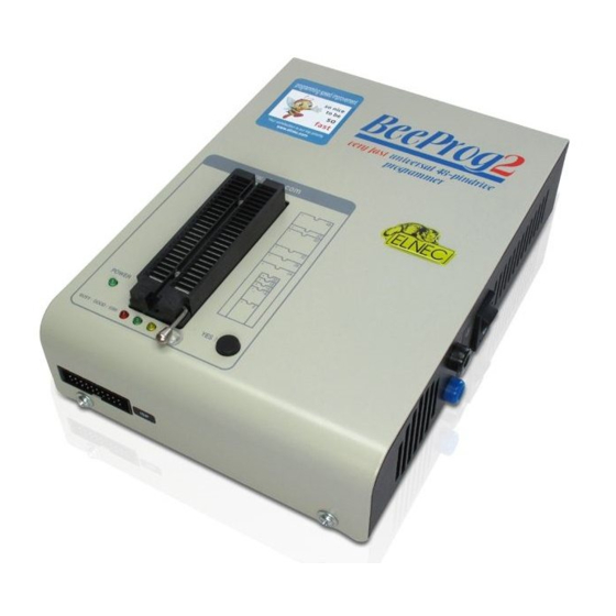
Very fast universal 48-pindrive Programmer with USB/LPT interface and ISP capability
BeeProg2C
Very fast universal 48-pindrive Programmer with USB interface and ISP capability
SmartProg2
Universal 40-pindrive Programmer with USB interface and ISP capability
Elnec s.r.o.
Presov, Slovakia
th
12
February 2021
1
Advertisement
Table of Contents
Troubleshooting

Related Manuals for Elnec BeeProg2


Summary of Contents for Elnec BeeProg2
- Page 1 Elnec s. r. o. User manual for BeeHive204 Very fast universal 4x 48-pindrive concurrent multiprogramming system with ISP capability BeeProg2 Very fast universal 48-pindrive Programmer with USB/LPT interface and ISP capability BeeProg2C Very fast universal 48-pindrive Programmer with USB interface and ISP capability...
- Page 2 Elnec s.r.o. assumes no responsibility for misuse of this manual. Elnec s.r.o. reserves the right to make changes or improvements to the product described in this manual at any time without notice. This manual contains names of companies, software products, etc., which may be trademarks of their respective owners.
-
Page 3: How To Use This Manual
User manual. Revisions are implemented in the context sensitive help before the printed User manual. Dear customer, thank you for purchasing one of the Elnec programmer. _____________________________________ Please, download actual version of manual from Elnec WEB site (www.elnec.com), if... -
Page 4: Table Of Contents
BeeProg2 / BeeProg2C elements..................... 37 Connecting BeeProg2 / BeeProg2C to the PC................. 38 Manipulation with the programmed device ..................39 In-system serial programming by BeeProg2 / BeeProg2C .............. 39 Multiprogramming by BeeProg2 / BeeProg2C ................. 41 Selftest and calibration check ......................41 Technical specification ........................ - Page 5 Elnec s. r. o. ISP (In-System Programming) ......................171 Other ..............................174 Troubleshooting and warranty ......................176 Troubleshooting ..........................177 If you have an unsupported target device ..................178 Warranty terms ..........................178...
- Page 6 Elnec s. r. o. Conventions used in the manual References to the control program functions are in bold, e.g. Load, File, Device, etc. References to control keys are written in brackets <>, e.g. <F1>. Terminology used in the manual: Device...
-
Page 7: Introduction
Introduction Introduction... - Page 8 IC tester with 48 powerful pindrivers. Using build-in ISP connector the programmer is able to program ISP capable chips in circuit. This design allows easily add new devices to the device list. BeeProg2 is a true universal and a true low cost programmer, providing one of the best "value for money" in today's market.
-
Page 9: Products Configuration
Introduction Products configuration Before installing and using your programmer, please carefully check that your package includes all next mentioned parts. If you find any discrepancy with respective parts list and/or if any of these items are damaged, please contact your distributor immediately. programmer USB cable LPT cable... -
Page 10: Pc Requirements
Elnec s. r. o. PC requirements Minimal PC requirements OS - Windows RAM [MB] 1000 1000 1000 1000 free disk space [MB] USB 2.0 high speed The "Minimal PC requirements" mean that the device programmer and SW will run at these conditions, but not with fully enjoyable experience. -
Page 11: Additional Services
Keep-Current is a subscription service, with which your Elnec programmer and documentation is up-to-date with the latest device support and control program's features. Elnec ships of a latest version of programmer software and updated user documentation (Keep-Current package). A Keep-Current service is your hassle-free guarantee that you are doing the highest quality programming on Elnec programmers, at minimal cost. -
Page 12: Quick Start
Elnec s. r. o. Quick Start... - Page 13 Double click on After start, control program PG4UW automatically scans all existing ports and searches for any connected Elnec programmer. Program PG4UW is common for all Elnec programmers hence PG4UW will try to find all supported programmers. Menu File is used for source files manipulation, settings and viewing directory, changes drives, changes start and finish address of buffer for loading and saving files and loading and saving projects.
- Page 14 Elnec s. r. o. 4. check, if the device is blank: click on 5. program device: click on 6. additional verify of device: click on...
-
Page 15: Detailed Description
Detailed description Detailed description... -
Page 16: Beehive204
Elnec s. r. o. BeeHive204... -
Page 17: Introduction
The chips are programmed at near theoretical maximum programming speed. BeeHive204 consist of four independent isolated universal programming sites, based on the BeeProg2 programmer hardware. Therefore the programming sites can run asynchronously (concurrent programming mode). Each programming module starts programming at the moment the chip is detected to be inserted in the socket properly - independently on the status of other programming sites. - Page 18 Selecting of device is performed by its class, by manufacturer or simply by typing a fragment of vendor name and/or part number. It is the same years-proven software, as is used for all other Elnec single-site programmers. Standard device-related commands (read, blank check, program, verify, erase) are boosted by some test functions (insertion test, signature-byte check), and some special functions (autoincrement, production mode - start immediately after insertion of chip into socket).
- Page 19 It is important to remember that in most cases new devices require only a software update, because the BeeHive204 is based on the truly universal (BeeProg2) programmer. With our prompt service you can have new devices can be added to the current list within hours! See AlgOR (Algorithm On Request) service and OnDemand software for details.
-
Page 20: Beehive204 Elements
Elnec s. r. o. BeeHive204 elements 1. 48 pin ZIF socket 2. work result LEDs 3. power/sleep LED of site 4. YES! Button 5. ISP connector 6. LED indicator power 7. power supply connector 8. power switch 9. "GND" connector can be used for grounding of the programmer "ESD wrist strap"... -
Page 21: Connecting Beehive204 To The Pc
BeeHive204 Connecting BeeHive204 to the PC Recommendation for connecting programmer to PC: 1. make ground connection between programmer and PC or other ground 2. connect programmer with PC via USB cable 3. connect power supply to programmer and turn on by power switch “8”. Manipulation with the programmed device After selection of desired device for your work, you can insert it into the open ZIF socket (the lever is up) and close socket (the lever is down). - Page 22 Elnec s. r. o. Description of ISP connector As ISP connector inside programmer is used 2 rows, 2,54mm (0.1“) pitch connector with 20 positions like 5103310-5 from TE connectivity or other compatible connector. Front view at ISP connector. H/L/read driver...
-
Page 23: Selftest And Calibration Check
(ISP) suffix after name of selected device. These specifications correspond with application notes published of device manufacturers. Used application notes you may find on www.elnec.com, section Support / Application Notes. Notes: Pin no. 1 is signed by triangle scratch on ISP cable connectors. - Page 24 Elnec s. r. o. Selftest of programmer Insert 48 pins diagnostic pod - type I into ZIF socket of the programmer. 48 pins diagnostic pod - type I must be inserted as 48 pins device. Run selftest of programmer in PG4UW (menu Programmer / Selftest).
-
Page 25: Technical Specification
BeeHive204 Technical specification Specification (BeeHive204 multiprogramming system) 4x universal programming sites (4x 48-pin DIL ZIF sockets), Beeprog2 programming core based operation result LEDs, LED power USB 2.0 high-speed compatible port line power input 100-240VAC/60W max. protection against surge and ESD on power supply input... - Page 26 Elnec s. r. o. ESD protection on each pin of ISP connector (IEC1000-4-2: 15kV air, 8kV contact) Only for ISP device: two output signals, which indicate state of work result = LED OK and LED Error (active level: min 1.8V) input signal, switch YES! equivalent (active level L: max 0.8V)
- Page 27 BeeHive204 SPLD/CPLD series: AMD, AMI, Atmel, Cypress, Gould, ICT, Lattice, National Semicond., Philips, STMicroelectronics, TI (TMS), Vantis, VLSI FPGA: Microsemi(Actel): ProASIC3, IGLOO, Fusion, ProASICplus, SmartFusion FPGA: Lattice: MachXO, MachXO2, LatticeXP, LatticeXP2, ispXPGA FPGA: Xilinx: Spartan-3AN Clocks: TI(TMS), Cypress Special chips: Atmel Tire Pressure Monitoring ATA6285N, ATA6286N; PWM controllers: Zilker Labs, Analog Devices;...
- Page 28 Elnec s. r. o. Microcontrollers NXP (Philips) ARM Cortex-Mx: LPC11xx, LPC11Cxx, LPC11Dxx, LPC11Uxx, LPC12xx, LPC12Dxx, LPC13xx, LPC17xx, LPC11Axx, LPC11Exx, LPC11xxLV, LPC18xx, LPC43xx, LPC8xx, EM7xx, series Microcontrollers NXP (Philips) UOC series: UOCIII, UOC-TOP, UOC-Fighter (TDA1xxxx) series Microcontrollers NXP (Philips) ARM7: LPC2xxx, MPT6xx, PCD807xx, SAF7780xxx series...
- Page 29 BeeHive204 Microcontrollers Atmel: AT89Cxxx, AT89Sxxx, AT89LSxxx, AT89LPxxx, AT90pwm, AT90can, AT90usb, AT90Sxxxx, ATtiny, ATmega, ATxmega series Microcontrollers Atmel AVR32: AT32UC3xxxx, ATUCxxxD3/D4/L3U/L4U series Microcontrollers Atmel ARM7: AT91SAM7Sxx, AT91SAM7Xxx, AT91SAM7XCxx, AT91SAM7SExx series; Microcontrollers TI (Chipcon): CC11xx, CC24xx, CC25xx, CC85xx series Microcontrollers Cypress: CY8C2xxxx Microcontrollers Elan: EM78Pxxx, EM6xxx series Microcontrollers EM Microelectronic: 4 and 8 bit series Microcontrollers Microchip PICmicro: PIC10xxx, PIC12xxx, PIC16xxx, PIC17xxx, PIC18xxx,...
- Page 30 Elnec s. r. o. For all supported devices see actual Device list on www.elnec.com. Package support support devices in DIP into socket of the programmer package support includes DIP, SDIP, PLCC, JLCC, SOIC, SOP, PSOP, SSOP, TSOP, TSOPII, TSSOP, QFP, PQFP, TQFP, VQFP, QFN (MLF), SON, BGA, EBGA, FBGA, VFBGA, UBGA, FTBGA, LAP, CSP, SCSP etc.
- Page 31 BeeHive204 Device operations standard: intelligent device selection by device type, manufacturer or typed fragment of part name automatic ID-based selection of EPROM/Flash EPROM blank check, read, verify program erase configuration and security bit program illegal bit test checksum interpret the Jam Standard Test and Programming Language (STAPL), JEDEC standard JESD-71 interpret the VME files compressed binary variation of SVF files security...
- Page 32 Elnec s. r. o. GENERAL operating voltage 100-240V AC rated, 90-264 VAC max., 47-63 Hz power consumption max. 60W active dimensions 361x234x56 mm (14.2x9.2x2.2 inch) weight (programmer) 3.5kg (7.7 lb) operating temperature 5°C ÷ 40°C (41°F ÷ 104°F) operating humidity 20%...80%, non condensing...
-
Page 33: Beeprog2 / Beeprog2C
BeeProg2 / BeeProg2C BeeProg2 / BeeProg2C... -
Page 34: Introduction
LPT port interface). If you need program some of the mentioned devices, please take a look at BeeProg2 programmer. BeeProg2 / BeeProg2C supports all kinds of types and silicon technologies of today and tomorrow programmable devices without family-specific module. You have freedom to choose the optimal device for your design. - Page 35 Built-in protection circuits eliminate damage of programmer and/or programmed device due environment or operator failure. All the inputs of the BeeProg2 / BeeProg2C programmer, including the ZIF socket, ISP connector, connection to PC and power supply input, are protected against ESD up to 15kV.
- Page 36 JTAG chain: JTAG chain (ISP-Jam) or JTAG chain (ISP-VME). Attaching of more BeeProg2 / BeeProg2C programmers to the same PC (through USB port) is achieved a powerful multiprogramming system, which support as many chips, as are supported by BeeProg2 / BeeProg2C programmer and without obvious decreasing of programming speed.
-
Page 37: Beeprog2 / Beeprog2C Elements
"ESD wrist strap" connector is place for attaching of ESD wrist strap 8. Power supply connector 9. LPT connector for PC BeeProg2 communication cable. For BeeProg2C after upgrade to BeeProg2 10. USB connector for PC BeeProg2 / BeeProg2C communication cable... -
Page 38: Connecting Beeprog2 / Beeprog2C To The Pc
Once the POWER LED lights with low brightness then the BeeProg2 programmer is ready to run. Next run the control program for BeeProg2. Caution! If you don't want to switch off your PC when connecting the BeeProg2, proceed as follows: When connecting the programmer to the PC: FIRST insert the communications cable and THEN the power-supply connector. -
Page 39: Manipulation With The Programmed Device
Don't unplug the target device from the ZIF socket during work with device (LED BUSY shine). In-system serial programming by BeeProg2 / BeeProg2C For general definition, recommendation and direction about ISP see section Common notes / ISP please. - Page 40 Elnec s. r. o. H/L/read driver pins 3, 5, 7, 9, 11, 13 of ISP connector pin 14 of ISP connector pin of ISP drivers in programmer pin of ISP drivers in programmer connector connector Float Read YES! Pull-up/ Pull-down...
-
Page 41: Multiprogramming By Beeprog2 / Beeprog2C
09185207813 from Harting or other compatible connector. BeeProg2 / BeeProg2C ISP cable Warnings: When you use BeeProg2 / BeeProg2C as ISP programmer, don’t insert device to ZIF socket. When you program devices in ZIF socket, don’t insert ISP cable to ISP connector. - Page 42 Elnec s. r. o. Selftest of programmer Insert 48 pins diagnostic pod - type I into ZIF socket of the programmer. 48 pins diagnostic pod - type I must be inserted as 48 pins device. Run selftest of programmer in PG4UW (menu Programmer / Selftest).
-
Page 43: Technical Specification
BeeProg2 / BeeProg2C Technical specification HARDWARE Base unit, DACs USB 2.0 high-speed compatible port, up to 480 Mb/s transfer rate FPGA based IEEE 1284 slave printer port, up to 1MB/s transfer rate (except BeeProg2C) on-board intelligence: powerful microprocessor and FPGA based state machine three D/A converters for VCCP, VPP1, and VPP2, controllable rise and fall time VCCP range 0...8V/1A... - Page 44 Elnec s. r. o. DEVICE SUPPORT Programmer, in ZIF socket NAND FLASH: Samsung K9xxx, KFxxx, SK Hynix (ex Hynix) HY27xxx, H27xxx, Toshiba TC58xxx, TH58xxx, Micron MT29Fxxx, (ex Numonyx ex STM) NANDxxx, Spansion S30Mxxx, S34xxx, 3D-Plus 3DFNxxx, ATO Solution AFNDxxx, Fidelix FMNDxxx, Eon Silicon Sol.
- Page 45 BeeProg2 / BeeProg2C Special chips: Atmel Tire Pressure Monitoring ATA6285N, ATA6286N; PWM controllers: Zilker Labs, Analog Devices; Multi-Phase ICs: IR(Chil Semiconductor); Gamma buffers: AUO, Maxim, TI, ... Microcontrollers MCS51 series: 87Cxxx, 87LVxx, 89Cxxx, 89Sxxx, 89Fxxx, 89LVxxx, 89LSxxx, 89LPxxx, 89Exxx, 89Lxxx, all manufacturers, Philips LPC series Microcontrollers Intel 196 series: 87C196 KB/KC/KD/KT/KR/...
- Page 46 SunplusIT, M-Square, QIXIN, Signetic, Tekmos, Weltrend, Amic, Cyrod Technologies, Ember, Ramtron, Nordic Semiconductor, Samsung, ABOV Semiconductor... PLD: Bipolar PALxxx * Only for BeeProg2 programmer NMOS/CMOS, 2708* PROM: AMD, Harris, National, Philips/Signetics, Tesla, TI Microcontrollers 48 series: 87x41, 87x42, 87x48, 87x49, 87x50 series...
- Page 47 Devices marked *2 are obsolete and some of them might require also PLD-1 additional module for programming The complicated devices with laborious implementation might belongs to the 'Paid ISP support' category For all supported devices see actual Device list on www.elnec.com. I.C. Tester TTL type: 54,74 S/LS/ALS/H/HC/HCT series CMOS type: 4000, 4500 series static RAM: 6116 ...
- Page 48 Devices in non-DIP packages up to 48 pins are supported by universal programming adapters - if it is technically possible on the BeeProg2 programmer. That means if reliability of operations when used universal programming adapter is below industrial standard, the specialized programming adapters are necessary to use.
- Page 49 BeeProg2 / BeeProg2C configuration and security bit program illegal bit test checksum interprete the Jam Standard Test and Programming Language (STAPL), JEDEC standard JESD-71 interprete the VME files compressed binary variation of SVF files security insertion test contact check ID byte check...
-
Page 50: Smartprog2
Elnec s. r. o. SmartProg2... -
Page 51: Introduction
SmartProg2 Introduction SmartProg2 is next member of new generation of Windows based Elnec universal programmers. Programmer is built to meet the demands of the development labs and field engineers to universal, but portable programmer. SmartProg2 is a small, fast and powerful programmer of all kinds of programmable devices. -
Page 52: Smartprog2 Elements
(like DHL) warrants customers very fast and secure delivery of ordered Elnec products. Products ordered before 10 a.m. (CET) will be dispatched the same working day (if products are in stock and the payment is done by online payment (CardPay, PayPal). -
Page 53: Connecting Smartprog2 To Pc
SmartProg2 6. USB connector for PC SmartProg2 communication cable 7. Power supply connector Power supply connector Note: Due to low power consumption of SmartProg2 in inactive state, it doesn't require power switch. When the power LED indicator glows with a low intensity the SmartProg2 is in inactive mode. -
Page 54: In-System Serial Programming By Smartprog2
(ISP) suffix after name of selected device. These specifications correspond with application notes published of device manufacturers. Used application notes you may find on www.elnec.com, section Support / Application Notes. Notes: Pin no. 1 is signed by triangle scratch on ISP cable connectors. -
Page 55: Selftest
SmartProg2 Note: H/L/read SmartProg2 driver H/L/read driver pin of ISP in programmer connector PU/PD driver in programmer C1=1nF, R1=1k3, R2=22k Selftest If you feel that your programmer does not react according to your expectation, please run the programmer selftest using Diagnostic pod, enclosed in the standard delivery package. Insert 40 pins diagnostic pod - type I into ZIF socket of the programmer. - Page 56 (VCCP) with both source/sink capability and voltage sense Note: The programmer is not capable to supply a target system from VCCP pin. If you have such demand, use please a BeeProg2 / BeeProg2C programmer. DEVICE SUPPORT Programmer, in ZIF socket...
- Page 57 (*1) - suitable adapters are available for non-DIL packages (*2) - there exist only few adapters for devices with more than 40 pins. Therefore think please about more powerful programmer (BeeProg2 / BeeProg2C), if you need to program devices with more than 40 pins see please actual DEVICE LIST on www.elnec.com...
- Page 58 Elnec s. r. o. program erase configuration and security bit program illegal bit test checksum security insertion test contact check ID byte check special auto device serial number increment statistic count-down mode Buffer operations view/edit, find/replace fill, copy, move, byte swap, word/dword split...
-
Page 59: Setup
Setup Setup... -
Page 60: Software Setup
The programmer package contains a CD with the control program, useful utilities and additional information. The permission to freely copy the content of the CD is granted in order to demonstrate how Elnec programmers work. For programmers connected through USB (LPT) port, control program requires correctly... - Page 61 Setup Step 3. Click on “Next” button Step 4. For default setting you click on “Next” button. Setup will be continuing with Step 6. For change default setting you click on “Custom” and then on “Next” button.
- Page 62 Elnec s. r. o. Step 5. To change default folder click on “Browse” button, select the destination folder. Then click on “Next” button Step 6. Check if “Install Multiprogramming control support” is selected. Change default setting, if you want. Then click on “Next” button.
- Page 63 Setup Step 7. Check your settings and then click on “Install” button Step 8. Installation process will start.
-
Page 64: Hardware Setup
In order to exploit all the capabilities of programmer we recommend using the latest version of PG4UW. You may download the latest version of programmer software (file pg4uwarc.exe) from our Internet site www.elnec.com, part download. Copy pg4uwarc.exe to a temporary directory, disconnect programmer from PC and then launch it. - Page 65 Setup automatically or manually. To detect programmer correctly, control program installation CD must be inserted to computer's CD-ROM drive and following steps have to be done: Step 1. Directly connect USB (LPT) cable to type B USB (LPT) port on programmer. Step 2.
- Page 66 Elnec s. r. o. PG4UW...
-
Page 67: Pg4Uw-The Programmer Software
PG4UW PG4UW-the programmer software Program PG4UW is common control program for all Elnec programmers, which works with all versions of MS Windows from Windows XP to Windows 10, 32-bit and 64-bit. Using the programmer software The control program delivered by Elnec, included on the CD in your package, is granted to be free from any viruses at the moment of delivery. - Page 68 Elnec s. r. o. Description of the user screen Windows program PG4UW Toolbars Under main menu are placed toolbars with button shortcuts of frequently used menu commands. Toolbars are optional and can be turned off by menu command Options / View.
- Page 69 PG4UW device and buffer address ranges by menu command Device / Device options / Operation options. Panel Addresses also contains some advanced information about current status of Split, Serialization and buffer checksum. For more information about each of the options, please look Split - menu Device / Device options / Operation options Serialization - menu Device / Device options / Serialization Checksum - menu Buffer / Checksum at section Checksum displayed in main window...
-
Page 70: File
Elnec s. r. o. List of hot keys <F1> Help Calls Help <F2> Save Save file <F3> Load Load a file into the buffer <F4> Edit Viewing/editing of buffer <F5> Select/default Target-device selection from 10 last selected devices list <Alt+F5>... - Page 71 PG4UW ASCII SPACE format Very simple hex file format similar as ASCII HEX without checksum field, without start (STX) and end (ETX) characters. Each data byte is represented as 2 hexadecimal characters, and is separated by white space from all other data bytes. The address field is separated by white space from data bytes.
- Page 72 Elnec s. r. o. If the checkbox Swap bytes is displayed, the user can activate function of swapping bytes within 16bit words (or 2-byte words) during reading of file. This feature is useful especially when loading files with Motorola representation of byte order in file (big endian). Standard load file is using little endian byte order.
- Page 73 PG4UW Notes: Since the value of negative offset is subtracted from real address, the result of subtraction can be negative number. Therefore take care of correct setting of this value! We recommend automatic set of negative offset in special cases only. This option contains a heuristic analyze, which can treat some data in file incorrectly.
- Page 74 Elnec s. r. o. MOTOROLA, MOS Technology, Tektronix, Intel (extended) HEX, ASCII space, JEDEC and POF. If the checkbox Swap bytes is displayed, the user can activate function of swapping bytes within 16bit words (or 2-byte words) during writing to file. This feature is useful especially when saving files with Motorola representation of byte order in file (big endian).
- Page 75 PG4UW Enter job identification dialog The dialog will be showed when loading protected project files. It contains two editable fields: Operator identification this parameter will be used to identify programmer's operator. Operator ID must be at least 3 chars. User has to enter Operator identification value, because it is mandatory parameter, when creating Job Report for protected project.
- Page 76 Elnec s. r. o. project file is recently loaded. There is also recommended to use this checkbox along with active Protected mode. When the request of project file unique ID is active, the software indicates this by label (ID) next to project file name in bottom status line in control program main window.
-
Page 77: Buffer
PG4UW User can directly edit user defined project description only. Device name, manufacturer, and project date are generated automatically by program. File / Load encryption table This command loads the data from binary file from disk and it saves them into the part of memory, reserved for an encryption (security) table. - Page 78 Elnec s. r. o. Shift+F3 load data from binary file to buffer. This command is available for secondary buffers only. For more information see notes for save buffer data command (Shift+F2) above. move block is used to move specified block of data in current buffer on new address.
- Page 79 PG4UW of all versions of Windows. User can define any text editor for example wordpad.exe, which is able to work with large text files. In user defined text editor user can print or save to file selected block of buffer. The external editor path and name is saved automatically to disk.
- Page 80 Elnec s. r. o. Buffer / Fill block Selecting this command causes filling selected block of buffer by requested hex (or ASCII) string. Selecting option "Allow address history logging" activates saving of recently confirmed values. These are saved for each device separately; count is limited to last 15 items.
- Page 81 PG4UW Swap 2-bytes Swap 4-bytes Swap Mirror bits Original Address inside 16-bit inside 32-bit nibbles inside Data words words inside bytes bytes 0000h 0001h 0002h 0003h 0004h 0005h 0006h 0007h b0, b1, b2 ... means original buffer byte values from addresses 0, 1, 2... b0n, b1n, b2n...
- Page 82 Elnec s. r. o. Default address range is set according to buffer range of selected device. Selecting option "Maintain last inserted values" causes that for the next time you open this dialog, previously confirmed values will be reloaded as default.
- Page 83 PG4UW Insert at address Address in buffer where a result of chosen checksum is written, when the Calculate & insert was executed. Address can not be specified inside the range <From address> to <To address>. Address is always defined as Byte address. Size Size of chosen checksum result, which will be written into the buffer.
- Page 84 Elnec s. r. o. from Main Checksum settings. So Checksum calculator options are equal to recent Main Checksum options after starting software or loading project. Dialog Checksum options offers also useful functions such as Reset to defaults, or Copy Checksum calculator settings to Main Checksum settings, and vice versa.
-
Page 85: Device
PG4UW Device dependent checksum - applies for some devices, e.g. STMicroelectronics's STM8 family The checksum modes for main checksum can be set in pop-up menu by clicking on label checksum in main program window or by menu shortcuts Shift+Ctrl+1 for Byte sum (x8), Shift+Ctrl+2 for Word sum Little Endian (x16) Shift+Ctrl+3 for Word sum Big Endian (x16) etc... - Page 86 Elnec s. r. o. Fragments of query are by default compared using AND logic, but there is an option to switch to OR logic if needed. Matching results have computed relevancy according to how close the match is (with respect to AND/OR logic). By default, results are ordered by relevancy.
- Page 87 PG4UW If more devices with identical chip ID and manufacturer's ID were detected, the list of these devices will be displayed. A corresponding device can be chosen from this list by selecting its number (or manufacturer name) from list and press <Enter> (or click OK button). Press a key <Esc>...
- Page 88 Elnec s. r. o. Split type Device Buffer Address assignment None Device [ADDR] Buffer [ADDR] Even Device [ADDR] Buffer [2*ADDR] Device [ADDR] Buffer [1+ (2*ADDR)] Device [ADDR] Buffer [4*ADDR] Device [ADDR] Buffer [1+(4*ADDR)] Device [ADDR] Buffer [2+(4*ADDR)] Device [ADDR] Buffer [3+(4*ADDR)]...
- Page 89 PG4UW group Command execution: blank check before programming (default DISABLE) erase before programming (default DISABLE) verify after reading (default ENABLE) verify (ONCE, TWICE) verify options (nominal VCC +/-5% nominal VCC +/-10% VCCmin…VCCmax) group Target system power supply parameters This group is available in ISP mode for some types of devices. It contains following settings: Enable target system power supply - enables supplying of target system from programmer.
- Page 90 Elnec s. r. o. Disable test supply voltage - disables measure and checking supply voltage of programmed device, set in Supply voltage edit box, before action with device. Delay after reset active - this parameter determine delay after Reset signal active to start action with device.
- Page 91 PG4UW Note: Calling of new serial number request before programming can be suppressed in case of previous unsuccessful device programming result by option Serial number usage if programming action fails: when Reuse generated serial number for next programmed device option is selected, request for new (next) serial number is suppressed in case of unsuccessful previous device operation result.
- Page 92 Elnec s. r. o. means the serial number is written directly to buffer. If the serial number has more than one byte length, it can be written in one of two possible byte orders. The byte order can be changed in Save to buffer item.
- Page 93 PG4UW Split serial number: unchecked (empty box) Following values will be written to device: The 1st device Address Data 007FFF0 xx xx xx xx xx xx xx xx xx xx xx xx 00 00 00 16 The 2nd device Address Data 007FFF0 xx xx xx xx xx xx xx xx xx xx xx xx 01 00 00 16 The 3rd device...
- Page 94 Elnec s. r. o. Let’s assume we want to write serial number 1234ABCDH as part of four RETLW instructions to device PIC. The highest Byte of serial number is the most significant Byte. We want to write the serial number to device program memory at address 40H. Serial number split us very useful in this situation.
- Page 95 PG4UW The second device will have: Address Data 0000040 34CE 34AB 3434 3412 xxxx xxxx xxxx xxxx Next devices will have same format of serial number, of course incremented by 1 for each device. Example 2.b Use of serialization split with NOP instructions for Microchip PIC24FJ256 devices Device PIC24FJ256 has 24 bit wide instruction word.
- Page 96 Elnec s. r. o. Next devices will have same format of serial number incremented by 1 for each device. Example 3: Following example uses the same serialization options as Example 2a; instead the serial number Split gap is set to 2 and 3.
- Page 97 PG4UW "Classic" From-file mode: the serialization file has serial values directly included. Serialization data are then read directly from serialization file to buffer on address specified in the file. Classic From-file mode is indicated in main window and info window of PG4UW control program on panel "Serialization"...
- Page 98 Elnec s. r. o. Delete used file: Program deletes used serialization data file(s) Directory This option is available in playlist From-file serialization mode when option "Move used file to specified directory" is selected. User can specify target directory, into which used serialization data files will be moved.
- Page 99 PG4UW addr - Addr defines buffer address to write data following the address. byte0...byten, byte0...bytem, byte0...bytek - Bytes arrays byte0...byten, byte0...bytem and byte0...bytek are defining data, which are assigned to write to buffer. Maximum count of bytes in one data field following the address is 64 bytes.
- Page 100 Elnec s. r. o. In the example file six serial values with labels „nav1“, „nav2“, ...“nav6“ are defined. Each value is written to buffer on address $A7890. All values have size 6 bytes. The line with „nav6“ label has also second value definition, which is written to buffer on address $FFFF6 and has size 10 bytes, i.e.
- Page 101 PG4UW The typical path can look like this: C:\Program Files\Elnec_sw\Programmer\Examples\Serialization\fromfile_playlist_example\ You can test the serialization by following steps: 3. start PG4UW 4. you need to have our programmer connected and correctly found in PG4UW 5. select wished device, the best are devices with erasable memory, (not OTP memory) 6.
- Page 102 Elnec s. r. o. Serialization generator Specifies the path and name for the executable file which will generate serialization data file, for example c:\serialization\generator.exe. First serial number This option is required to specify the initial serial number that will be passed to custom generator serialization program.
- Page 103 PG4UW generator.exe - N<serial number> - E<serial number> N<serial number> Specifies current serial number, that generator has to use to create proper serial data file. Generator must return the same value at line T01:<serial number> in data file. More information about serialization .dat file format is available in the next section, few lines lower.
- Page 104 Elnec s. r. o. Example: Typical serialization data file: T01:000005 T02:001006 T03:99 T04: :0300000000096B89 :03000300000005F5 :02000C005A0197 :01003F004F71 :00000001FF The file consists of following information: line T01 - current serial number 000005h line T02 - ending (last) serial number 001006h (this value will be used as new current serial...
- Page 105 PG4UW 4. Device programming 5. Device verification 6. Operation result check. This is fully managed by PG4UW control program. Serialization generator does not have to do any operation according to operation result. Control program will call serialization generator with required command line parameters. OK - PG4UW makes request for next serial number.
- Page 106 Elnec s. r. o. Check box Count down sets Count down activity (enable or disable). Edit box following the Count down check box defines initial number of count down counter, from which count down starts. Statistics dialog can be also opened by pressing right mouse button on Statistics panel and clicking displayed item Statistics.
- Page 107 PG4UW For multiprogramming PG4UWMC software, the statistics information is saved to Job Summary report. Device / Device options / Associated file This command is used for setting associated file with current device. This is a file, which can be automatic loaded to buffer after device is selected from default devices select list or by start control program.
- Page 108 Elnec s. r. o. Settings in dialog General options (menu Options / General options) of PG4UW in tab Errors allows to control, how to write the found errors to user specified report file. Also first 45 found errors are written to Programmer activity log.
- Page 109 PG4UW RAM test, advanced (optional). "Walking one" and "Walking zero" are common terms, who need explanation can study: http://www.google.com/search?q=memory+test+walking+one http://www.google.com/search?q=memory+test+walking+zero Notes: It is possible to select a delay between write operation and succeeding verify of programmed data (at condition the device is supplied) in intent to detect 'leak' of the bits. Programmer hasn't capability to detect errors like too big current on the signal pins or such "analog"...
- Page 110 Elnec s. r. o. The Jam Composer is a program, generally written by a programmable logic vendor, that generates a Jam file (.jam) containing the user data and programming algorithm required to program a design into a device. The Jam Player is a program that reads the Jam file and applies vectors for programming and testing of devices in a JTAG chain.
- Page 111 PG4UW Procedures Program flow executes statements from each procedure. Procedures may be optional and recommended. Recommended procedures are marked implicitly. You can enable or disable procedures according to your needs. Jam Player executes only marked procedures. Other procedures are ignored. Number of procedures is different, it depends on Jam file. Accept selected action with appropriate procedures which are marked.
- Page 112 Elnec s. r. o. Information about converting JED file to Jam STAPLE file for XILINX devices: install Xilinx Integrated Software Environment (ISE) 6.3i software free download: WebPACK_63_fcfull_i.exe + 6_3_02i_pc.exe (315MB or so) run Xilinx ISE 6/Accessories/iMPACT in dialog “Operation Mod Selection: What do you want to do first?” choose: “Prepare Configuration Files”,...
- Page 113 PG4UW Converting PDB file to Jam STAPL file for ACTEL devices: install software tool FlashPro (component of Actel Libero tool suite or can be downloads from <http://www.actel.com> as a standalone version) run FlashPro click the New Project button or from the File menu choose New Project and type in the name of your project in the Project Name field.
- Page 114 Elnec s. r. o. system through ISP connector. It is indicated by [PLCC44] (VME) or (ISP-VME) suffix after name of selected device in control program. Multiple devices are possible to program and test via JTAG chain: JTAG chain (ISP-VME). More information on the website: http://www.latticesemi.com...
-
Page 115: Programmer
PG4UW Programmer Menu Programmer includes commands used for work with programmers. Programmer / Find programmer Select programmer and communication parameters in PG4UW software. Programmer in this section is shown list of all programmers available in current version of PG4UW software. Select the programmer which you want to connect. If option Search all is selected, then PG4UW will try to find any of supported programmers and first found programmer will be connected. - Page 116 Elnec s. r. o. Connecting the programmer via USB: Select the programmer with USB connection capability, e.g. BeeProg2. This will enable USB port settings. Select USB port and click Find button. Connecting the programmer via LPT port: Select the programmer with LPT connection capability, e.g. BeeProg2. This will enable LPT ports settings.
- Page 117 PG4UW The bar-graph at the bottom of ‘Credit box' button also indicates status of credits on attached Credit box(es) as next: green bargraph 85% of total credits available yellow bargraph credit box button 50% of total credits available red bargraph credit box button 10%, of total credits available no bargraph credit box button 0% of total credits available (depleted)
- Page 118 Elnec s. r. o. See please the Application note Usage of Credit box for devices in 'Paid ISP support' category at our web site for details. Programmer / Module options This option is used for multiple socket programmers for defining MASTER socket and activity of each socket.
- Page 119 PG4UW Button Reset Automatic YES! parameters to default state, click this button to discard all parameters set by Automatic YES! parameters setting wizard. Default parameters preset in PG4UW software will be used. The Device removal hold off time is time period between you removed device from the ZIF socket and the time when software starts to check the socket for new device inserted.
- Page 120 Elnec s. r. o. Selftest without Diagnostic pod: selects selftest without Diagnostic pod (or module) additional loop(s). Selftest with Diagnostic pod: selects selftest with Diagnostic pod (or module) additional loop(s). Execute: clicking this button will start executing selected selftest. Cancel: clicking this button will finish selftest and return to application's main screen.
- Page 121 PG4UW Schematic of 40 Pins Diagnostic pod - Type I (if you are in hurry): Schematic of 48 Pins Diagnostic pod - Type I (if you are in hurry):...
- Page 122 Elnec s. r. o. Programmer / Selftest ISP connector Command executes a selftest of ISP connector of current programmer using diagnostic pod for ISP connectors. Selftest can be executed once or multiply times. It can be selected in dialog, shown below.
- Page 123 Diagnostic pod for ISP connectors #2 is used for testing 20 pins ISP connector of programmers. Diagnostic pod for ISP connector #2 is available as standard accessory for BeeHive208S, BeeHive204, BeeProg2 and BeeProg2C. The order number: 70-0680. Schematics of Diagnostic pod for ISP connectors #2 (if you are in hurry): Sequence for testing 20 pins ISP connector: 1.
- Page 124 Programmer / Calibration test Command executes test of programmer's calibration values using 48 Pins Calibration test pod, Type I, which is optional accessories for BeeHive204, BeeProg2 and BeeProg2C. The order number: 70-0438. There are tested voltage levels of TTL drivers, VCCP, VPP1 and VPP2 voltages on each pin of ZIF socket.
-
Page 125: Options
PG4UW Options The Options menu contains commands that let you view and change various default settings. Options / General options General options dialog allows user to control and set variety of PG4UW program options. The options can be saved to PG4UW configuration file when closing PG4UW application, or anytime by command Options / Save options. - Page 126 Elnec s. r. o. File format masks is used for setting file-name masks to use as a filter for file listing in File / Save and File / Load file window for all file formats. Mask must contain one of wildcards (*, ?) at least and must be applied correctly by syntax.
- Page 127 PG4UW Colors and LEDs Colors of the work result LEDs of programmer: Standard color scheme (ERROR=red, BUSY=yellow) Former color scheme (ERROR=yellow, BUSY=red) Note: These settings are available only for newer types of programmers. If you can't see mentioned settings in menu, or menu is not enabled for editing, your programmer doesn't support LED color scheme customization.
- Page 128 Elnec s. r. o. Append default, adds Log window reports into existing Log file. If file does not exist, the new file will be created Checkbox Add date information to Log file name (to create new log file each new day) allows user to have different Log file for each day.
- Page 129 PG4UW Job Report contains following information: project name project date Protected mode status PG4UW software version programmer type and serial number start time of executing the Job (it means time when Load project operation was performed) end time of executing the Job (time of creating the Job Report) device name device type checksum...
- Page 130 Elnec s. r. o. Example 2: Let's use the conditions from Example 1, but assume there is already one report file present. Name of this file is d:\job_reports\job_report_000_myproject.jrp The final Job Report file name of new report will be: d:\job_reports\job_report_001_myproject.jrp Note: The order inside file name is incremented by 1.
- Page 131 PG4UW Default TCP communication settings for remote control are: Port: telnet Address: 127.0.0.1 or localhost Address setting applies for PG4UW (Client) only. Port setting applies for PG4UW (Client) and also for Server application. Default settings allow using remote control on one computer (address localhost). PG4UW (Client) and remote control Server have to be installed on the same computer.
- Page 132 Elnec s. r. o. Options / View / Additional toolbar Choose this command to show or hide the Additional toolbar. Options / View / Device options before device operation Choose this command to enable/disable display of Device options before device operation is confirmed.
- Page 133 PG4UW This allows you and others to view content of buffer and Alt+S settings, but not edit (due to active Protected mode). Activate this option, if you wish to disable also viewing of buffer content in Protected mode. In this case, we recommend activating also option Encrypt project file (with password). For details see File / Save project.
- Page 134 Elnec s. r. o. There is menu command - Options / Switch to Operator Mode… that allows using Operator mode in application PG4UWMC. After selecting the menu Options / Switch to Operator Mode…, password dialog appears. User has to enter password twice to confirm the password is correct.
- Page 135 PG4UW Multi-projects Multi-project is special feature which provides possibility to run any sequence of operations with any device, based on informations saved during creation of sub-projects and multi- project itself. In practice, using Multi-projects you are able to: comfortably program multi-chip devices configure and run any sequence of device operations (e.g.
- Page 136 Elnec s. r. o. Select of sub-projects and build final Multi-project file Load of existing Multi-project file *1 Start device operation of recent Multi-project *1 Note: Existing Multi-project file can be loaded from main menu of PG4UW using menu File / Load project or from Multi-project Wizard by Load multi-prj command.
- Page 137 PG4UW Note: There is possible to create Multi-project from any classic project files. So association with Master device is not mandatory. It is only on user's consideration how to combine correct sub-devices (sub-projects) into one Multi-project. This feature can be especially useful when using ISP programming of devices in JTAG chain with different projects defined.
-
Page 138: Help
Elnec s. r. o. For multiprogramming by PG4UWMC or standalone programmer: Load Multi-project by Load project menu. Run wished device operation by one of available device operation buttons (Blank, Verify, Program, Erase); mostly Program device operation is used. Selected device operation is executed as sequence of sub-project loading and consequent sub-device programming for each sub-device defined in Multi-project. - Page 139 Help. Note: Information provided in this manual is intended to be accurate at the moment of release, but we continuously improve all our products. Please consult manual on www.elnec.com. Since the Help system is continuously updated together with the control program, it may contain information not included in this manual.
- Page 140 Elnec s. r. o. Programmer / Create problem report Command Create problem report is used for writing more particular diagnostic information to Log window and consequently for creating a Problem report information file from Log window. The created file can be opened and content can be read by any text editor.
-
Page 141: Pg4Uwmc
PG4UWMC PG4UWMC... - Page 142 Elnec s. r. o. Program PG4UWMC is used for fully parallel concurrent device multiprogramming on more programmers or on multiprogramming capable programmers connected to USB/LAN ports of one or more computers. PG4UWMC is focused to the easy monitoring of high-volume production operations. Operator-...
- Page 143 PG4UWMC Main window of PG4UWMC consists of following parts: Menu and tool buttons Menu and tool buttons allow access to most of PG4UWMC functions. Tool button Settings Button is used to open PG4UWMC Settings dialog. Settings dialog is described bellow. Panels Site #1, Site #2...
- Page 144 Elnec s. r. o. Button Stop ALL Button is used to stop currently running device operations on all connected Programmer Sites. Button Help Button is used to display this help. Button Start remote control of programmer(s) The button is available for automated programmers only and only if Use Site #1 project for all Sites in PG4UWMC Settings dialog/Multiprogramming/Project options is checked.
- Page 145 PG4UWMC Additional serialization file is always placed to the directory "serialization\" into the control program's directory. Example: Project file name: my_work.prj Control program's directory: c:\Program Files\Programmer\ The additional serialization file will be: c:\Program Files\Programmer\serialization\my_work.prj.sn Additional serialization file is created and refreshed after successful device program operation. The only requirement for creating additional serialization file is load project with serialization turned on.
- Page 146 Elnec s. r. o. Job report is generated in following cases: user command Load project is selected closing or disconnecting programmer sites is selected closing the PG4UW device Count down counter reaches 0 (finished status) manually by user, when menu "File / Job Report" is used The Job report is generated for recently loaded project file, only when statistics value of Total is greater than 0.
- Page 147 PG4UWMC support to customize Start-End device addresses. Some devices (for example NAND FLASH) have customizable sector or page count/range, and the "whole device" means range of device specified by these options. Device / Program This command executes device programming. The control program reports a result of this action by messages in INFO window and LOG.
- Page 148 Elnec s. r. o. Note: Red colored programmers indicate that there are some sites which are expected to be present, but cannot be found. These sites are listed in "Not found" column. Otherwise the column is hidden. Programmer / Credit box info...
- Page 149 PG4UWMC Keep "Load project" operation allowed is set to inactive state by default - it means the Load project operation button and menu will be disabled when Operator mode is active. If the option is enabled (checked), the Load project operation button and menu will be allowed in Operator mode.
- Page 150 Elnec s. r. o. Options / General options PG4UWMC General options dialog is used to set or display configuration options of PG4UWMC. panel Multiprogramming There is table which contains following columns: column Sites contains checkboxes with Site numbers #1, #2, #3, #4 used to enable/disable...
- Page 151 PG4UWMC which allows to program different data to different types of devices at the same time in each Site. Checkbox Auto-load recent project(s), when connecting Sites When checked, recent project(s) are automatically loaded every time programmer Sites (their PG4UWs) are started and connected to PG4UWMC. Sites connecting to PG4UWMC can be performed by two ways: automatically, after starting of PG4UWMC (see information about checkbox Auto-connect Sites bellow)
- Page 152 Elnec s. r. o. operation results. Multiprogramming system generates few of Log files. One main Log file of program PG4UWMC and Log files for each of running Programmer Sites. Each Site has its own one Log file. The name of Site's Log file has the same prefix as the name of Log file specified in edit box Log file.
- Page 153 PG4UWMC text included in Log file will be truncated. When the option is unchecked, the size of Log file is unlimited, respectively is limited by free disk space only. option Maximum Log file size specifies the maximum size of Log file in kB option Amount of truncated text specifies the percentage of Log file text, which will be truncated after Maximum Log file size is reached.
- Page 154 Elnec s. r. o. Job Report dialog settings are in dialog PG4UWMC Settings (menu Options / Settings) in tab Job Report. Following options are available for Job Report: When the checkbox Automatically save Job Report file is checked, the Job Report will be...
- Page 155 PG4UWMC When Automatically save Job Report file setting is set, no Job Report dialogs appears when generating Job Report. Newly generated Job Report is saved to file without any dialogs or messages (if no error occurs while saving to file). If the checkbox Automatically save Job Report file is unchecked, the PG4UWMC will show Job Report dialog every time needed.
- Page 156 Elnec s. r. o. new device and runs last executed operation without pressing any key or button. An insertion of device into ZIF is displayed on the screen. Repeated operation executing will be canceled by pressing key <Esc> during waiting for insert/remove a device to/from ZIF.
- Page 157 PG4UWMC software wait for inserting a new device mode by blinking with the LED Busy. After an operation with a device is done, one of the status LEDs (OK or Error) lights, in dependence on the result of previous operation and the LED Busy is blinking. If the program detects removal of a device from ZIF socket, then the status LED goes off, but the LED Busy is still blinking to indicate readiness of the program to repeat last operation with new device.
- Page 158 Elnec s. r. o. Timer refresh rate defines how often the PG4UWMC program will request status information from running Programmer Sites. Status information means current device operation type, progress, result and so on. Current status information is displayed in main window of PG4UWMC.
- Page 159 PG4UWMC A combination of partial operations is counted as one operation only. For example, a Read operation including Verify after Read is one operation. A Program operation including Erase and/or Verify operations is counted as one operation. Check box Enable Count down sets Count down activity (enable or disable). Edit box following the Count down check box defines initial number of count down counter, from which count down starts.
-
Page 160: Help
Help. Note: Information provided in this manual is intended to be accurate at the moment of release, but we continuously improve all our products. Please consult manual on www.elnec.com. Since the Help system is continuously updated together with the control program, it may contain information not included in this manual. - Page 161 PG4UWMC There are two options/buttons for Create problem report: Button Yes, last days logs. This option creates smaller size Problem report .zip file, containing log files from last week. Log files included into .zip are all truncated to maximum file size about 1MB. Button Yes, all days logs available.
-
Page 162: Common Notes
Elnec s. r. o. Common notes... -
Page 163: Maintenance
Common notes Maintenance We recommend following the instructions and precautions herein to achieve high reliability of the programmer for a long period of time. The programmer maintenance depends on character and amount of its use. Regardless, the following recommendations are generally accepted: Do not use and store the programmer in dusty places. -
Page 164: Software
Software PG4UW is common control program for all of the Elnec programmers. During work with this SW you can find some features and menu items that are not available for currently selected programmer. - Page 165 Common notes /Saveproject:... is equivalent to user selected command Save project in PG4UW control program. Please note, the file name Windows conventions must be fulfilled. It means also, that when file name contains spaces, the command line parameter must have the file name bounded inside quotation marks.
- Page 166 Elnec s. r. o. Available command line parameters: /Axxx check programmer present on LPT port with address xxx only example: /A3bc /SPP force PC <-> programmer communication in unidirectional mode Available command line parameters for starting program PG4UW in demo mode Demo mode is useful in situations, when no programmer device is available.
- Page 167 Common notes /Close This parameter has sense together with /Program parameter only, and makes program PG4UW to close automatically after device programming is finished (no matter if operation was successful or not). /Saveproject:<file_name> The command is used to save currently selected device type, buffer contents and configuration to project file.
- Page 168 Elnec s. r. o. The INDEX parameter specifies the order of buffer, where data will send. The main buffer has index '1'. The first secondary buffer has index '2', etc. Please note, the secondary buffer(s) is(are) available for some kinds of devices only (e.g. Microchip PIC16F628). The kind of buffer indexed by parameter buffindex depends on order of buffer in application PG4UW in dialog View/Edit buffer.
- Page 169 Common notes 5. when device programming completes, pg4uwcmd.exe is closed and is returning ExitCode depending on load file and device programming results in pg4uw.exe. When all operations were successful, pg4uwcmd.exe returns 0, otherwise returns value 1 or more. Example 2: pg4uwcmd.exe /program:noanyquest /prj:c:\emproject.eprj The operations are the same as in Example 1;...
-
Page 170: Hardware
Because BeeHive204, BeeProg2 and BeeProg2C have internal power supply, follow these special precautions: Circuit breakers (overcurrent protection) must be a part of building electrical installation. -
Page 171: Isp (In-System Programming)
(for example use VGA connector). Any devices connected to target system must be connected to common earth point too. Direction of connect Elnec ISP programmer to target system: During in-system programming you connect two electrical devices – ISP programmer and target system. - Page 172 In-system programming. Condition is exactly respecting these application notes. Applications notes, which Elnec use in ISP programmers, are published in www.elnec.com, section Support / Application Notes. Please, read some notes for following recommended circuits.
- Page 173 Common notes Elnec recommended circuit for AT89Sxxx: ISP connector target device target system DATA IN DATA OUT target VCC check only 1u/10V MOSI MISO 1N4148 AT89Sxxx 100k reset circuit ® PICmicro microcontrollers This interface corresponds with Microchip application notes TB013, TB017, TB016: How to Implement ICSP Using PIC16CXXX OTP (PIC12C5XX OTP) (PIC16F8X Flash) MCUs.
-
Page 174: Other
Note: External reset circuit is necessary only if VDD power-up slope is too slow. Other There is needful for regular running of control program for any Elnec programmer that printer port, on which is programmer connected, must be reserved for this programmer only. - Page 175 Common notes The short description, how to see LPT ports present in operating system: 1. click to "Start" menu 2. click with right mouse button to "My computer" item and select menu "Properties 3. in the "System properties" dialog select "Hardware" page and click to "Device manager" button 4.
-
Page 176: Troubleshooting And Warranty
Elnec s. r. o. Troubleshooting and warranty... -
Page 177: Troubleshooting
Send the completed form by mail or fax to Elnec (fax number in the control program, menu Help / About) or to your local dealer. If you send the form by fax please use black ink, a good pen and large letters! E-mail - Use "DEVICE PROBLEM REPORT"... -
Page 178: If You Have An Unsupported Target Device
(BeeHive204, BeeProg2, BeeProg2C and SmartProg2) from the date of purchase. This warranty is limited to 25,000-cycles on DIL ZIF socket or 10,000-cycles on other ZIF sockets). If the product is diagnosed as defective, Elnec s.r.o. - Page 179 Troubleshooting and warranty Elnec has used its best efforts to develop hardware and software that is stable and reliable. Elnec does not guarantee that the hardware and software are free of "bugs", errors or defects. Elnec's liability is always limited to contract's net value paid by a buyer.
Need help?
Do you have a question about the BeeProg2 and is the answer not in the manual?
Questions and answers