Table of Contents
Advertisement
Quick Links
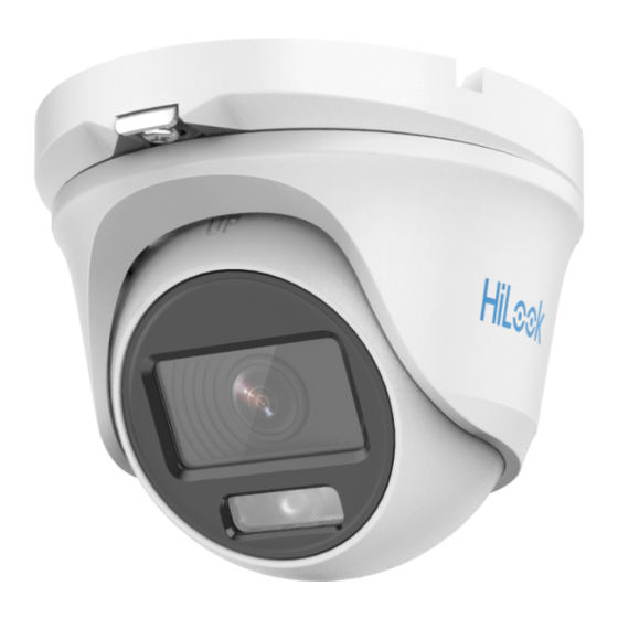
2MP ColorVu Audio Fixed
Turret & Bullet Camera
User Manual
Thank you for purchasing our product. If there are any
questions, or requests, do not hesitate to contact the
dealer.
This manual applies to the models below:
This manual may contain several technical mistakes or
printing errors, and the content is subject to change
without notice. The updates will be added to the new
version of this manual. We will readily improve or
update the products or procedures described in the
manual.
Type
Type I
Type II
Type III
Type IV
Type V
HiLook Series
User Manual
Model
THC-T129-PS
THC-T129-MS
THC-T229-MS
THC-B129-PS
THC-B129-MS
THC-B229-MS
01010020220720
Advertisement
Table of Contents

Related Manuals for HIKVISION THC-T129-PS


Summary of Contents for HIKVISION THC-T129-PS
- Page 1 Thank you for purchasing our product. If there are any questions, or requests, do not hesitate to contact the dealer. This manual applies to the models below: Type Model Type I THC-T129-PS Type II THC-T129-MS Type III THC-T229-MS THC-B129-PS Type IV...
- Page 2 With the philosophy of “Technology for the Good”, Hikvision requests that every end user of video technology and video products shall comply with all the applicable laws and regulations, as well as ethical customs, aiming to jointly create a better community.
- Page 3 establishing and constantly optimizing network security. Video products have made great contributions to the improvement of social security around the world, and we believe that these products will also play an active role in more aspects of social life. Any abuse of video products in violation of human rights or leading to criminal activities are contrary to the original intent of technological innovation and product development.
-
Page 4: Regulatory Information
Regulatory Information FCC Information Please take attention that changes or modification not expressly approved by the party responsible for compliance could void the user’s authority to operate the equipment. FCC compliance: This equipment has been tested and found to comply with the limits for a Class A digital device, pursuant to part 15 of the FCC Rules. - Page 5 Safety Instruction These instructions are intended to ensure that user can use the product correctly to avoid danger or property loss. The precaution measure is divided into “Warnings” and “Cautions”. Warnings: Serious injury or death may occur if any of the warnings are neglected.
- Page 6 To avoid heat accumulation, good ventilation is required for the operating environment. Keep the camera away from liquid while in use for non-water-proof device. While in delivery, the camera shall be packed in its original packing, or packing of the same texture. The beam of the light at the distance of 200 mm is ...
- Page 7 1.2.2 Overview of Type II Camera Clip Plate Mounting Base Screw Trim Ring Enclosure Main Body Microphone Switch Button Power Cord DC12V Video Cable Figure 1-2 Overview of Type II Camera Note: Press and hold the switch button for 5 seconds to switch the video output.
-
Page 8: Installation
2 Installation Before you start Make sure that the device in the package is in good condition and all the assembly parts are included. Make sure that all the related equipment is power-off during the installation. Check the specification of the products for the ... - Page 9 6. Use two PA4 screws (supplied) to secure the mounting base to the ceiling. Figure 2-4 Secure the Base to the Ceiling 7. Install the camera back to the mounting base and secure it. Figure 2-5 Install the Camera Back 8.
- Page 10 4. (Optional) Drill the cable hole, when the cables are routed through the ceiling. 5. Secure the junction box body on the ceiling with three PA4 × 25 screws that come with the junction box. Figure 2-8 Secure the Junction Box Body 6.
- Page 11 Figure 2-12 Fix the Mounting Base onto the Wall Mount 5. Refer to steps 7 to 9 of 2.1.1 Ceiling Mounting Without Junction Box to finish the installation. Figure 2-13 Finish the Installation Installation of Type II Camera 2.2.4 Ceiling Mounting Without Junction Box Steps: 1.
- Page 12 5. Pull out the clip plate and install the camera back to the mounting base. Push the clip plate back in to secure the camera. Figure 2-17 Install the Camera 6. Connect the power cord and video cable. 7. Power on the camera to check whether the image on the monitor is gotten from the optimum angle.
- Page 13 Figure 2-20 Secure the Junction Box Body 6. Route the cables through the bottom cable hole or the side cable hole of the junction box. 7. Combine the junction box cover with its body and secure it with three PM3 screws. Figure 2-21 Combine the Junction Box Cover and Body 8.
- Page 14 Figure 2-24 Fix the Mounting Base onto the Wall Mount 5. Refer to steps 5 to 8 of 2.2.4 Ceiling Mounting Without Junction Box to finish the installation. Figure 2-25 Finish the Installation Installation of Type III Camera 2.3.1 Ceiling Mounting Without Junction Box Steps: 1.
- Page 15 Figure 2-28 Secure the Camera to the Ceiling 6. Connect the power cord and video cable. 7. Loosen the screw and the clip plate. Figure 2-29 Loosen the Screw and Clip Plate 8. Power on the camera to check whether the image on the monitor is gotten from the optimum angle.
- Page 16 2.3.2 Installation with Junction Box/Inclined Ceiling Mount Before you start: You need to purchase a junction box or inclined ceiling mount in advance. Ceiling mounting with junction box and inclined ceiling mount are similar. Following steps take junction box as an example. Steps: 1.
- Page 17 Figure 2-36 Secure the Junction Box Body 8. Route the cables through the bottom cable hole or the side cable hole of the junction box and connect the cables. 9. Combine the junction box cover with its body with the four screw on the cover. Figure 2-37 Combine Junction Box Cover with Body 10.
- Page 18 Figure 2-39 Remove the Trim Ring 4. Install the camera to the wall mount with three PA4 × 25 screws (supplied). Figure 2-40 Install the Camera 5. Refer to steps 6 to 11 of 2.3.1 Ceiling Mounting Without Junction Box to finish installation. 2.4 Installation of Type IV Camera 2.4.1 Ceiling/Wall Mounting Without Junction Box Before you start:...
- Page 19 Pan Position [0° to 360°] Trim Ring Rotation Position Tilt Position [0° to 360°] [0° to 180°] Screw A Screw B Figure 2-43 3-Axis Adjustment Loosen the trim ring to adjust the pan position [0° to 360°]. Loosen screw A to adjust the tilt position [0° to 180°].
- Page 20 Figure 2-46 Secure the Junction Box on the Wall 7. Route the cables through the bottom cable hole or side cable hole of the junction box and connect the cables. 8. Fix the junction box cover on its body with three PM3 ×...
-
Page 21: Menu Description
4. Align the screw holes in the bracket to the ceiling, and secure the camera with three PA4 × 25 screws (supplied). Figure 2-49 Secure the Camera to the Ceiling 5. Connect the power cord and video cable. 6. Power on the camera to check whether the image on the monitor is gotten from the optimum angle. -
Page 22: Video Format
VIDEO FORMAT EXPOSURE MODE ANTI- BANDING EXPOSURE BACK EXIT SAVE & EXIT IMAGE MODE WHITE BALANCE BRIGHTNESS CONTRAST VIDEO SHARPNESS SETTINGS SATURATION 3 DNR BACK EXIT SAVE & EXIT MAIN MENU LIGHT SMART THRESHOLD LIGHT LEVEL BACK EXIT SAVE & EXIT AUDIO LEVEL AUDIO... -
Page 23: Video Settings
GLOBAL GLOBAL refers to the normal exposure mode which adjusts lighting distribution, variations, and non-standard processing. BLC (Backlight Compensation) BLC (Backlight Compensation) compensates light to the object in the front to make it clear, but this may cause over-exposure of the background where the light is strong. - Page 24 MANUAL You can adjust the R-GAIN and B-GAIN value to correct colors manually. WHITE BALANCE MANUAL MODE R-GAIN B-GAIN BACK EXIT SAVE&EXIT Figure 3-4 WHITE BALANCE BRIGHTNESS Brightness refers to the brightness of the image. You can set the brightness value from 1 to 9 to darken or brighten the image.
-
Page 25: Audio Settings
3.5 AUDIO SETTINGS Under the AUTO SETTINGS sub-menu, you can set the mode to ON or OFF. Adjust the LEVEL to a higher value to raise the volume. Figure 3-6 AUTO SETTINGS 3.6 FACTORY DEFAULT Click CANCEL to back to the main menu. Click CONFIRM to reset all the settings to factory defaults.
Need help?
Do you have a question about the THC-T129-PS and is the answer not in the manual?
Questions and answers