Table of Contents
Advertisement
Quick Links
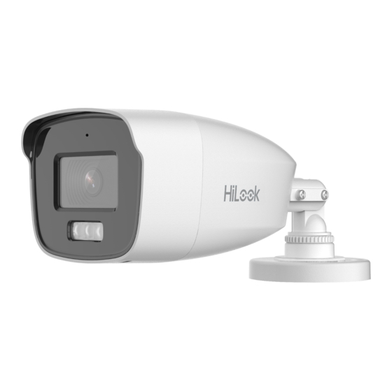
HiLook Series Dual-Light Bullet
User Manual
Thank you for purchasing our product. If there are any
questions, or requests, do not hesitate to contact the
dealer.
This manual applies to the models below:
Type
Type I Camera
Type II Camera
Type III
Camera
Type IV
Camera
Type V
Camera
This manual may contain several technical mistakes or
printing errors, and the content is subject to change
without notice. The updates will be added to the new
version of this manual. We will readily improve or
& Turret Camera
User Manual
Model
THC-B227-LMS
THC-B257-LMS
THC-B127-LPS
THC-B127-LMS
THC-B157-LPS
THC-B157-LMS
THC-T127-LPS
THC-T157-LPS
THC-T127-LMS
THC-T157-LMS
THC-T227-LMS
THC-T257-LMS
Note
2MP model
3K model
2MP model
3K model
2MP model
3K model
2MP model
3K model
2MP model
3K model
Advertisement
Table of Contents

Subscribe to Our Youtube Channel
Related Manuals for HIKVISION THC-B227-LMS


Summary of Contents for HIKVISION THC-B227-LMS
- Page 1 Thank you for purchasing our product. If there are any questions, or requests, do not hesitate to contact the dealer. This manual applies to the models below: Type Model Note 2MP model THC-B227-LMS Type I Camera 3K model THC-B257-LMS 2MP model THC-B127-LPS THC-B127-LMS Type II Camera...
- Page 2 update the products or procedures described in the manual. 01000020220507...
- Page 3 FOR A PARTICULAR PURPOSE. THE USE OF THE PRODUCT BY YOU IS AT YOUR OWN RISK. IN NO EVENT WILL HIKVISION BE LIABLE TO YOU FOR ANY SPECIAL, CONSEQUENTIAL, INCIDENTAL, OR INDIRECT DAMAGES, INCLUDING, AMONG OTHERS, DAMAGES FOR LOSS OF...
-
Page 4: Regulatory Information
UNSAFE NUCLEAR FUEL-CYCLE, OR IN SUPPORT OF HUMAN RIGHTS ABUSES. IN THE EVENT OF ANY CONFLICTS BETWEEN THIS MANUAL AND THE APPLICABLE LAW, THE LATTER PREVAILS. Regulatory Information FCC Information Please take attention that changes or modification not expressly approved by the party responsible for compliance could void the user’s authority to operate the equipment. - Page 5 Safety Instruction These instructions are intended to ensure that user can use the product correctly to avoid danger or property loss. The precaution measure is divided into “Warnings” and “Cautions”. Warnings: Serious injury or death may occur if any of the warnings are neglected.
-
Page 6: Product Features
Do not aim the camera at the sun or extra bright places. The sensor may be burned out by a laser beam, so when any laser equipment is in using, make sure that the surface of sensor will not be exposed to the laser beam. -
Page 7: Installation
Figure 1-2 Overview of Type II Camera Note: Press and hold the switch button for 5 seconds to switch the video output. Four kinds of video outputs are available: TVI, AHD, CVI, and CVBS. 1.2.3 Overview of Type III Camera Switch Button Base Power Cord... - Page 8 Make sure that the device in the package is in good condition and all the assembly parts are included. Make sure that all the related equipment is power-off during the installation. Check the specification of the products for the ...
- Page 9 3. (Optional) Drill the cable hole, when the cables are routed through the wall. 4. Take apart the junction box. 5. Fix the camera to the junction box cover with three PM4 × 10 screws. Figure 2-3 Fix the Camera to the Junction Box Cover 6.
- Page 10 3. (Optional) For cement ceiling, drill the screw holes with a 5.5 mm drill and insert the supplied wall plugs. 4. (Optional) Drill the cable hole, when the cables are routed through the ceiling. 5. Use two PA4 × 25 screws (supplied) to secure the base to the ceiling.
- Page 11 3. (Optional) For cement ceiling, drill the screw holes with a 5.5 mm drill and insert the supplied wall plugs. 4. (Optional) Drill the cable hole, when the cables are routed through the ceiling. 5. Secure the junction box body on the ceiling with four PA4 ×...
- Page 12 You need to purchase a wall mount in advance. Steps: 1. Drill Ø10 mm screw holes in the wall where you want to install the wall mount. 2. Use four M6 expansion bolts to fix the wall mount onto the wall. Fix the Wall Mount Figure 2-14 3.
- Page 13 i. Method 1: Secure the installation plate to the ceiling with three PA4 × 25 screws (supplied). Method 2: Drill the screw holes with a 5.5 mm drill and insert the supplied wall plugs, and secure the installation plate to the ceiling with three PA3 × 25 screws.
- Page 14 6. Fix the junction box cover to the junction box body. Junction Box Body Junction Box Cover Figure 2-21 Fix Junction Box Cover to Junction Box Body Figure 2-22 Finish Installation 7. Route the cables through the bottom cable hole or the side cable hole of the junction box.
- Page 15 Figure 2-25 Finish Installation Installation of Type V Camera 2.4.1 Ceiling Mounting Steps: 1. Paste the drill template (supplied) to the installation location. 2. (Optional) For cement ceiling, drill the screw holes with a 5.5 mm drill and insert the supplied wall plugs.
- Page 16 2). Move the main body up and down to adjust the tilt position [0° to 75°]. 3). Rotate the main body to adjust the rotation position [0° to 360°]. 2.4.2 Wall Mounting without Junction Box Before you start: You need to purchase a wall mount in advance. Steps: 1.
- Page 17 Figure 2-32 Finish Installation 2.4.3 Wall Mounting with Junction Box Before you start: You need to purchase a junction box in advance. Ceiling mounting with a junction box is similar to ceiling mounting with an inclined ceiling mount. Following steps take a junction box as an example.
-
Page 18: Menu Description
6. Secure the junction box cover to the junction box cover with four PA4 × 25 screws. Refer to step 4 to 6 of 2.4.1 Ceiling Mounting to adjust the angle and finish the installation. Figure 2-35 Finish Installation 3 Menu Description Please follow the steps below to call the menu. -
Page 19: Video Format
VIDEO FORMAT EXPOSURE MODE EXPOSURE BACK EXIT SAVE & EXIT LIGHTING MODE IR/WHITE LIGHT SMART IR THRESHOLD LIGHTING SETTINGS LEVEL BACK EXIT SAVE & EXIT IMAGE MODE WHITE BALANCE BRIGHTNESS CONTRAST VIDEO SHARPNESS SETTINGS SATURATION MAIN MENU BACK EXIT SAVE & EXIT AUDIO VOLUME AUDIO... -
Page 20: White Light
2MP@30fps 4MP@25fps 3K models 4MP@30fps 2MP@25fps 2MP models 2MP@30fps All models CVBS NTSC 3.3 EXPOSURE EXPOSURE MODE You can set the EXPOSURE MODE to GLOBAL, BLC, HLC, or DWDR. GLOBAL GLOBAL refers to the normal exposure mode which adjusts lighting distribution, variations, and non-standard processing. -
Page 21: Video Settings
Set it to OFF to give up this function. AUTO You can set THRESHOLD and LEVEL in this section. THRESHOLD The higher the threshold is, the more sensitive the device is to dark environment. LEVEL You can adjust the maximum brightness of supplement light. -
Page 22: Audio Settings
SHARPNESS Sharpness determines the amount of detail an imaging system can reproduce. SATURATION Saturation is the proportion of pure chromatic color in the total color sensation. Adjust this feature to change the saturation of the color. DNR refers to digital noise reduction. This function reduces noise in video stream.
Need help?
Do you have a question about the THC-B227-LMS and is the answer not in the manual?
Questions and answers