Table of Contents
Advertisement
Quick Links
User Manual
Thank you for purchasing our product. If there are any
questions, or requests, do not hesitate to contact the
dealer.
This manual applies to the models below:
This manual may contain several technical mistakes or
printing errors, and the content is subject to change
without notice. The updates will be added to the new
version of this manual. We will readily improve or
update the products or procedures described in the
manual.
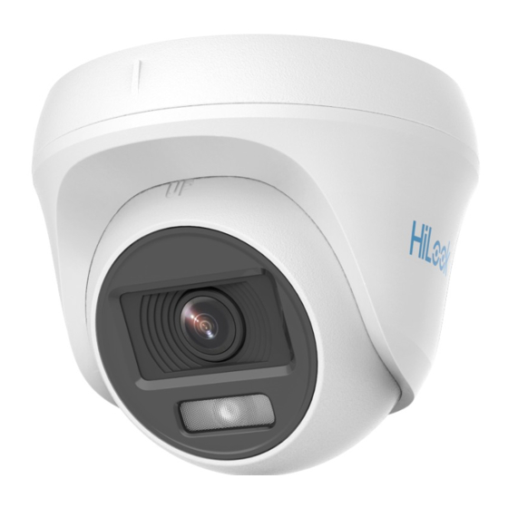
2 MP Turret Camera
Type
Type I
Type II
Type III
HiLook Series
User Manual
Model
THC-T129-P
THC-T129-M
THC-T229-M
0101002000102
Advertisement
Table of Contents

Related Manuals for HIKVISION THC-T129-P


Summary of Contents for HIKVISION THC-T129-P
- Page 1 This manual applies to the models below: Type Model Type I THC-T129-P Type II THC-T129-M Type III THC-T229-M This manual may contain several technical mistakes or printing errors, and the content is subject to change without notice.
-
Page 2: Regulatory Information
Regulatory Information FCC Information Please take attention that changes or modification not expressly approved by the party responsible for compliance could void the user’s authority to operate the equipment. FCC compliance: This equipment has been tested and found to comply with the limits for a Class A digital device, pursuant to part 15 of the FCC Rules. - Page 3 Safety Instruction These instructions are intended to ensure that user can use the product correctly to avoid danger or property loss. The precaution measure is divided into “Warnings” and “Cautions”. Warnings: Serious injury or death may occur if any of the warnings are neglected.
-
Page 4: Product Features
To avoid heat accumulation, good ventilation is required for the operating environment. Keep the camera away from liquid while in use for non-water-proof device. While in delivery, the camera shall be packed in its original packing, or packing of the same texture. Mark Description Table 0-1 Mark Description Mark... -
Page 5: Installation
1.2.3 Overview of Type III Camera Trim Ring Enclosure Main Body Switch Button Power Cord DC 12 V Mounting Video Cable Base Figure 1-3 Overview of Type III Camera Note: Press and hold the switch button for 5 seconds to switch the video output. - Page 6 3. Paste the drill template (supplied) to the place where you want to install the camera. 4. (Optional) For cement ceiling, drill the screw holes with a 5.5 mm drill and insert the supplied wall plugs. Figure 2-3 Drill Template 5.
- Page 7 You need to purchase a junction box in advance. Steps: 1. Loosen screws to take apart the junction box. 2. Paste the drill template for junction box to the place where you want to install the camera. 3. (Optional) For cement ceiling, drill the screw holes with a 5.5 mm drill and insert the supplied wall plugs.
- Page 8 Steps: 1. Drill Φ 10 mm screw holes in the wall where you want to install the wall mount. 2. Use four M6 expansion bolts to fix the wall mount onto the wall. Figure 2-11 Fix the Wall Mount 3. Refer to steps 1 and 2 of 2.1.1 Ceiling Mounting Without Junction Box to dissemble the camera.
- Page 9 Figure 2-15 Dissemble the Camera 9. Secure the mounting base to the ceiling with three PA4 × 25 screws. Figure 2-16 Attach the Gang Box to the Ceiling 10. Pull out the clip plate and install the camera back to the mounting base.
- Page 10 Figure 2-19 Drill Template 3. (Optional) Drill the cable hole, when the cables are routed through the ceiling. 4. Take apart the junction box. 5. Secure the junction box body on the ceiling with PA4 × 25 screws that come with the junction box. Figure 2-20 Secure the Junction Box Body 6.
- Page 11 3. Loosen the screw and pull out the clip plate to dissemble the camera. Figure 2-23 Dissemble the Camera 4. Use three M4 screws to fix the mounting base onto the wall mount. Figure 2-24 Fix the Mounting Base onto the Wall Mount 5.
- Page 12 Figure 2-27 Remove the Trim Ring 5. Secure the camera to the ceiling with three PA4 × 25 screws (supplied). Figure 2-28 Secure the Camera to the Ceiling 6. Connect the power cord and video cable. 7. Loosen the screw and the clip plate. Figure 2-29 Loosen the Screw and Clip Plate 8.
- Page 13 Figure 2-31 Install the Trim Ring Back 11. Turn the trim ring clockwise to secure the camera. Figure 2-32 Secure the Camera 2.3.2 Installation with Junction Box/Inclined Ceiling Mount Before you start: You need to purchase a junction box or inclined ...
- Page 14 Figure 2-35 Fix the Camera onto Junction Box Cover 7. Secure the junction box body on the wall with four PA4 × 25 screws. Figure 2-36 Secure the Junction Box Body 8. Route the cables through the bottom cable hole or the side cable hole of the junction box and connect the cables.
-
Page 15: Menu Description
Figure 2-39 Remove the Trim Ring 4. Install the camera to the wall mount with three PA4 × 25 screws (supplied). Figure 2-40 Install the Camera 5. Refer to steps 6 to 11 of 2.3.1 Ceiling Mounting Without Junction Box to finish installation. 3 Menu Description Please follow the steps below to call the menu. -
Page 16: Video Format
VIDEO FORMAT EXPOSURE MODE ANTI- BANDING EXPOSURE BACK EXIT SAVE & EXIT IMAGE MODE WHITE BALANCE BRIGHTNESS CONTRAST VIDEO SHARPNESS SETTINGS SATURATION 3 DNR MIRROR BACK EXIT SAVE & EXIT MAIN MENU LIGHT SMART THRESHOLD LIGHT LEVEL BACK EXIT SAVE & EXIT ALARM MODE BACK FUNCTIONS... -
Page 17: Video Settings
3.3 EXPOSURE EXPOSURE MODE You can set the EXPOSURE MODE to GLOBAL, BLC, HLC, or DWDR. GLOBAL GLOBAL refers to the normal exposure mode which adjusts lighting distribution, variations, and non-standard processing. BLC (Backlight Compensation) BLC (Backlight Compensation) compensates light to the object in the front to make it clear, but this may cause over-exposure of the background where the light is strong. - Page 18 the image. You can set WHITE BALANCE mode to AUTO or MANUAL. AUTO Under AUTO mode, white balance is being adjusted automatically according to the color temperature of the scene illumination. MANUAL You can adjust the R-GAIN and B-GAIN value to correct colors manually.
-
Page 19: Alarm Mode
SMART LIGHT AUTO LIGHT THRESHOLD LEVEL BACK EXIT SAVE & EXIT Figure 3-5 SMART LIGHT AUTO Under the AUTO mode, the white light turns on automatically as the environment becomes dark. The THRESHOLD is the environmental light level at which the white light turns on.
Need help?
Do you have a question about the THC-T129-P and is the answer not in the manual?
Questions and answers