
Subscribe to Our Youtube Channel
Related Manuals for BERMAD C15


Summary of Contents for BERMAD C15
- Page 1 C15, C35 - Combination Air Valve Installation, Operation and Maintenance Manual (IOM) 2”; DN50 C15 2”; DN50 C35 Updated Jan 2020 Page #1...
- Page 2 Page 3 Operational Data Page 3 Materials and Connections Page 3 C15 / C35 – Parts List Page 4 - 5 Unpacking and post shipment - Inspection, Site Preparation, Installation Page 6 Operation - Start-up and first operation, Operation Principals...
-
Page 3: Operational Data
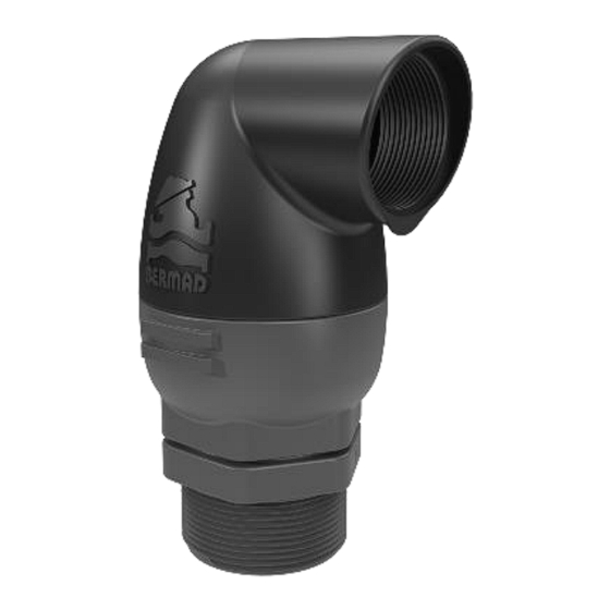
General BERMAD C15/C35 is a high quality combination air valve for a variety of water networks and operating conditions. It evacuates air during pipeline filling, allows efficient release of air pockets from pressurized pipes and enables large volume air intake in the event of network draining. - Page 4 C15 Part List Updated Jan 2020 Page #4...
- Page 5 C35 Part List Updated Jan 2020 Page #5...
-
Page 6: Unpacking And Post Shipment Inspection
The C30 / C31 air valves are not to be used in systems containing high suspended solids; consider selecting other BERMAD Air Valve models for such water type. Installation Typical Applications ... -
Page 7: Operation
Installation instructions • Install the Air Valve as close as possible to the pipe, at a high point of its circumference, in vertical position (within 5 degrees of vertical alignment) and with its inlet facing down. • The diameter of the pipe connecting the Air Valve with the pipeline should be at least equal to the Air Valve inlet diameter. -
Page 8: Maintenance
Valve does not release air or allow air Verify that the operation pressure does not exceed intake the valve's rated working pressure. Check and removed foreign objects, Clean the valve's internal parts, replace if necessary. Consult BERMAD if the symptom continues. Updated Jan 2020 Page #8... - Page 9 Disassembling C15 / C35 1. Release the valve’s cover (Part #2) by turning it counterclockwise, un-screw and remove it from the valve’s base (Part #1). Make sure that the valve parts, seated within the cover do not fall out of the cover.
- Page 10 2. Wet the new peal seal with clean water .Use the Insertion Assistance Handle and insert the peal seal to its designated groove in the kinetic plug as shown in Figure B. Figure B 3. Use the Insertion Assistance Handle and insert the peal seal to its designated groove in the automatic float, insert the "legs"...
- Page 11 3.2 Take the kinetic plug which includes the automatic orifice and O-Ring. Connect the 2 "legs" to the kinetic plug, See Figure G. Figure G 3.3 Insert the "legs" to the 2 holes in the automatic float, See Figure H. Figure H 4.
- Page 12 Figure J 6. Reassemble the valve cover to the valve basis by screwing it on the basis thread. Tighten the cover till the BERMAD logo is parallel with the wrench plats of the basis, See Figure K. Figure K 7. Once the valve is reassembled; perform a complete start up procedure as described above.
Need help?
Do you have a question about the C15 and is the answer not in the manual?
Questions and answers