
Subscribe to Our Youtube Channel
Related Manuals for BERMAD C80


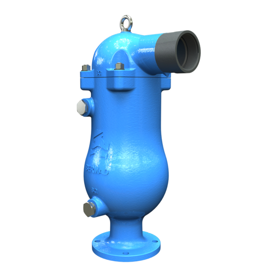
Summary of Contents for BERMAD C80
- Page 1 NON-CLEAN, SEWAGE & WASTEWATER COMBINATION AIR VALVE Model C80 Installation, Operation & Maintenance Manual (IOM)
-
Page 2: Table Of Contents
Pre-Installation Requisites ..............................6 Post Shipment ................................6 Site Preparation ................................6 Installation Instructions ..............................7 Adding Additional Feature to the C80 Air Valve ....................... 9 First startup ..................................10 Operation and Monitoring .............................. 11 Quick maintenance ................................. 12 Periodic maintenance ..............................14 Troubleshooting ................................ - Page 3 Table of Figures Figure 1 - Installation options ............................8 Figure 2 – SP Picture ................................. 9 Figure 3 - AC Picture ................................9 Figure 4 - IP Picture ................................. 10 Figure 5 - Quick flush ..............................13 Figure 6 - Periodic maintenance A ..........................14 Figure 7- Periodic maintenance B ...........................
-
Page 4: Introduction
Sewage & Wastewater networks and operating conditions. The C80 evacuates air during pipeline filling, allows efficient release of air and gas pockets from pressurized pipes, and enables large volume air intake in the event of network draining. The elongated body and lower float prevent the fluid to be in contact with the upper mechanism. -
Page 5: Maintenance
Maintenance Prior to any maintenance work to be done on the air valve make sure that: ▪ Before any maintenance or non-regular operation, close the Isolation / ball valve, which is installed below the air valve. ▪ Comply with and follow all the standards and regulations for handling the fluids on which the air valve is operated. -
Page 6: Pre-Installation Requisites
Pre-Installation Requisites Post Shipment Make sure that till the actual installation the valve remains dry and clean in its original package. ▪ Unpack the valve and make sure that all the wrapping materials are removed. ▪ Before installation it is necessary to inspect that no damage to the valve had occurred during shipment;... -
Page 7: Installation Instructions
Smaller diameter will decrease the air flow capacity of the air valve. (Please refer to Bremad’s “Air- The following pictures depict some typical installations of the C80 air valve Control - WW-Engineer Guide_v13.pdf” document):... -
Page 8: Figure 1 - Installation Options
Figure 1 - Installation options... -
Page 9: Adding Additional Feature To The C80 Air Valve
Adding Additional Feature to the C80 Air Valve Surge Protection Device: Please refer to the following picture for adding a Surge protection device to the C80 Air Valve: Figure 2 – SP Picture Assisted Closing Device: Please refer to the following picture for adding an Assisted Closing device to the C80 Air Valve:... -
Page 10: First Startup
Inflow Prevention Device: Please refer to the following picture for adding an Inflow Prevention device to the C80 Air Valve: Figure 4 - IP Picture First startup ▪ Open the Isolation / ball valve and verify that the air valve connections are not leaking; if needed follow the troubleshooting instruction section of this document. -
Page 11: Operation And Monitoring
Operation and Monitoring Principles of operation Pipeline filling During the filling process of a pipeline, high air flow is forced out through the kinetic orifice of the air valve. Once water enters the valve’s chamber, the float buoyed upwards causes the kinetic orifice to close. -
Page 12: Quick Maintenance
Quick maintenance The C80 air valve’s body has two service ports (upper and lower) that allow the user, when needed and depend on the dirt-load, to perform a quick flushing of the valve’s internal body (See the following picture): 1. -
Page 13: Figure 5 - Quick Flush
Pressurized clean water Proper drainage line Figure 5 - Quick flush... -
Page 14: Periodic Maintenance
Periodic maintenance A periodical inspection of the seals and flushing of the valve are recommended for removing debris, foreign objects, and grease that might interfered with the regular operation of the air valve. The valve’s flushing and cleaning frequency depends on sewage and wastewater characteristics and dirt- load. -
Page 15: Figure 7- Periodic Maintenance B
• Pull out the internal assembly of the air valve. Figure 7- Periodic maintenance B • Using 3/32” Allen key, disconnect the locking screw of the automatic mechanism, and separate the upper float assembly from the rest of the internal mechanism. Figure 8 - Periodic maintenance C... -
Page 16: Figure 9 - Periodic Maintenance D
• Remove any foreign objects • Flush and clean the automatic orifice seals Figure 9 - Periodic maintenance D • Flush and clean the kinetic orifice and its seal. Figure 10 - Periodic maintenance E • Check for signs of wear and tear or any damaged parts. -
Page 17: Figure 11 - Replacing The Seals - A
• If needed replace the automatic seal and the kinetic seal. • Replace the automatic seal: Remove the old seal [A], insert one side of the new seal to its designated slot [C], insert the other side of the seal to the opposite side slot, and cut the excessive rubber rods [D]. -
Page 18: Figure 13 - Replacing The Seals - C
• Pull out the seal assembly [A] and replace the seal [B]. Figure - Replacing the seals - C • Reassemble the air valve in reverse order. • Tighten the four side cover bolts to 25 N-m torque. • Reopen the isolation valve. If during the periodic maintenance procedure, signs of wear and tear are found on the air valve components, please refer to the Disassembling the air valve chapter of this document. -
Page 19: Troubleshooting
Check and remove foreign objects. Clean the valve’s internal parts, replace if necessary. Consult Bermad if the symptom continues. Disassembling the air valve Perform the following stages when a complete disassembly of the air valve is required: 1. -
Page 20: Figure 14 - Disassembling The Air Valve - A
3. Slowly open the drainage valve, or the ball valve, located on the lower side of the air valve body, make sure that the pressure is released; take extra care while releasing the hazardous, high energy, compressed gas. 4. Make sure that the air valve is completely empty from liquids before starting the maintenance process. -
Page 21: Figure 15 - Disassembling The Air Valve - B
6. Disassemble the lower float from the automatic subassembly by unscrewing the screw. Unscrew and disconnect the float from the lower float rod. Figure 15 - Disassembling the air valve - B Replacing the seals 1. Disassemble the roll seal; remove the automatic subassembly housing and disassemble the roll seal seating nut. -
Page 22: Figure 17 - Replacing The Seals - B
2. Disassemble the spring by unscrewing the locking nut of the spring assembly. Figure 17 - Replacing the seals - B 3. Disassemble the automatic orifice seat by unscrewing the locking bolt of the orifice seat. Figure 18- Replacing the seals - B... -
Page 23: Figure 19 - Replacing The Seals - C
4. Disassemble the automatic orifice by pulling out the orifice assembly from its seat. Figure 19 - Replacing the seals - C 5. Disassemble the kinetic seal assembly by unscrewing the 4 bolts and removing the locking ring. Figure 20 - Replacing the seals - D... -
Page 24: Figure 21 - Replacing The Seals - E
6. Remove the kinetic sealing subassembly from the side cover. Figure 21 - Replacing the seals - E 7. Disassemble the Spring subassembly. Important note: The Cover subassembly of the C80 Air Valve has two versions, Earlier [A] and Later [B]: Version A Version B Figure 22 - Versions... -
Page 25: Figure 23 - Version A
Therefore, disassembling the spring assembly is different in version A from version B Please refer to the BOM drawings ahapter of this document: Version A [Earlier] disassembly Figure 23 - Version A Version B [Later] disassembly Figure 24 - Version B... -
Page 26: Reassembly And Returning To Service
Reassembly and returning to service Reassemble the air valve in reverse order. 1. Reassemble the spring subassembly, Version A [Earlier]. Apply Loctite on the threads before screwing and screw the Nut with M6 Key by hand force only. Figure 25 - Reassembling - A Reassemble the spring subassembly, Version B [Later]. -
Page 27: Figure 27 - Reassembling - C
2. Install the kinetic sealing subassembly to the cover. Figure 27 - Reassembling - C 3. Reinstall the locking ring. Apply Loctite on the threads before screwing and screw the Nut with M6 Key by hand force only. Figure 28 - Reassembling - D 4. -
Page 28: Figure 30 - Reassembling - F
5. Using 3/16” Allen key, screw the locking bolt of the automatic orifice seat. Figure 30 - Reassembling - F 6. Reconnect the lower float to the automatic subassembly with the locking screw. Use 2mm Allen Key. Apply Loctite on the threads. Figure 31 - Reassembling - G... -
Page 29: Figure 32 - Reassembling - H
7. Using 3/16” Allen Key, connect the upper float assembly by tightening the locking screw. Figure 32 - Reassembling - H 8. Return the cover O-ring, if removed. 9. Insert the internal assembly into the valve body Figure 33 - Reassembling - I... -
Page 30: Figure 34 - Reassembling - J
10. Using Key number 22, tighten cover nuts with 25Nm force. Figure 34 - Reassembling - J 11. Slowly reopen the isolation / ball valve 12. Monitor the air valve's closure... -
Page 31: Bom Drawings And Tables
BOM Drawings and tables Version A Figure 35 - BOM Version A... -
Page 32: Figure 36 - Bom Version B
Version B Figure 36 - BOM Version B... -
Page 33: Spare Parts List
Spare parts list... - Page 34 ITEM ITEM CODER DESCRIPTION NUMBER 8230040060-KIT ELASTOMER KIT 8230080092 3" + 4" (C80), LOWER FLOAT ASSEMBLY SEAL ASSY. FOR SEWAGE –VERSION B 8230080093 3"-4" (C80), GREY PP PEAL SEAL ASSY. FOR SEWAGE – VERSION A 8230080094 3"-4" (C80), GREY PP...
-
Page 35: Bermad Standard International Limited Warranty
Bermad Standard International Limited Warranty BERMAD C S LTD. (“BERMAD”) w a r r a n t s that, for a period of 12 months from the day of delivery of the product by BERMAD to its customer (the “Warranty Period”), each component of the product shall be free from defects in material or workmanship and shall meet, in all material respects, the products technical specifications as defined by BERMAD. -
Page 36: Iom Bermad Disclaimer
The information contained in this IOM should be used only by professional water systems engineers and technicians, who can fully understand it and the risks involved therewith. Although BERMAD has made every effort to ensure that this IOM is accurate; BERMAD disclaims liability for any inaccuracies or omissions that may have occurred.
Need help?
Do you have a question about the C80 and is the answer not in the manual?
Questions and answers