
Related Manuals for BERMAD 400E-Y


Summary of Contents for BERMAD 400E-Y
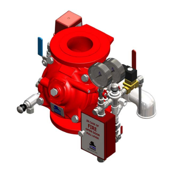
- Page 1 400E-Y Deluge Valve Bermad 400E-Y Torrent Deluge Valve Installation Operation Maintenance Manual (IOM)
- Page 2 When performing a procedure, follow the steps in succession without omission. General The BERMAD 400E-Y Water Control Valve designed for vertical or horizontal installation and is used for Deluge, Pressure Control Deluge and Pre-action in Firewater or Foam systems.
- Page 3 ■ Proper operation of the Bermad 400E-Y Deluge Valves depends upon their trim being installed. ■ The 400E-Y valve shall be trimmed with specific trim components and accessories, it must be installed and maintained in compliance with the most recent Bermad publications.
-
Page 4: B Priming Strainer 1/2
3. Operation 3.1 Hydraulically Controlled Bermad Hydraulically Controlled Deluge valve is suitable for automatic or remote controlled water or foam systems that include a wet pilot-line with closed fusible plugs (thermal releases) and piping systems .The typical wet pilot- line is installed in a covered area and connected to the valve trim. In fire conditions, operation of a release device on the wet pilot line opens the Deluge Valve, allowing water to enter the system piping. - Page 5 Water Motor Alarm provided in the Trim package. These items must be obtained from Bermad or an outside supplier prior to installation package of the deluge valve and trim. (9) Manual Emergency Release may be Model B (open Bracket)
- Page 6 Water Motor Alarm provided in the Trim package. These items must be obtained from Bermad or an outside supplier prior to installation package of the deluge valve and trim. (9) Manual Emergency Release may be Model B (open...
- Page 7 URV-MA Manual Reset & Adjustable the Trim package. These items must be obtained from Bermad or an outside supplier prior to installation package of the deluge Optional System Items: ...
-
Page 8: E-Y Deluge Valve 1
Valve Visual Position Indicator provided in the Trim package. These items must be obtained Valve Limit Switch from Bermad or an outside supplier prior to installation Water Motor Alarm package of the deluge valve and trim. -
Page 9: F Fittings And Tubing
Valve Visual Position Indicator provided in the Trim package. These items must be obtained Valve Limit Switch from Bermad or an outside supplier prior to installation Water Motor Alarm package of the deluge valve and trim. -
Page 10: Shall Be Ul Listed In Accordance With Ul
Optional System Items: provided in the Trim package. These items must be obtained from Bermad or an outside supplier prior to installation Pressure Switch package of the deluge valve and trim. Valve Visual Position Indicator... -
Page 11: A Alarm Test Valve 1/2" 1
Solenoid Valve and requires a Listed/Approved control panel with a compatible electrical fire detection system. In Fire conditions, activation of the detection system causes the System Control Panel to be activated. This in turn opens the Solenoid Valve, causing the Bermad Deluge Valve to open, and thereby allowing water to enter the system piping. -
Page 12: P Pressure Switch
Trim package. These items must be obtained Valve Limit Switch from Bermad or an outside supplier prior to installation Water Motor Alarm package of the deluge valve and trim. -
Page 13: P Pressure Switch
Optional System Items: provided in the Trim package. These items must be obtained Pressure Switch from Bermad or an outside supplier prior to installation Valve Visual Position Indicator package of the deluge valve and trim. -
Page 14: P Pressure Switch
Pressure Switch provided in the Trim package. These items must be obtained from Bermad or an outside supplier prior to installation Valve Visual Position Indicator package of the deluge valve and trim. -
Page 15: P Pressure Switch
Valve Visual Position Indicator provided in the Trim package. These items must be obtained Valve Limit Switch from Bermad or an outside supplier prior to installation Water Motor Alarm package of the deluge valve and trim. -
Page 16: P Pressure Switch
Water Motor Alarm provided in the Trim package. These items must be obtained from Bermad or an outside supplier prior to installation package of the deluge valve and trim. -
Page 17: P Pressure Switch
Valve Visual Position Indicator provided in the Trim package. These items must be obtained Valve Limit Switch from Bermad or an outside supplier prior to installation Water Motor Alarm package of the deluge valve and trim. -
Page 18: P Pressure Switch
Pressure Switch provided in the Trim package. These items must be obtained Valve Visual Position Indicator from Bermad or an outside supplier prior to installation package of the deluge valve and trim. Valve Limit Switch... -
Page 19: P Pressure Switch
400E-Y Deluge Valve Pneumatically Controlled System BERMAD Pneumatically Controlled Deluge Valve is suitable for systems that include dry pilot lines with closed pneumatic fusible plugs and piping systems with a wide variety of open nozzles. In SET position, the water pressure supplied to the deluge valve control chamber is trapped by a closed Pneumatic Pilot Valve and holds the main valve’s diaphragm and plug against the valve seat, sealing it drip-tight and keeping the system piping dry. -
Page 20: P Pressure Switch
Valve Limit Switch provided in the Trim package. These items must be obtained Water Motor Alarm from Bermad or an outside supplier prior to installation Manual Reset (URV-M) package of the deluge valve and trim. -
Page 21: P Pressure Switch
Valve Limit Switch provided in the Trim package. These items must be obtained Water Motor Alarm from Bermad or an outside supplier prior to installation Manual Reset (URV-M) package of the deluge valve and trim. -
Page 22: P Pressure Switch
Trim package. These items must be obtained Local Reset (URV-M) from Bermad or an outside supplier prior to installation package of the deluge valve and trim. -
Page 23: P Pressure Switch
Pneumatic Release and Electric Detection and are controlled either Electrically or through a Dry Pilot Line. The Bermad Deluge Valve is operated by a solenoid valve and a pneumatic pilot valve. The pneumatic pilot valve is normally held closed by the air pressure maintained through a 3-way solenoid valve. In FIRE condition response of... -
Page 24: P Pressure Switch
Manual Reset (URV-M) proper installation and use of the deluge valve and are not provided in the Trim package. These items must be obtained from Bermad or an outside supplier prior to installation package of the deluge valve and trim. -
Page 25: P Pressure Switch
Trim package. These items must be obtained Water Motor Alarm from Bermad or an outside supplier prior to installation Manual Reset (URV-M) package of the deluge valve and trim. -
Page 26: P Pressure Switch
Valve Limit Switch provided in the Trim package. These items must be obtained Water Motor Alarm from Bermad or an outside supplier prior to installation Manual Reset (URV-H) package of the deluge valve and trim. - Page 27 400E-Y Deluge Valve 4. Placing in Service/Resetting The deluge valve and the control trim shall be placed in Service in accordance to the instructions below. After all relevant instructions are performed, slowly open the supply-isolating valve and check that no water flows into the system.
- Page 28 400E-Y Deluge Valve 5. Maintenance Bermad Deluge Valves require no lubrication, packing or tightening and require minimum maintenance WARNING: Do not turn off the water supply to make repairs without placing a roving fire patrol in the area covered by the system. The patrol should continue until the system is back in service.
- Page 29 Where difficulty in performance is experienced, the manufacturer or his authorized representative should be contacted if any field adjustment is to be made. bermadfire@bermad.com • www.bermad.com The information herein is subject to change without notice. BERMAD shall not be held liable for any errors. All rights reserved. © Copyright by BERMAD.
- Page 30 400E-DP-Y 400E-DP-Y Torrent Dry-Pipe Valve Installation Operation Maintenance Manual (IOM)
- Page 31 400E-DP-Y Safety First BERMAD believes that the safety of personnel working with and around our equipment is the most important consideration. Please read all safety information below and any other relevant source before attempting to perform any maintenance function. Comply with all approved and established precautions for working with your type of equipment and/or environment.
- Page 32 2.1.9 Install the necessary accessories, which appear in the drawing. 2.1.10 All additional accessories, although not packed together with the BERMAD Dry Pipe valve, must be installed as shown in the relevant drawing and other illustrations. 2.1.11 Install additional accessories that are required by the NFPA codes or by authorities having jurisdiction.
- Page 33 3. Operations The Bermad Dry-Pipe Control Valve is best suited for automatic dry sprinkler systems. Dry-Pipe Valves are defined as systems that admit water to sprinkler piping only upon operation of automatic sprinkler and/or pneumatic pressure drop in the system-piping network.
- Page 34 400E-DP-Y 3.1.1 Model 400E-DP trim illustration: Dry-Pipe Valve...
-
Page 35: I Valve Visual Position Indicator
400E-DP-Y Model 400E-DP Components List Item Description Note 400E-Y Water Control Valve Alarm Test Valve 1/2" Gauge Valve 1/4" Restriction Orifice Pressure Gauge 4" Priming Strainer 1/2" Drain Valve Priming Check valve 1/2" Alarm Shutoff Valve 1/2" Manual Emergency Release Priming Valve - 1/2"... - Page 36 CLOSED with no leaking 5. Maintenance Bermad Dry Pipe Valve requires no lubrication, packing or tightening and requires minimum maintenance. WARNING: Do not turn off the water supply to make repairs without placing a roving fire patrol in the area covered by the system.
- Page 37 Where difficulty in performance is experienced, the manufacturer or his authorized representative should be contacted if any field adjustment is to be made. bermadfire@bermad.com • www.bermad.com The information herein is subject to change without notice. BERMAD shall not be held liable for any errors. All rights reserved. © Copyright by BERMAD.
- Page 38 400E-Y Pre-Action 400E-Y Torrent Pre-Action Systems Installation Operation Maintenance Manual (IOM)
- Page 39 400E-Y Pre-Action Safety First BERMAD believes that the safety of personnel working with and around our equipment is the most important consideration. Please read all safety information below and any other relevant source before attempting to perform any maintenance function. Comply with all approved and established precautions for working with your type of equipment and/or environment.
- Page 40 Install also the additional accessories, which appear in the drawing and which must be installed as shown in the drawing, although they are not packed together with the Bermad Valve itself. After installation in the main line, carefully inspect/correct any damaged accessories, piping, tubing, or fittings;...
- Page 41 WARNING: whenever either the Solenoid or the Manual Emergency Release is activated, the EMR locks the Bermad Water Control Valve in its open position. The Bermad Water Control Valve will close again only when the reset button on the EMR is pressed wile solenoid is de-energized.
- Page 42 400E-Y Pre-Action Model 400E-7BM, Double Interlock Pre-action System, Electric/Pneumatic-Electric Release, Trim Illustration:...
- Page 43 400E-Y Pre-Action 3.1.1 Model 400E-7BM, Double Interlock Pre-Action System, Electric/Pneumatic-Electric Release, Components List: Item Description Note 400E - Y Water Control Valve 1, 2 Alarm Test Valve 1/2" Gauge Valve 1/4" Pressure Gauge 4" Priming Strainer 1/2" Drain Valve 3, 4...
- Page 44 M pilot valve and requires a listed and approved control panel with a compatible electrical fire detection system. The Bermad 400E-7DM will rest only when the reset handle on the URV-M is pulled wile solenoid is de-energized. WARNING: Whenever the Manual Emergency Release is activated, the Bermad Water Control Valve...
- Page 45 400E-Y Pre-Action Model 7DM, Double Interlock Pre-Action System, 3.2.1 Electric-Pneumatic Release, Trim Illustration:...
- Page 46 400E-Y Pre-Action 3.2.2 Model 7DM, Double Interlock Pre-Action System, Electric-Pneumatic Release, Components List: Item Description Note 400E - Y Type Water Control Valve 1, 2 Alarm Test Valve 1/2" Gauge Valve 1/4" Pressure Gauge 4" Priming Strainer 1/2" Drain Valve...
- Page 47 CLOSED with no leaking 5. Maintenance Bermad Pre Action Valve requires no lubrication, packing or tightening and require minimum maintenance WARNING: Do not turn off the water supply to make repairs without placing a roving fire patrol in the area covered by the system.
- Page 48 Shut off the main supply-isolating valve. Close the pneumatic pressure supply to the system. Close the priming line valve to the Bermad valve control chamber. Open all drain valves to drain all the water from the system . Release the water pressure from the control chamber of the water control valve by pulling the manual emergency release.
- Page 49 Where difficulty in performance is experienced, the manufacturer or his authorized representative should be contacted if any field adjustment is to be made. bermadfire@bermad.com • www.bermad.com The information herein is subject to change without notice. BERMAD shall not be held liable for any errors. All rights reserved. © Copyright by BERMAD.
- Page 50 ● www.bermad.com PAGE 1 OF 1 The information contained in this document is subject to change without notice. BERMAD shall not be liable for any errors contained herein. All Rights Reserved. © Copyright by BERMAD Control Valves. 22.02. 12...
- Page 51 ● www.bermad.com PAGE 2 OF 1 The information contained in this document is subject to change without notice. BERMAD shall not be liable for any errors contained herein. All Rights Reserved. © Copyright by BERMAD Control Valves. 22.02. 12...
- Page 52 ● www.bermad.com PAGE 3 OF 1 The information contained in this document is subject to change without notice. BERMAD shall not be liable for any errors contained herein. All Rights Reserved. © Copyright by BERMAD Control Valves. 22.02. 12...
- Page 53 ● www.bermad.com PAGE 4 OF 1 The information contained in this document is subject to change without notice. BERMAD shall not be liable for any errors contained herein. All Rights Reserved. © Copyright by BERMAD Control Valves. 22.02. 12...
- Page 54 ● www.bermad.com PAGE 5 OF 1 The information contained in this document is subject to change without notice. BERMAD shall not be liable for any errors contained herein. All Rights Reserved. © Copyright by BERMAD Control Valves. 22.02. 12...
- Page 55 ● www.bermad.com PAGE 6 OF 1 The information contained in this document is subject to change without notice. BERMAD shall not be liable for any errors contained herein. All Rights Reserved. © Copyright by BERMAD Control Valves. 22.02. 12...
- Page 56 ● www.bermad.com PAGE 7 OF 1 The information contained in this document is subject to change without notice. BERMAD shall not be liable for any errors contained herein. All Rights Reserved. © Copyright by BERMAD Control Valves. 22.02. 12...
- Page 57 ● www.bermad.com PAGE 8 OF 1 The information contained in this document is subject to change without notice. BERMAD shall not be liable for any errors contained herein. All Rights Reserved. © Copyright by BERMAD Control Valves. 22.02. 12...
- Page 58 ● www.bermad.com PAGE 9 OF 1 The information contained in this document is subject to change without notice. BERMAD shall not be liable for any errors contained herein. All Rights Reserved. © Copyright by BERMAD Control Valves. 22.02. 12...
- Page 59 ● www.bermad.com PAGE 10 OF 1 The information contained in this document is subject to change without notice. BERMAD shall not be liable for any errors contained herein. All Rights Reserved. © Copyright by BERMAD Control Valves. 22.02. 12...
- Page 60 ● www.bermad.com PAGE 11 OF 1 The information contained in this document is subject to change without notice. BERMAD shall not be liable for any errors contained herein. All Rights Reserved. © Copyright by BERMAD Control Valves. 22.02. 12...
- Page 61 ● www.bermad.com PAGE 12 OF 1 The information contained in this document is subject to change without notice. BERMAD shall not be liable for any errors contained herein. All Rights Reserved. © Copyright by BERMAD Control Valves. 22.02. 12...
- Page 62 Model: 43T Pressure Relief Valve Model Bermad Pressure Relief Valve Installation Operation Maintenance Manual (IOM) PAGE 1 OF 10...
- Page 63 Model: 43T Pressure Relief Valve Safety First BERMAD believes that the safety of personnel working with and around our equipment is the most important consideration. Please read all safety information below and from any other relevant source before attempting to perform any maintenance function.
- Page 64 Approvals The Bermad 43T Pressure Relief Valve is UL Listed and FM Approved when. Refer to the current UL and/or FM fire protection equipment directory. Consult Bermad for any component approval recently to appear in any equipment directory.
- Page 65 Model: 43T Pressure Relief Valve Figure 1: Installation Drawing Operation The Pressure-Relief Pilot Valve (#1, fig.2) senses inlet pressure and modulates the control chamber causing the main valve to throttle, thus sustaining constant inlet pressure. When the inlet pressure rises above the setting, the pilot valve opens pressure in the control-chamber decreases and the main valve modulates open to relieve inlet pressure and sustain pilot valve setting.
- Page 66 Model: 43T Pressure Relief Valve Figure 2B: Operation Drawing for Size 8 and 10" Starting –up 4.1 Provide pump shut-off pressure to the 43T Pressure-Relief Valve inlet, allow no system demand. 4.2 Create sufficient pressure (higher than the valve set pressure) to allow flow through the relief valve. 4.3 While relief valve is operating, wait for the valve inlet pressure to stabilize.
- Page 67 Model: 43T Pressure Relief Valve 4.9 Valve size 8" and 10" are equipped with adjustable needle valve to allow presetting of the valve closing speed. By turning the needle valve screw (#5, fig.2B) on the pilot valve bottom, adjust the valve response.
- Page 68 Note Large Capacity Filter where the filter screen frequently becomes blocked In cases where the filter screen frequently becomes blocked, it is recommend replacing the standard filter with BERMAD’s Large Filter Mark “F” (see paragraph 1.2.3). PAGE 7 OF 10...
- Page 69 Model: 43T Pressure Relief Valve 10 General Arrangement (GA) & Outline Dimension Drawings Figure 3A: GA Drawing for Size 3 - 6" PAGE 8 OF 10...
- Page 70 Model: 43T Pressure Relief Valve Figure 3B: GA Drawing for Size 8 - 10" PAGE 9 OF 10...
- Page 71 KEEP THIS PAGE BLANK appliceng@bermad.com ● www.bermad.com The information contained in this document is subject to change without notice. BERMAD shall not be liable for any errors contained herein. All Rights Reserved. © Copyright by BERMAD Control Valves. Rev. 22.02.12...
Need help?
Do you have a question about the 400E-Y and is the answer not in the manual?
Questions and answers