
Related Manuals for BERMAD C10


Summary of Contents for BERMAD C10
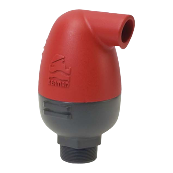
- Page 1 Combination Air Valve Model Model C10 /C11 Installation, Operation and Maintenance Manual (IOM)
-
Page 3: Table Of Contents
Maintenance ............Page 14 Troubleshooting ............Page 15 Disassembling C10 / C11 (sizes ¾-1" / DN25 DN50) ...Page 16 Reassembling C10 / C11 (sizes ¾-1" / DN25 DN50)..Page 17 Disassembling C10 / C11 (size 2" / DN50) ....Page 20... -
Page 4: General
General The BERMAD C10 / C11 is a high quality combination Air Valve for a variety of water networks and operating conditions. It evacuates air during pipeline filling, allows efficient release of air pockets from pressurized pipes, and enables large volume air intake in the event of network draining. -
Page 5: Operational Data
Body material Glass-reinforced Nylon Inlet diameter ¾", 1", 2" DN20, DN25, DN50 Connections Threaded Male BSPT / NPT Outlet types Sideways, Downwards (DN50 / 2" only) Additional features (2" / DN50 only): Surge Protection (C10-SP, C11-SP) Inflow Prevention (C10-IP, C11-IP) -
Page 6: C10 Parts List (¾"-1" / Dn20 - Dn25)
C10 Parts List C10 Parts List ¾"-1" / DN20 - DN25 Body (#2) Kinetic Seal (#4) Seals Kit (#60) Kinetic Plug (#6) Peal Seal (#5) Kinetic Plug Legs (#33) Kinetic Plug + Legs Kit (#40) Float (#3) O-Ring (#5011) Base (#1) -
Page 7: C10 Parts List 2" / Dn50
C10 Parts List 2" / DN50 Body (#2) Drain Elbow (#8) Kinetic Seal (#4) Seals Kit (#60) Peal Seal (#5) Kinetic Plug (#6) Float (#3) O-Ring (#5012) Base (#1) -
Page 8: C11 Parts List ¾"-1" / Dn20 - Dn25
C11 Parts List ¾"-1" / DN20 - DN25 Body (#2) Kinetic Seal (#4) Kinetic Plug + Kinetic Plug (#6) Auto Orifice + Legs Kit (#40) Kinetic Plug Leg (#33) O-Ring (Auto Orifice #5000) Auto Orifice (#14) Auto Orifice Seal (#18) Seals Kit (#60) Float (#3) O-Ring (Base #5012) -
Page 9: C11 Parts List 2" / Dn50
C11 Parts List 2" / DN50 Body (#2) Drain Elbow (#8) Kinetic Seal (#4) Kinetic Plug + Kinetic Plug (#6) Auto Orifice + Legs Kit (#40) O-Ring (Auto Orifice #5000) Auto Orifice (#14) Seals Kit (#60) Auto Orifice Seal (#18) Float (#3) O-Ring (Base #5011) Base (#1) -
Page 10: Surge Protection (Sp) - Parts List
Surge Protection (SP) – Parts List Surge Seal (#11) Grid (#10) Surge Extension (#9) Drain Elbow (#8) -
Page 11: Inflow Prevention (Ip) - Parts List
Inflow Prevention (IP) – Parts List O-Ring (#5074) Grid (#10) Inflow Seal (#11) Surge Extension (#9) Drain Elbow (#8) -
Page 12: Unpacking And Post Shipment Inspection
ƒ The C10 / C11 Air Valves are not to be used in systems containing high suspended solids; consider selecting other BERMAD Air Valve models... -
Page 13: Installation
Installation Typical Applications ƒ Main Irrigation Networks – Air relief, protection against air accumulation and vacuum formation downstream of pumps, along supply lines and at elevations in main irrigation networks. ƒ Irrigation Control Heads – Air relief, protection against air accumulation and vacuum formation in filtration and fertilization stations and downstream of main control valves. -
Page 14: Operation
Installation instructions ƒ Install the Air Valve as close as possible to the pipe, at a high point of its circumference, in vertical position (within 5 degrees of vertical alignment) and with its inlet facing down. ƒ The diameter of the pipe connecting the Air Valve with the pipeline should be at least equal to the Air Valve inlet diameter. -
Page 15: Principles Of Operation
Principles of Operation Pipeline Filling During the filling process of a pipeline, high air flow is forced out through the kinetic orifice of the Air Valve. Once water enters the valve’s chamber, the float buoyed upward causes the kinetic orifice to close. The unique aerodynamic structure of the valve body and float ensures that the float cannot be closed before water reaches the valve. -
Page 16: Maintenance
Surge Protection (Anti-slam) The anti-slam device (SP) is fitted to the Air Valve outlet. In the event of pressure surge, it partially closes the valve's outlet. The approaching water column decelerates due to the resistance of the rising air pressure in the valve. Inflow Prevention The inflow prevention (IP) is a Normally Closed check device fitted on the valve's outlet and preventing flow... -
Page 17: Troubleshooting
Valve does Verify that the operation pressure does not release air not exceed the valve's rated working or allow air intake pressure. Check and removed foreign objects, Clean the valve's internal parts, replace if necessary. Consult BERMAD if the symptom continues. -
Page 18: Disassembling C10 / C11 (Sizes ¾-1" / Dn25 Dn50)
Disassembling C10 / C11 (sizes ¾ - 1" / DN25 DN50) 1. Release the valve’s cover (Part #2) by turning it counterclockwise, un-screw and remove it from the valve’s base (Part #1). Make sure that the valve parts, seated within the cover do not fall out of the cover. -
Page 19: Reassembling C10 / C11 (Sizes ¾-1" / Dn25 Dn50)
Fig. A (C10) Fig. A (C11) upward. See figure A. 2. For C10 (sizes ¾ - 1" / DN20 DN25). a. Wet the new peal seal (Part #5) with clean water. Use the Insertion Assistance Handle and insert the peal seal (Part #5) to its designated Fig. - Page 20 3. For C11 (sizes ¾- 1" / DN20 DN25) a. Insert the Orifice seal (Part #18) to its groove on the float (Part #3), See Figure E. b. Take the kinetic plug (part Fig. E #4), which includes the automatic orifice (Part #14) and O-Ring (part #5000).
- Page 21 6. Reassemble the valve cover to the valve basis by screwing it on the basis thread. Tighten the cover until the BERMAD logo is parallel with the wrench plates of the basis, See Figure K. 7. Reassemble the valve and perform a complete start up procedure as Fig.
-
Page 22: Disassembling C10 / C11 (Size 2" / Dn50)
Disassembling C10 / C11 (size 2" / DN50) 1. Release the valve’s cover (Part #2) by turning it counterclockwise, un-screw and remove it from the valve’s base (Part #1). Make sure that the valve parts, seated within the cover do not fall out of the cover. -
Page 23: Reassembling C10 / C11 (Size 2" / Dn50)
Reassembling C10 / C11 (size 2" / DN50) 1. Wet the Kinetic Seal (Part #4) with water and install it on the Kinetic Plug (Part #6) with its raised edges side facing upward. See figure A. Fig. A (C10) Fig. A (C11) 2. - Page 24 See Figure E. 4. Connect the Kinetic Plug (Part #6) to the float (Part #3) using its Snap Fig. F (C10) Fig. F (C11) legs in the right orientation as shown in. See Figure F. 5. Make sure that the valve’s...
- Page 25 7. Reassemble the valve cover to the valve basis by screwing it on the basis thread. Tighten the cover until the BERMAD logo is parallel with the wrench plats of the basis. See Figure I. 8. Reassemble the valve and perform a complete start up procedure Fig.
- Page 28 www.bermad.com...
Need help?
Do you have a question about the C10 and is the answer not in the manual?
Questions and answers