
Related Manuals for SPX APV DELTA MS4


Summary of Contents for SPX APV DELTA MS4
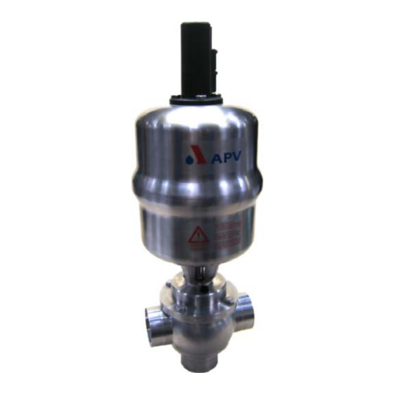
- Page 1 Operating Manual D E L T A M S 4 Diaphragm Valve with fan support Read and understand this manual prior to operating or servicing this product.
-
Page 5: Table Of Contents
DELTA MS4-UK0.qxp / 05.2008 Table of Contents Page General Terms Safety Instructions Mode of Operation Auxiliary Equipment Valve position indication (proximity switches) Control Unit Connections Installation Welding instructions Dimensions / Weights 6 - 7 MS41, MS42 MSE41 - MSE44 Technical Data 8 - 9 General Specification of compressed air... -
Page 7: General Terms
DELTA MS4-UK0.qxp / 05.2008 General Terms This operating manual should be read carefully by the competent operating and maintenance personnel. We point out that we will not accept any liability for damage or malfunctions resulting from the non-compliance with this operating manual. -
Page 8: Mode Of Operation
DELTA MS4-UK0.qxp / 05.2008 Mode of Operation The diaphragm valves DELTA MS4 have been designed for DELTA MS4 use in the brewing and beverage industries, in the dairy and food industries as well as for chemical and pharmaceutical Control Unit applications. -
Page 9: Connections
DELTA MS4-UK0.qxp / 05.2008 Auxiliary Equipment Valve position indication (fig. 4.1) fig. 4.1 A valve position indicator can be installed direct at the actuator. Proximity switches to signal the limit position of the valve seat can be installed at the proximity switch holder (PSH) indicator if required. -
Page 10: Installation
DELTA MS4-UK0.qxp / 05.2008 Installation - Installation has to be undertaken in such a way that fluids can drain off the valve housing and should preferably be done in vertical position. - The valve housing can be welded direct into the pipeline (completely dismantable valve insert). -
Page 11: Dimensions / Weights
DELTA MS4-UK0.qxp / 05.2008 Dimensions / Weights 6.1 Diaphragm valve MS41, MS42 Diaphragm valve with with Control Unit valve position indication housing variants dimensions in mm ø Di ø K weight in kg 455,5 394,5 522,5 461,5 461,5 400,5 533,5 472,5 14,2 15,2... -
Page 12: Mse41 - Mse44
DELTA MS4-UK0.qxp / 05.2008 Dimensions / Weights 6.2 Diaphragm valve MSE41 - MSE44 Diaphragm valve with with Control Unit valve position indication housing variants ME41 ME42 ME43 ME44 dimensions in mm ø Di ø K weight in kg 455,5 394,5 527,5 466,5 461,5... - Page 13 DELTA MS4-UK0.qxp / 05.2008 Technical Data General Product-wetted parts: 316 L, 1.4404 Other parts: 1.4301 Seals: standard design: EPDM Options: HNBR, VMQ, FPM Diaphragm: TFM/PTFE 1705 Actuator: 1.4301 max. line pressure: 10 bar 140 ° C EPDM, HNBR max. operating temperature: *FPM, *VMQ 150 °...
- Page 14 DELTA MS4-UK0.qxp / 05.2008 Technical Data DELTA MS4 kvs - values in m 3 / h Inch 1” 1,5” 2” 2,5” 3” 4” Valve stroke / Opening cross section (X) dimensions in mm stroke 22,5 19,5 Inch 1” 1,5” 2” 2,5”...
-
Page 15: Technical Data
DELTA MS4-UK0.qxp / 05.2008 Technical Data 7.5 For valves equipped with a control unit DELTA CU, the opening and closing times can be increased by adjustment of the throttling screw at the solenoid valve. closing times in sec. air pressure 6 bar hose length 1m and 10m. -
Page 16: Maintenance
DELTA MS4-UK0.qxp / 05.2008 Maintenance - All seals must be provided with a thin layer of grease before their installation. Recommendation: APV food-grade grease for EPDM, HNBR and FPM (Viton) (0,75 kg/ tin - ref.-No. 000 70-01-019/93) (60 g/ tube - ref.-No. -
Page 17: Dismantling Of Wear Parts (Product-Wetted Parts)
DELTA MS4-UK0.qxp / 05.2008 Service Instructions 9.1. Dismantling from the line system DELTA MS4 control unitt The reference numbers refer to the spare parts drawings MS4 : DIN design RN 01.064.9 Inch design RN 01.064.9-1 Inch design RN 01.064.9-2 actuator screw 1. -
Page 18: Installation Of Seals And Assembly Of Valve
DELTA MS4-UK0.qxp / 05.2008 Service Instructions yoke (9) 9.3. Installation of seals and assembly of valve All seals must be provided with a thin layer of grease guide bush before their installation. (11) 1. Insert the guide bush (11) and o-ring (13) in the yoke (9). Insert the o-ring (15) in the groove of the yoke. - Page 19 DELTA MS4-UK0.qxp / 05.2008 Service Instructions 9.4. Installation of DELTA MS4 valve 1. Design with Control Unit: Fasten the adapter on the actuator. Place the control unit (26) on the adapter (27) and fasten it with the ring. Design with valve position indication: Fasten the housing of the valve position indication (24).
-
Page 20: Service Instructions - Actuator
DELTA MS4-UK0.qxp / 05.2008 Service Instructions - Actuator 10.1. Maintenance of Actuator 1. Remove the air hoses from the actuator. seal screw piston rod 2. Remove the inner hexagon screws from the adapter of the control v-seal unit. - Remove the adapter. o-ring 10.2. -
Page 21: Service Instruction
DELTA MS4-UK0.qxp / 05.2008 Service Instructions Attention: By means of the assembly tool the seat seal of single seat valves can be installed, only. The assembly tool consists of: - nut thrust ring - thrust ring - ring with venting plug - housing - threaded bolt. -
Page 22: Trouble Shooting
DELTA MS4-UK0.qxp / 05.2008 Trouble Shooting F a i l u r e R e m e d y Va l v e c l o s e d a n d p r e s s u r e i n u p p e r h o u s i n g Replace seat seal (2). - Page 24 Fax: +49(0) 23 03 / 108-210 For more information about our worldwide locations, approvals, certifications, and local representatives, please visit www.apv.com. Copyright © 2008 SPX Corporation The information contained in this document, including any specifications and other product details, are subject to change without notice.
- Page 25 D E L T A M S 4 Ersatzteillisten/Spare Parts Lists Read and understand this manual prior to operating or servicing this product.
Need help?
Do you have a question about the APV DELTA MS4 and is the answer not in the manual?
Questions and answers