
Subscribe to Our Youtube Channel
Related Manuals for SPX APV DELTA MF4


Summary of Contents for SPX APV DELTA MF4
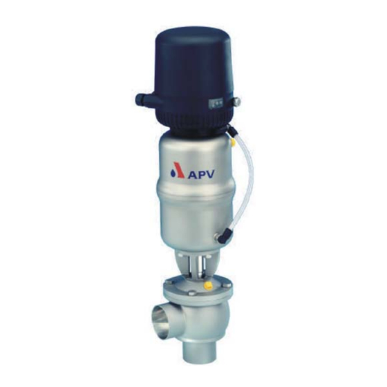
- Page 1 Operating Manual DELTA MF4 Membrane Valve with Bellow Unit Read and understand this manual prior to operating or servicing this product.
-
Page 5: Table Of Contents
DELTA MF4-UK0.qxd / 12.2004 Content Page General Terms Safety Instructions Mode of Operation Auxiliary Equipment Valve position indication (proximity switches) CONTROL UNIT Connections Installation Welding Instructions Dimensions / Weights Technical Data 7 - 8 Opening and closing times kvs values valve stroke / opening section Maintenance Service Instructions... -
Page 7: General Terms
DELTA MF4-UK0.qxd / 12.2004 General Terms This operating manual should be read carefully by the competent operating and maintenance personnel. We point out that we will not accept any liability for damage or malfunctions resulting from the non-compliance with this operating manual. -
Page 8: Mode Of Operation
DELTA MF4-UK0.qxd / 12.2004 Mode of Operation The membrane valves with bellow unit DELTA MF4 have been DELTA MF4 developed for use in the brewing and beverage industries, control unit dairy and food applications as well as in the chemical and DELTA CU pharmaceutical industries. -
Page 9: Auxiliary Equipment
DELTA MF4-UK0.qxd / 12.2004 Auxiliary Equipment Valve position indication (fig. 4.1) fig. 4.1 For the valve position indication, a proximity switch holder (PSH) can be installed direct on the actuator. To signal the limit position of the valve seat, proximity switches can valve position be mounted to the holder if required. -
Page 10: Installation
DELTA MF4-UK0.qxd / 12.2004 Installation - The installation of the valve must be undertaken in such a manner that fluids can drain off the valve housing and should be provided preferably in vertical position. - The valve housing can be welded direct into the pipeline (completely dismantable valve insert). -
Page 11: Dimensions / Weights
DELTA MF4-UK0.qxd / 12.2004 Dimensions / Weights membrane valve with control unit membrane valve with valve positon indicaton (PSH) membrane valve with MEF valve housing weight in kg Ø Di Ø K 14,2 49,5 15,2 inch 1” 17,3 22,2 28,6 1,5”... -
Page 12: Technical Data
DELTA MF4-UK0.qxd / 12.2004 Technical Data Product - wetted parts : 316 L, 1.4404 Other parts : 1.4301 Seals : standard : EPDM Optional : HNBR, VMQ, FPM Bellow unit : 1.4404 /1.4571 Actuator : 1.4301 Max. line pressure : 10bar 135 °... - Page 13 DELTA MF4-UK0.qxd / 12.2004 Technical Data DELTA MF4 Kvs - values in m 3 / h inch 1” 1,5” 2” 2,5” 3” 4” 7.3 valve stroke / opening section (X) dimensions in mm stroke 13,5 17,5 19,5 inch 1” 1,5” 2”...
-
Page 14: Maintenance
DELTA MF4-UK0.qxd / 12.2004 Maintenance - The maintenance intervals depend on the application and should be determined by the operator carrying out temporary checks. - The valve must not be cleaned with products containing abrasive or polishing substances. Especially the valve shafts must not be cleaned with such agents under any circumstances. -
Page 15: Service Instructions
DELTA MF4-UK0.qxd / 12.2004 Service Instructions Dismantling from the line system MF4 / MEF4 The item numbers refer to the spare parts darwings MF4, MEF4: DN design: RN 01.064.6 control unit Inch design: RN 01.064.7 actuator screw a. Shut off line pressure and discharge lines and tanks if possibe. hex. -
Page 16: Installation Of Seals And Assembly Of Valve
DELTA MF4-UK0.qxd / 12.2004 Service Instructions Installation of seals and assembly of valve control unit Provide all seals with a thin layer of grease before their installation. actuator screw a. Insert the guide bush (7) and o-ring (6) into the yoke (8). Fasten the yoke (8) at the actuator (13). - Page 17 DELTA MF4-UK0.qxd / 12.2004 Service Instructions Installation of the valve MF4, MEF4 a. CU design: Fix the adapter at the actuator. Place the control unit (20) on the adapter (22) and secure it with the ring. Valve position indicator: Fasten the indicator housing (18). b.
-
Page 18: Service Instructions Actuator
DELTA MF4-UK0.qxd / 12.2004 Service Instructions Actuator 10.1 Maintenance of Actuator fig. 10.3 a. Remove the air hoses from the actuator. seal screw piston rod b. Remove the inner hex. screws from the adapter of the control unit. v-seal - Remove the adapter. o-ring 10.2 Dismantling of seals... -
Page 19: Service Instructions
DELTA MF4-UK0.qxd / 12.2004 Service Instructions 11.1 Installation of seat seal 1. Before the assembly, provide the seat seal with a thin layer of grease. The groove for the seat seal must not be greased. seat seal seal shoulder groove seal profile seat seal bellow... -
Page 20: Trouble Shooting
DELTA MF4-UK0.qxd / 12.2004 Trouble Shooting Failure Remedy V a l v e c l o s e d a n d p r e s s u r e i n u p p e r h o u s i n g Valve leaks Replace seat seal (2) Check line pressure (max. - Page 22 Phone: +49(0) 23 03/ 108-0 Fax: +49(0) 23 03 / 108-210 For more information about our worldwide locations, approvals, certifications, and local representatives, please visit www.apv.com. Copyright © 2008 SPX Corporation The information contained in this document, including any specifications and other product details, are subject to change without notice.
Need help?
Do you have a question about the APV DELTA MF4 and is the answer not in the manual?
Questions and answers