
Subscribe to Our Youtube Channel
Related Manuals for SPX APV DELTA SVS1F DN 125


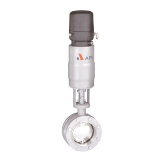
Summary of Contents for SPX APV DELTA SVS1F DN 125
- Page 1 Operating Manual DELTA SVS1F DN 125-250 Butterfly Valve Read and understand this manual prior to operating or servicing this product.
-
Page 5: Table Of Contents
Table of Content Page General Terms Safety Instructions Mode of Operation Auxiliary Equipment Installation 5.1. Welding Instructions Dimensions / Weights Technical Data Materials Maintenance Service Instructions 9 - 11 Trouble Shooting Spare Parts Lists SVS1F - A DN 125 - 250 RN 01.038.020 SVS1F - M DN 125 - 250 RN 01.038.021... -
Page 7: General Terms
General Terms This operating manual has to be read and observed by the responsible operating and maintenance personnel. We have to point out that we will not accept any liability for any damage or malfunctions resulting from the non-compliance with this operating manual. Descriptions and data given herein are subject to technical changes. -
Page 8: Mode Of Operation
Mode of Operation Use of high-quality stainless steel and seal material to the specified requirements, the butterfly valve range DELTA SVS1F is applicable in the food and beverage industries as well as in the chemical and pharmaceutical industries. The function of the butterfly valve is to shut off line sections. Valves of the series DELTA SVS1F can either be operated manually or remote controlled via a pneumatic actuator. - Page 9 Auxiliary Equipment Valve position indication - valve with manual actuation: Specific manual actuations with feedback feature are available: Feedback of both disc positions CU3 control unit open and closed are possible. with adapter CONTROL UNIT Units with feedback switch and solenoid valve for the pneumatic control of the valve for assembly on the actuator are also available in fieldbus technology.
-
Page 10: Installation
Installation In normal installation position, the actuator is vertically to the top. Depending on the requirements of the respective application, the installation position is optional. Valve installation can be undertaken between FG 1 flanges and flanges according to DIN. Attention : Observe welding instructions! 5.1 Welding Instructions - Welding shall only be carried out by certified welders (EN 287 - 1). -
Page 11: Dimensions / Weights
Dimensions / Weights dimensions in mm weights in kg with with manual operation actuator 12,9 20,9 15,6 23,6 24,6 39,6 38,2 53,2 Butterfly Valve DELTA SVS1F DN125-250 Operating Manual rev.2... -
Page 12: Technical Data
Technical Data - max. line pressure 10 bar 135 o C EPDM, HNBR, - max. operating temperature *VMQ, *FPM 140 o C EPDM, HNBR, - short-term load *VMQ, *FPM *(no steam) - vacuum tightness 2 mbar 90 o C - opening angle butterfly valve min. -
Page 13: Maintenance
Maintenance - The maintenance intervals depend on the application of the valve and should be determined by the operator carrying out regular checks of the valve. - There are a few wear parts on SVS1F butterfly valves, principally the SV seal, flange seals and bearings. - It is recommended that spare seals and bearings are kept by the user. -
Page 14: Service Instructions
10. Service Instructions 10.1 Dismantling from the line system a. Shut off the line pressure and drain pipeline if possible. b. Disconnect the pneumatic air line at the turning actuator. c. Release clamp connection at support of proximity switches. Pull off proximity switch. d. - Page 15 10. Service Instructions 10.3 Dismantling of inner parts seal ring, bush bearings, valve disc - Remove all fastening screws (9) around the valve housing and part the housing halves. 10.4 Replacement of seals a. Take the flange seals (4) out of the groove and replace them. Remove the fastening screws (9) of the valve core and part the housing halves.
-
Page 16: Service Instructions
10. Service Instructions 10.6 Installation of the actuating device - Proceed in reverse order to the steps described in 10.2. - With the manually operated butterfly valve, the valve disc and the handle are in a line. - For the assembly of the actuator, see to the requested valve design NC or NO. -
Page 17: Trouble Shooting
11. Trouble Shooting Trouble Remedy Valve is untight Replace seal ring (6), check line pressure. Housing in the flange area is untight Replace flange seal (4). Spindle passage at housing is untight Replace seal ring (6) and bush bearings (5). Air escapes from the air connection Fasten or replace air connection at the pneumatic actuator. - Page 18 Fax: +49(0) 23 03 / 108-210 For more information about our worldwide locations, approvals, certifications, and local representatives, please visit www.apv.com. Copyright © 2008 SPX Corporation The information contained in this document, including any specifications and other product details, are subject to change without notice.
- Page 45 Ventilstellungsmelder (VSM) position indicator Beschreibung ref. - no. Description Rückmeldung komplett (s.Abb.) feedback complete IHP (s. ill.) 15-33-023/33 Initiator mit Leuchtdiode und 5m Kabel proximity switch with LED and 5m cable feedback complete IHPK Rückmeldung komplett IHPK 15-33-140/33 Initiator mit Kabelanschlussraum proximity switch with cable connection und LED housing and LED...
Need help?
Do you have a question about the APV DELTA SVS1F DN 125 and is the answer not in the manual?
Questions and answers