
Subscribe to Our Youtube Channel
Related Manuals for SPX APV DELTA DKRT2


Summary of Contents for SPX APV DELTA DKRT2
- Page 1 Operating Manual DELTA DKRT2 Double - Seat Ball Valve with Cleaning Connection Tank Outlet Valve Read and understand this manual prior to operating or servicing this product.
-
Page 5: Table Of Contents
Table of Contents : Page : General Terms Safety Instructions Mode of Operation Auxiliary Equipment 4 - 5 Cleaning Installation Welding Instructions Materials Dimensions / Weights Technical Data Maintenance Service Instructions 9 - 12 Detection of Seal Damage Spare Parts Lists DKRT - DN50, 80, 100 RN - 01.078 Double - Seat Ball Valve DELTA DKRT 2 Tank Outlet Valve... -
Page 7: General Terms
General Terms This operating manual should be read carefully by the competent operating and maintenance personnel. We point out that we will not accept any liability for damage or malfunctions resulting from the non-compliance with this operating manual. Descriptions and data given herein are subject to technical changes. Safety Instructions Danger! - The line and cleaning system must be depressurized before any... -
Page 8: Mode Of Operation
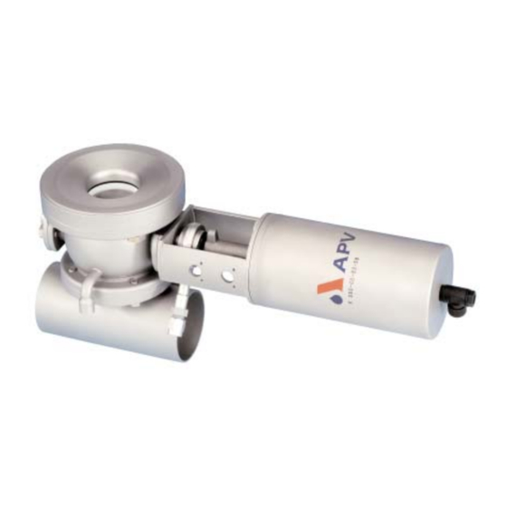
Mode of operation The DKRT 2 double-seat ball valve was particularly developed for the use in applications in which product safety against intermixing is of highest priority. Low tank outlet heights through compact constructions, unreduced flow capacities through pipe diameter - sized balls and double-seal technology guarantee a safe and product-gentle function. -
Page 9: Auxiliary Equipment
Auxiliary Equipment Valve position indication - Switches to signal the limit position of the valve ball can be installed in the yoke if requested. We recommend our APV standard proximity switches. Type: three-wire proximity switch (ref.-No. 08-60-011/93) Operating distance: 4 mm / diameter : 11 mm / length: 30 mm control unit with adapter Feedback complete with support and proximity switch... -
Page 10: Cleaning
Auxiliary Equipment The tank bottom welding flange for the DKRT2 valve tank bottom welding flange does not form part of the scope of supply. Order reference numbers for the tank bottom welding flange: ref.-No.: 31B 31 - 08 - 030/47 31B 31 - 08 - 032/47 31B 31 - 08 - 034/47 Cleaning... -
Page 11: Welding Instructions
Welding Instructions DKRT - Before welding of the valve, the welding flanges must be dismantled from the housing. Tacking or adjustment of the valves should only be undertaken with screwed down welding flanges. - The welding of the mating flanges must be undertaken in such a way that deformation does not occur. -
Page 12: Dimensions / Weights
Dimensions and Weights DKRT 2 with Control Unit CU3 G1/8 DKRT 2 with actuator Dimensions in mm weight in kg 50,0 79,0 102,5 81,0 123,0 16,0 100,0 150,0 19,0 Double - Seat Ball Valve DELTA DKRT 2 Tank Outlet Valve Operating Manual : Rev. -
Page 13: Technical Data
Technical Data - max. line pressure : 10 bar - max. operating temperature : 135 C EPDM, HNBR *FPM, *VMQ - short-term load : 140 C EPDM, HNBR *FPM, *VMQ * no steam - throughput cleaning at 3 bar admission pressure : about 5 - 10 l/min. - Page 14 Service Instructions The item numbers refer to the spare parts drawing (DIN design: RN 01.078) 11.1 Dismantling from the line system a. Shut off connecting lines, lower line pressure and discharge if possible. b. Disconnect pneumatic and electric connections c. Dismantle cleaning line. d.
-
Page 15: Service Instructions
Service Instructions 11.3 Installation of seals and guide bands a. Slightly grease O-rings (5, 6) and guide bands (4) before their installation in the shaft bearings (2). b. Push upper and lower shaft bearing (2) with a little grease in the housing, insert screws (3), but do not tighten them. - Page 16 Service Instructions 11.5 Adjustment of operating position Attention! For a safe, perfect and fast adjustment of the operating position, we recommend to use two separate FG flanges. 11.5.1 Adjustment of operating position with FG flanges (flanges see RN 268.22-1) Install the ball seals as described in 11.3. Assemble the valve as described in 11.4.
- Page 17 Service Instructions 11.5.2 Adjustment of operating position without FG flanges If FG flanges are not available, the ball can, in exceptional cases, be adjusted as follows. (Attention! Failure of adjustement is possible.): Install the ball seals as described in 11.3. Assemble the valve as described in 11.4.
-
Page 18: Detection Of Seal Damage
Detection of Seal Wear The replacement of seals is undertaken as described in the Service Instructions 11. Valve is closed and pressure from the valve ball - Leakage at upper and lower housing flange replace seal (8). - Leakage at the leakage bore replace seals (8, 9, 7). - Page 20 Phone: +49(0) 23 03/ 108-0 Fax: +49(0) 23 03 / 108-210 For more information about our worldwide locations, approvals, certifications, and local representatives, please visit www.apv.com. Copyright © 2008 SPX Corporation The information contained in this document, including any specifications and other product details, are subject to change without notice.
Need help?
Do you have a question about the APV DELTA DKRT2 and is the answer not in the manual?
Questions and answers