
Related Manuals for SPX APV DELTA DE3


Summary of Contents for SPX APV DELTA DE3
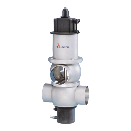
- Page 1 Operating Manual DELTA DE3 Double Seat Mixproof Valve Read and understand this manual prior to operating or servicing this product.
-
Page 5: Table Of Contents
DEL TA DE3-UK4.qxp / 09.2005 Content : Page : General Terms Safety Instructions Mode of Operation 3 - 4 General T erms Valve in "closed" position Valve in "open" position Auxiliary Equipment Valve position indication (proximity switches) CONTROL UNIT Cleaning 6 - 7 Flow areas Leakage chamber... -
Page 7: General Terms
DEL TA DE3-UK4.qxp / 09.2005 General Terms This operating manual should be read carefully by the competent operating and maintenance personnel. We point out that we will not accept any liability for damage or malfunctions resulting from the non-compliance with this operating manual. - Page 8 DEL TA DE3-UK4.qxp / 09.2005 Mode of Operation General Terms Due to its construction and mode of operation as well as to main cylinder the use of high quality stainless steel and adequate seal materials, the double-seat mixproof valve DEL TA DE3 is suited for applications in the food and beverage industries as well as in the pharmaceutical and chemical industries.
-
Page 9: Mode Of Operation
DEL TA DE3-UK4.qxp / 09.2005 Mode of Operation fig. 3.2 Valve in "closed" position (fig 3.2) The lower and upper valve shafts are closed by spring force and safely separate the different fluids . The leakage chamber which is situated between the two valve shafts, provides for a free and absolutely depressurized discharge to the bottom. -
Page 10: Auxiliary Equipment
DEL TA DE3-UK4.qxp / 09.2005 Auxiliary Equipment fig. 4.1 Valve position indication Proximity switches to signal the limit position of the valve shafts DE3 - CU position of can be installed at the actuator if requested (fig. 4.1) proximity switches We recommend to use our APV standard types: operating distance: 5 mm / diameter: 1 1 mm If the customer decides to use valve position indicators other than... -
Page 11: Cleaning
DEL TA DE3-UK4.qxp / 09.2005 Cleaning With the cleaning of DEL TA DE3 valves, one has to distinguish between three areas: The flow areas The upper and lower passages are cleaned by the passing cleaning liquid during the cleaning of the connected pipelines. fig. - Page 12 DEL TA DE3-UK4.qxp / 09.2005 Cleaning Shaft surfaces outside the flow passages (option) fig. 5.3 The DE3 valve provides for those areas of the upper and lower shaft stem which are not subject to cleaning, to be flushed (fig. 5.3) Shaft flushing is recommended with sensible products to increase product safety and the service life of seals.
-
Page 13: Leakage Chamber
DEL TA DE3-UK4.qxp / 09.2005 Installation The valve must be installed in vertical position. Fluids are, therefore, freely drainable from the valve housing and the leakage chamber . Valve housings can be welded direct into the pipelines (completely dismantable valve insert). Attention: Observe welding instructions. -
Page 14: Dimensions / Weights
DEL TA DE3-UK4.qxp / 09.2005 7. Dimensions / Weights Control Unit DELTA CU3 installation dimensions weight dimensions in mm min. in mm in kg Ø Di Ø G 10,1 10,2 10,4 14,6 15,5 30,8 1068 ---- inch 1,5” 34,9 10,1 2”... -
Page 15: Technical Data
DEL TA DE3-UK4.qxp / 09.2005 8. Technical Data fig.8 max. line pressure : 10 bar upper shaft max. operating temperature : 135° C EPDM, HNBR short - term temperature : 140° C EPDM, HNBR tightening torque of stop screw at lower valve shaft : 25Nm tightening torque of safety nut at upper and lower valve shaft... - Page 16 DEL TA DE3-UK4.qxp / 09.2005 8. Technical Data kvs - values in m 800* 500* 1200* 700* inch 1,5” 2” 2,5” 3” 4” 6” 1150* 670* * no measuring value valve position valve position open closed fig. 8.3 table to fig. 8.3 dimensions in mm upper valve shaft...
-
Page 17: Materials
DEL TA DE3-UK4.qxp / 09.2005 Materials product-wetted parts 1.4571, 1.4404 other parts 1.4301 seals: standard EPDM/PTFE option HNBR/PTFE actuator PA 12 GF 30 shaft bearing spray connection PP GF30 Maintenance The maintenance intervals depend on the application and should be determined by the user carrying out regular checks. Compressed air is not required to dismantle the valve. -
Page 18: Service Instructions
DEL TA DE3-UK4.qxp / 09.2005 Service Instructions The item numbers refer to the spare parts drawings valve insert DIN design: RN 01.053.71 Inch design: RN 01.053.71-2 11.1 Dismantling from the piping system Shut off the line pressure in the product and cleaning lines, discharge the pipes if possible. - Page 19 DEL TA DE3-UK4.qxp / 09.2005 Service Instructions 11.2 Dismantling of product-wetted parts (service) Release the 4 inner hex. screws and take With CU design: off the CU adapter . Screw off the stop screw (11) Release the lower safety nut .
-
Page 20: Maintenance Of Main Cylinder
DEL TA DE3-UK4.qxp / 09.2005 Service Instructions 11.3 Maintenance of main cylinder Dismantle the actuator, main cylinder (10) and spring cylinder (8) from the valve insert as described in 11.2 a.-g. 11.3.1 Disassembly of main cylinder and dismantling of seals Remove the fastening screws (14) Remove the main cylinder... - Page 21 DEL TA DE3-UK4.qxp / 09.2005 Service Instructions 11.4 Installation of product-wetted seals and assembly of the DELTA DE3 valve All seals and guides can be serviced. Attention: See to all seals and bearing surfaces in the product area being carefully greased before their assembly.
-
Page 22: Installation Of Valve Insert
DEL TA DE3-UK4.qxp / 09.2005 Service Instructions 11.5 Installation of valve insert Carefully place the valve insert in the valve housing until the screw stops. Remove the pulling screw and carefully press the valve insert into the housing. Screw in the screws and tighten them crosswise. -
Page 23: Disassembly And Assembly Tool
DEL TA DE3-UK4.qxp / 09.2005 12. Disassembly and Assembly Tool (for lower shaft seal, pos. 24, 25) Seal 24, 25 For a simple dismantling and installation of the lower shaft seal, the combi tool (ref.-No. 000 51 -13-100/17) should be used. Support of this tool is especially recommended for valves of the seal lip elastomer seal... -
Page 24: Service Instructions - Shaft Flushing
DEL TA DE3-UK4.qxp / 09.2005 Service Instructions for Shaft Flushing plastic plug Remove the plastic plug. Insert the plug connections and secure them with the safety spring. Insert and fix the supply hose for cleaning liquids in the plug connection. Identification: Insert and fix the discharge hose for cleaning liquids in the plug connection. -
Page 25: Service Instructions - Seat Seals
DEL TA DE3-UK4.qxp / 09.2005 Service Instructions for the Installation of Seat Seals upper seal profile valve shaft Attention: seal lip Shoulder of the seal must be placed evenly seal foot in the seal groove. lower valve shaft (fig. X) shoulder Provide the seal shoulder with a Press a short part of the seal into the groove. -
Page 26: Detection Of Seal Damage
DEL TA DE3-UK4.qxp / 09.2005 Detection of Seal Damage F a i l u r e R e m e d y Leakage at upper housing flange Replace upper shaft seal (24, 25). Leakage at the drain pipe Remove the drain pipe (1) to verify the leakage. Leakage at the outside of the lower valve shaft Replace lower shaft seal (24, 25). - Page 28 Fax: +49(0) 23 03 / 108-210 For more information about our worldwide locations, approvals, certifications, and local representatives, please visit www.apv.com. Copyright © 2008 SPX Corporation The information contained in this document, including any specifications and other product details, are subject to change without notice.
Need help?
Do you have a question about the APV DELTA DE3 and is the answer not in the manual?
Questions and answers