
Related Manuals for SPX APV CU4


Summary of Contents for SPX APV CU4
- Page 1 Instruction Manual Form No.: H323871 Revision: UK-3 Translation of original manual CU4 Direct Connect Read and understand this manual prior Control Unit to operating or servicing this product.
-
Page 3: Table Of Contents
Control Unit CU4 Direct Connect UK-3 / 20.04.2011 Content Page Abbreviations and Definitions Safety Instructions 2 - 4 Sentinels Conventional Use General Regulations for Careful Handling Welding Instructions Persons Warranty General Terms 5 - 7 3.1. Purpose of use Design of CU4 Direct Connect Functional description Mechanics and Pneumatics 8 - 14... -
Page 5: Abbreviations And Definitions
Control Unit CU4 Direct Connect UK-3 / 20.04.2011 Abbreviations and Definitions Exhaust Air American Wire Gauge Communauté Européenne Control Unit Digital Input Digital Output Electromagnetic Compatibility International Protection luminous diode Pneumatic Air Connection NOT element NEMA National Electrical Manufacturers Association Supply Air Connection pulse-width modulation Pneumatic Air Connection... - Page 6 Control Unit CU4 Direct Connect UK-3 / 20.04.2011 Safety Instructions 2.2. Conventional Use The DELTA CU4 control unit is only intended for use as described in chapter 3.1. Use beyond that described in chapter 3.1. is not according to regulations and APV shall not be responsible for any damage resulting from this non-observance.
-
Page 7: Safety Instructions
Control Unit CU4 Direct Connect UK-3 / 20.04.2011 Safety Instructions 2.4. Welding instructions It is generally recommended to avoid welding work in process installation in which control units are installed and connected. If welding is nonetheless required, earthing of the electrical devices in the welding area is a necessity. - Page 8 Control Unit CU4 Direct Connect UK-3 / 20.04.2011 General Terms 3.1. Purpose of use The Control Unit Delta CU4 Direct Connect has been developed for the control of process valves used in the food industry and related industries. The CU4 control unit operates as interface between process control and process valve and controls the electric and pneumatic signals.
-
Page 9: General Terms
Control Unit CU4 Direct Connect UK-3 / 20.04.2011 General Terms 3.3. Function of the individual components The installation of the control unit is undertaken by special adapters which are available for the different valves types, see chapter 5. Adapter. The snap connectors for supply air and pneumatic air to the individual cylinders at the valves are located at the outside of the control unit. - Page 10 Control Unit CU4 Direct Connect UK-3 / 20.04.2011 General Terms 3.3. Function of the individual components The luminous diodes are located on the front side of the electronic module. Their signals are visibly indicated to the outside by an optical window in the cover the control unit. Beside the open and closed valve position, the existence of the operating voltage as well as different diagnostic information are indicated.
-
Page 11: Mechanics And Pneumatics
4.1. connections Control Unit CU4 Direct Connect UK-3 / 20.04.2011 Mechanics and Pneumatics Air connections for turning actuator 4.1.1. Funktion CU41-T-DC design for valve with turning actuator, e.g. butterfly valves. AIR IN air supply with integrated particle filter. bore to transfer control air to turning actuator exhaust air, with exhaust silencer. -
Page 12: Pressure Relief Valve
Control Unit CU4 Direct Connect UK-3 / 20.04.2011 Mechanics and Pneumatics 4.3. Pressure relief valve The base of the control unit is equipped with a pressure relief valve. Which prevents an inadmissible pressure build-up in the inner control unit. If required, the pressure relief vents into the clearance between the base and the adapter of the control unit. - Page 13 Control Unit CU4 Direct Connect UK-3 / 20.04.2011 Mechanics and Pneumatics 4.4. CU41 Direct Connect Functional description - block diagram Power Picture shows a standard NC Power (spring to closed) valve. If NO (spring to open) valve is used, DO Valve closed the sensor wiring can be different.
- Page 14 Control Unit CU4 Direct Connect UK-3 / 20.04.2011 Mechanics and Pneumatics 4.4.1. CU41N Direct Connect Functional description - block diagram Picture shows a standard NC Power (spring to closed) valve. Power If NO (spring to open) valve is used, the sensor wiring can be different. DO Valve closed DO Valve open DO Common...
- Page 15 Control Unit CU4 Direct Connect UK-3 / 20.04.2011 Mechanics and Pneumatics 4.4.2. CU43 Direct Connect for double seat valve DA3 Functional description - block diagram Power Picture shows a standard NC Power (spring to closed) valve. DO Valve closed If NO (spring to open) valve is used, DO Valve open the sensor wiring can be different.
-
Page 16: Technical Data / Standards
Control Unit CU4 Direct Connect UK-3 / 20.04.2011 Mechanics and Pneumatics 4.5. Technical Data / Standards Material: PA6.6 Ambient temperature: -20°C bis +70°C EMC 89/336/EEC Standards and environmental audits: protection class IP 67 EN60529 / complies with NEMA 6 EMV interference resistance EN61000-6-2 EMV emitted interference EN61000-6-4... -
Page 17: Solenoid Valves
Control Unit CU4 Direct Connect UK-3 / 20.04.2011 Mechanics and Pneumatics 4.6. Solenoid valves In the base of the control unit max. 3 solenoid valves are installed. The 3/2-way solenoid valves are connected with the electronic module by moulded cables and plug connectors. control: effected by pwm-signal handle:... - Page 18 Control Unit CU4 Direct Connect UK-3 / 20.04.2011 Adapter Adapter for different process valves 5.1. Valves with turning actuator, e.g. butterfly valves 5.2. Single seat valves 5.3. Double seat valves Control Unit CU4 Direct Connect Instruction Manual: UK-3...
- Page 19 Control Unit CU4 Direct Connect UK-3 / 20.04.2011 Electronic module 6.1. Function / Block diagram The electronic module CU4 Direct Connect operates as interface between superordinated control (PLC) and is connected direct by parallel wiring, i.e. every individual signal is on a separate line.
-
Page 20: Electronic Module
Control Unit CU4 Direct Connect UK-3 / 20.04.2011 Electronic module 6.2. Functional description of connections Terminal Designation Functional description Power Operating voltage Power Operating voltage DO Closed Valve Digital potential-free output for closed valve position DO Open Valve Digital potential-free output for open valve position DO Common Common potential for digital output to valve position indication DI Main Valve... -
Page 21: Technical Data
Control Unit CU4 Direct Connect UK-3 / 20.04.2011 Electronic module 6.3. Technical data for electronic module CU4 Direct Connect Operating voltage: 15 – 48 VDC Supply of solenoid valve: pwm-signal from electronic module Dig. input (DI): 15 – 48 V AC/DC Imax. - Page 22 Control Unit CU4 Direct Connect UK-3 / 20.04.2011 Electronic module 6.4. Connections Sensors to detect the valve positions: Internal sensors: Hall effect sensors, APV type H 320385 UB 4,75-5,25 VDC operating distance according to APV specification External sensors: Inductive proximity switches, APV type H 208844 UB 4,75-5,25 VDC operating distance according to...
-
Page 23: Led Indicators
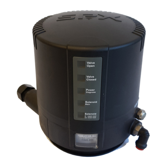
Control Unit CU4 Direct Connect UK-3 / 20.04.2011 Electronic module 6.5. LED indicators External luminous displays colour: green, Valve Open valve in open position permanent light colour: orange, Valve Closed valve in closed position permanent light colour: green, operating voltage at module - faultless permanent light Power Diagnostics... -
Page 24: Wiring Examples
Control Unit CU4 Direct Connect UK-3 / 20.04.2011 Electronic module 6.6. Wiring examples CU4 Direct Connect Example 1 15 - 48VDC Power 5/7 cable required DC supply DC Gnd Power DC valve signal DO Valve closed 2 feedback to SPS DO Valve open common DC mass DO Common... -
Page 25: Feedback Unite
Control Unit CU4 Direct Connect UK-3 / 20.04.2011 Feedback unit 7.1. General terms For the internal registration of the valve position indication, the feedback unit with 2 Hall effect sensors is applied. It is used when single seat and butterfly valves are installed. adjustment screws The control of these sensors is effected by magnets assembled on the valve shaft rod. - Page 26 Control Unit CU4 Direct Connect UK-3 / 20.04.2011 CU Assembly and Start-up 8.1. Turning actuator, e.g. for butterfly valves CU cover CU base with electronic module, sensor tower and solenoid valves clamp ring fastening screws adapter operating cam with permanent magnet turning actuator Caution! The permanent magnet is made of fragile material and must be...
-
Page 27: Cu Assembly And Start-Up
Control Unit CU4 Direct Connect UK-3 / 20.04.2011 CU Assembly and Start-up 8.1.1. Pneumatic connection Supply air: CAUTION Shut off the compressed air supply before connecting the air hose! See that the air hose is professionally cut to length. Use a hose cutter for this purpose. - Page 28 Control Unit CU4 Direct Connect UK-3 / 20.04.2011 CU Assembly and Start-up 8.1.3. Start-up After proper assembly and installation of the control unit, start-up can be undertaken as described below: lever Switch on the air supply. Switch on the voltage supply. Check the solenoid valves by turning the handle on the upper side of the valve by 90°.
-
Page 29: Single Seat Valves
Control Unit CU4 Direct Connect UK-3 / 20.04.2011 CU Assembly and Start-up 8.2. Single seat valves CU cover CU base with electronic module, sensor tower and solenoid valves clamp ring fastening screws adapter operating cam with actuator permanent magnet CAUTION The permanent magnet is made of fragile material and must be protected against mechanical load . - Page 30 Control Unit CU4 Direct Connect UK-3 / 20.04.2011 CU Assembly and Start-up 8.2.1. Pneumatic connection Supply air: CAUTION Shut off the compressed air supply before connecting the air hose! See that the air hose is professionally cut to length. Use a hose cutter for this purpose.
- Page 31 Control Unit CU4 Direct Connect UK-3 / 20.04.2011 CU Assembly and Start-up 8.2.3. Start-up After proper assembly and installation of the control unit, start-up can be undertaken as described below: lever Switch on the air supply. Switch on the voltage supply. Check the solenoid valves by turning the handle on the upper side of the valve by 90°.
-
Page 32: Double Seat Valves
Control Unit CU4 Direct Connect UK-3 / 20.04.2011 CU Assembly and Start-up Double seat valves 8.3. CU cover CU41/CU43 clamp ring fastening screws adapter feedback 1 for closed valve position seat lift cylinder air actuator external proximity switches spring cylinder feedback 2 for open valve position... - Page 33 Control Unit CU4 Direct Connect UK-3 / 20.04.2011 CU Assembly and Start-up 8.3.1. Pneumatic connection Supply air: CAUTION Shut off the compressed air supply before connecting the air hose! See that the air hose is professionally cut to length. Use a hose cutter for this purpose.
- Page 34 Control Unit CU4 Direct Connect UK-3 / 20.04.2011 CU Assembly and Start-up 8.3.3. Connection of external proximity switches The electric connection of the proximity switches specified by APV is undertaken according to the terminal layout described in chapter 6.1. lever The mechanic assembly of the proximity switches is carried out at the actuator of the corresponding double seat valves.
-
Page 35: Accessories And Tools
Control Unit CU4 Direct Connect UK-3 / 20.04.2011 Accessories and Toolszeuge Assembly/disassembly - adapter on valve actuator: • hexagon socket wrench 6 mm • screwdriver 4mm Assembly/disassembly – CU on adapter: • hexagon socket wrench 3 mm Assembly/disassembly – electronic module: •... -
Page 36: Disassembly
Control Unit CU4 Direct Connect UK-3 / 20.04.2011 Disassembly 10.1. Demontage Before disassembly, verify the following items: • The valve must be in safety position and must not be controlled! • Shut off air supply! • Cut off current to control unit, i.e. interrupt the supply voltage! Solenoid valve (4, 5, 6) Open the CU cover by turning in anticlockwise direction. -
Page 37: Trouble Shooting
Control Unit CU4 Direct Connect UK-3 / 20.04.2011 Trouble Shooting F a i l u r e R e m e d y Valve position is not indicated. Re-adjust Hall sensors. Check fastening of magnetic operating cam. Check cabeling of the Hall sensors to the electronic module. -
Page 38: Spare Parts Lists
Control Unit CU4 Direct Connect UK-3 / 20.04.2011 Trouble Shooting F a i l u r e R e m e d y Control Unit CU41 installed on Single seat and Double seat valves Check if right control unit is installed. Valve position movement is missing Check label in type window of control unit: with actuated solenoid valve. - Page 40 Phone: +49 (0) 2303-108-0 Fax +49 (0) 2303-108-210 SPX reserves the right to incorporate our latest design and material changes without notice or obligation. Design features, materials of construction and dimensional data, as described in this bulletin, are provided for your information only and should not be relied upon unless confirmed in writing.
- Page 41 Datum: 07/08 08/08 11/08 02/10 06/10 Name: Peters Peters Peters Peters D.Schulz Geprüft: D.Schulz Ersatzteilliste: spare parts list APV Rosista GmbH, D-59425 Unna Germany Blatt CU4 Direct Connect RN 01.044.4...
Need help?
Do you have a question about the APV CU4 and is the answer not in the manual?
Questions and answers