Table of Contents
Advertisement
Available languages
Available languages
Quick Links
DE
Einbau- und Bedienungsanleitung
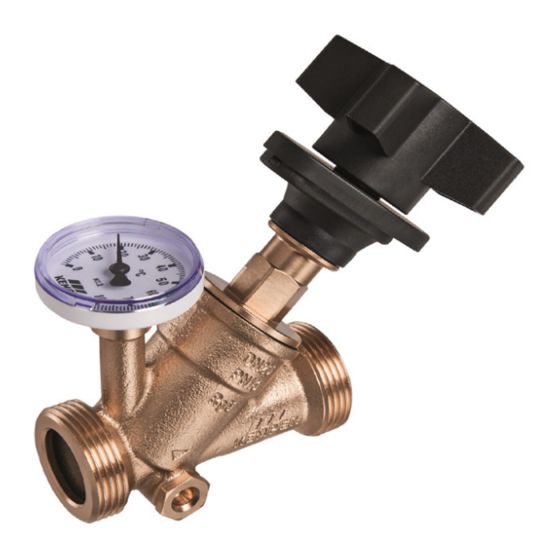
KEMPER MULTI-FIX-PLUS manuelles Zirkulations-Regulierventil
Figur 150 6G | Figur 151 06
EN
Installation and Operating Instructions
KEMPER MULTI-FIX-PLUS Double-Regulating Valve
Figure 150 6G | 151 06
NL
Installatie- en bedieningshandleiding
KEMPER MULTI-FIX-PLUS inregelafsluiter
Figuur 150 6G | 151 06
Figur 150 6G (AG)
!
Figur 151 06 (IG)
2
7
12
Advertisement
Chapters
Table of Contents

Related Manuals for Kemper Figure 150 6G


Summary of Contents for Kemper Figure 150 6G
- Page 1 KEMPER MULTI-FIX-PLUS manuelles Zirkulations-Regulierventil Figur 150 6G | Figur 151 06 Installation and Operating Instructions KEMPER MULTI-FIX-PLUS Double-Regulating Valve Figure 150 6G | 151 06 Installatie- en bedieningshandleiding KEMPER MULTI-FIX-PLUS inregelafsluiter Figuur 150 6G | 151 06 Figur 150 6G (AG)
-
Page 2: Table Of Contents
Verletzungen oder Sachschä- anzeige dient zum hydraulischen Strangab- den führen! gleich von Zirkulationssträngen und der Einregulierung von Volumenströmen. Das Produkt ist ausschließlich für den beschrie- benen Zweck zu verwenden. 2 /20 – K41001506G001-00 / 02.2022 – © www.kemper-olpe.de... -
Page 3: Sicherheitshinweise Für Montage
Desinfektion (T > 70 °C) von Sanitärinstalla- DVGW W 553 tionen. DIN 1988-300 Entsorgung Örtliche Vorschriften zur Abfall verwertung bzw. -beseitigung sind zu beachten. Produkt darf nicht mit normalem Haushalts müll, sondern muss sachgemäß entsorgt werden. © www.kemper-olpe.de – 02.2022 / K41001506G001-00 – 3 /20... -
Page 4: Technische Daten
Zur Inbetriebnahme des Rohrsystems den passenden Einstellwert wählen. Funktionsbeschreibung Das Ventil realisiert genau definierte Volumenströme. Dies geschieht durch ein den Anfor- derungen entsprechendes Ventil mit einem Regulierkegel. Es ermöglicht den hydraulischen Abgleich der Zirkulationsstränge untereinander. 4 /20 – K41001506G001-00 / 02.2022 – © www.kemper-olpe.de... -
Page 5: Beispiel Für Die Einstellung Des Regulierventils
Drehen der Einstellkappe werte sind stufenlos einstellbar. bis zum Anschlag fixieren. Nach der Fixierung kann das MULTI-FIX-PLUS noch geschlossen werden, aber nicht mehr weiter als die Einstellfixierung geöffnet werden. Einstellwert-Skala © www.kemper-olpe.de – 02.2022 / K41001506G001-00 – 5 /20... -
Page 6: Zubehör Und Ersatzteile
1870000600 Temperaturfühler Pt1000 T510014000003KP Ersatzteilliste Benennung Figur/Bestellnr. Ersatzoberteil DN 15 E010915002015KP Ersatzoberteil DN 20 E010915002020KP Ersatzoberteil DN 25 E010915002025KP Ersatzoberteil DN 32 E010915002032KP Ersatzoberteil DN 40 E010915002040KP Ersatzoberteil DN 50 E010915002050KP 6 /20 – K41001506G001-00 / 02.2022 - © www.kemper-olpe.de... - Page 7 The product must only be used for this purpose. Only use the Double-Regulating Valve - in sound condition. - as intended. © www.kemper-olpe.de – 02.2022 / K41001506G001-00 – 7 /20...
-
Page 8: Safety Instructions For Installation
DVGW W 551 cycling and disposal must be DVGW W 553 followed. The product must DIN 1988-300 not be disposed of with household waste but must rather be disposed of appro- priately. 8 /20 – K41001506G001-00 / 02.2022 – © www.kemper-olpe.de... -
Page 9: Technical Specifications
The valve implements precisely defined volume flows. This is accomplished through a valve with regulating cone that corresponds to the requirements. It enables the hydraulic align- ment of the circulation branches to each other. © www.kemper-olpe.de – 02.2022 / K41001506G001-00 – 9 /20... -
Page 10: Example For The Setting Of The Regulation Valve
After pre-setting the Multi-Fix Plus, the valve can be used to isolate the pipe and re-opened not further than the pre-setting value pre-set value. 10 /20 – K41001506G001-00 / 02.2022 – © www.kemper-olpe.de... -
Page 11: Accessories And Spare Parts
Figure/Part No. Spare Head-part DN 15 E010915002015KP Spare Head-part DN 20 E010915002020KP Spare Head-part DN 25 E010915002025KP Spare Head-part DN 32 E010915002032KP Spare Head-part DN 40 E010915002040KP Spare Head-part DN 50 E010915002050KP © www.kemper-olpe.de – 02.2022 / K41001506G001-00 – 11 /20... -
Page 12: Veiligheidsinstructies Voor Montage
De MULTI-FIX-PLUS inregelafsluiter met materiële schade leiden! temperatuur- en positie-indicator wordt in- gezet voor het inregelen van de hydraulische balans in warmtapwatercirculatiesystemen. Het product mag uitsluitend voor het be- schreven gebruik toegepast worden. 12 /20 – K41001506G001-00 / 02.2022 – © www.kemper-olpe.de... - Page 13 Het product mag niet bij het gewone huisvuil, maar moet vakkundig worden afgevoerd. © www.kemper-olpe.de – 02.2022 / K41001506G001-00 – 13 /20...
-
Page 14: Technische Specificaties
Inregelafsluiter altijd in stroomrichting inbouwen (zie pijl op de behuizing). Voor de inbedrijfstelling van het leidingsysteem de juiste waarde instellen. Functiebeschrijving De inregelafsluiter regelt nauwkeurig gedefinieerde volumestromen. De inregelafsluiter maakt de hydraulische balans in het circulatiesysteem mogelijk. 14 /20 – K41001506G001-00 / 02.2022 – © www.kemper-olpe.de... -
Page 15: Voorbeeld Van Het Instellen Van De Inregelafsuiter
Na het fixeren kan handwiel. Alle tussenwaarden zijn de MULTI-FIX-PLUS nog gesloten traploos instelbaar. worden, maar verandert de ingestelde waarde niet meer. Instelwaarde-indicator © www.kemper-olpe.de – 02.2022 / K41001506G001-00 – 15 /20... -
Page 16: Toebehoren En Onderdelen
1870000600 Temperatuursensor Pt1000 T510014000003KP Ersatzteilliste Omschrijving Figuur/Art.-nr. Bovendeel DN 15 E010915002015KP Bovendeel DN 20 E010915002020KP Bovendeel DN 25 E010915002025KP Bovendeel DN 32 E010915002032KP Bovendeel DN 40 E010915002040KP Bovendeel DN 50 E010915002050KP 16 /20 – K41001506G001-00 / 02.2022 – © www.kemper-olpe.de... -
Page 17: Flowdiagrammen
Voorbeeld © www.kemper-olpe.de – 02.2022 / K41001506G001-00 – 17 /20... - Page 18 18 /20 – K41001506G001-00 / 02.2022 – © www.kemper-olpe.de...
- Page 19 © www.kemper-olpe.de – 02.2022 / K41001506G001-00 – 19 /20...
- Page 20 Service-Hotline +49 2761 891-800 Gebr. Kemper GmbH + Co. KG Harkortstraße 5 www.kemper-olpe.de info@kemper-olpe.de D-57462 Olpe 20 /20 – K41001506G001-00 / 02.2022 – © www.kemper-olpe.de...
Need help?
Do you have a question about the Figure 150 6G and is the answer not in the manual?
Questions and answers