
Related Manuals for Cincoze CO-100/P1101 Series


Summary of Contents for Cincoze CO-100/P1101 Series
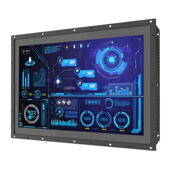
- Page 1 CO-100/P1101 Series User Manual Open Frame Panel PC TFT Full HD 16:9 Panel PC with Intel® Atom® / Pentium® Processor Version: V1.00...
-
Page 2: Table Of Contents
Contents Preface ..........................5 Copyright Notice ........................5 Acknowledgement .........................5 Disclaimer ..........................5 Declaration of Conformity ......................6 Product Warranty Statement ....................6 Technical Support and Assistance ..................8 Conventions Used in this Manual ..................8 Safety Precautions.........................9 Package Contents ....................... 10 Ordering Information ......................10 Chapter 1 Product Introductions ..................11 1.1 Overview ........................ - Page 3 3.8 Installing a SIM Card ....................40 3.9 Disassemble the CO Display Module ..............41 3.10 Standard Mount ....................42 3.11 Flat Mount ......................44 3.12 Disassemble the mounting brackets ..............50 Chapter 4 BIOS Setup ......................52 4.1 BIOS Introduction ....................53 4.2 Main Setup ......................
- Page 4 6.4 Installing VESA Mount .................... 86 6.5 Installing Rack Mount ..................... 88 Series | User Manual CO-100/P1101...
-
Page 5: Preface
2022/09/05 Copyright Notice © 2022 by Cincoze Co., Ltd. All rights are reserved. No parts of this manual may be copied, modified, or reproduced in any form or by any means for commercial use without the prior written permission of Cincoze Co., Ltd. All information and specification provided in this manual are for reference only and remain subject to change without prior notice. -
Page 6: Declaration Of Conformity
Product Warranty Statement Warranty Cincoze products are warranted by Cincoze Co., Ltd. to be free from defect in materials and workmanship for 2 years (2 Years for PC Module, 1 Year for Display Module) from the date of purchase by the original purchaser. During the warranty period, we shall, at our option, either repair or replace any product that proves to be defective under normal operation. - Page 7 Limitation of Liability Cincoze’ liability arising out of the manufacture, sale, or supplying of the product and its use, whether based on warranty, contract, negligence, product liability, or otherwise, shall not exceed the original selling price of the product. The remedies provided herein are the customer’s sole and exclusive remedies.
-
Page 8: Technical Support And Assistance
Technical Support and Assistance 1. Visit the Cincoze website at www.cincoze.com where you can find the latest information about the product. 2. Contact your distributor or our technical support team or sales representative for technical support if you need additional assistance. Please have following information ready before you call: ⚫... -
Page 9: Safety Precautions
Safety Precautions Before installing and using this device, please note the following precautions. Read these safety instructions carefully. Keep this User’s Manual for future reference. Disconnected this equipment from any AC outlet before cleaning. For plug-in equipment, the power outlet socket must be located near the equipment and must be easily accessible. -
Page 10: Package Contents
Package Contents Before installation, please ensure all the items listed in the following table are included in the package. Item Description Q’ty CO-W121C/P1101 Series Panel PC Utility DVD Driver DIO Terminal Block Connector (Female) Thermal Pad (for CPU Thermal Block) Power Terminal Block Connector (Female) Screw Pack Remote Power On/Off Terminal Block Connector... -
Page 11: Chapter 1 Product Introductions
Chapter 1 Product Introductions Series | User Manual CO-100/P1101... -
Page 12: Overview
1.1 Overview Cincoze power efficient open frame modular panel PCs (CO-W121C/P1101 Series) support Intel® Atom® and Pentium® processors, and multiple displays. Native I/O ports include LAN, USB, COM, and DIO, and the series supports CFM technology, offering expansion functions such as Power Ignition Sensing (IGN) to meet different application needs. -
Page 13: Key Features
1x DDR3L SO-DIMM max. up to 8GB ⚫ Designed with Adjustable Mounting Bracket ⚫ Support Flat / Standard / VESA / Rack Mount ⚫ Front Panel IP65 Compliant ⚫ Wide Operating Temperature ⚫ Cincoze Patent CDS Technology Support Series | User Manual CO-100/P1101... -
Page 14: Co-W121C-R10/P1101 Series
1.4 Hardware Specification 1.4.1 CO-W121C-R10/P1101 Series The table on this page refers to the specifications of CO-W121 alone. Display • 21.5” (16:9) LCD Size • 1920 x 1080 Resolution • 300 cd/m2 Brightness • 5000:1 Contract Ratio • 16.7M LCD Color •... - Page 15 Model Name P1101 System Processor • Onboard Intel® Atom® x7-E3950 Quad Core Processor, up to 2.00 GHz • Onboard Intel® Pentium® N4200 Quad Core Processor, up to 2.50 GHz Memory • 1x DDR3L 1333/1600/1866 MHz 204-Pin SO-DIMM Socket • Support up to 8 GB (un-buffered and non-ECC) Graphics Graphics Engine •...
- Page 16 Model Name P1101 Other Function • Support 0.2sec Instant Reboot • Software Programmable Supports 256 Levels System Reset Watchdog Timer • AMP 2W + 2W Internal Speaker • LCD On/Off, Brightness Up, Brightness Down OSD Function Power • Support AT, ATX Mode AT/ATX Power •...
- Page 17 Dimension CO-W121C/P1101 Unit: mm Series | User Manual CO-100/P1101...
-
Page 18: System I/O
1.5 System I/O 1.5.1 Front HDD LED Antenna Indicates the status of the hard drive Used to install an antenna jack Removable HDD SIM Card Used to inserts a 2.5” HDD/SSD Used to inserts a SIM card Power On/Off Switch AT/ATX Switch Press to power-on or power-off the system Used to select AT or ATX power mode... -
Page 19: Left
1.5.3 Left Temperature LED Decrease Brightness Indicates the temperature of the system Press to decrease brightness of the screen Reset LCD On/Off Used to reset the system Press to turn-on or turn-off the display Antenna USB 3.0 Used to install an antenna jack Used to connect USB 3.0/2.00 device Increase Brightness COM3, COM4... -
Page 20: Chapter 2 Switches & Connectors
Chapter 2 Switches & Connectors Series | User Manual CO-100/P1101... -
Page 21: Location Of Switches And Connectors
2.1 Location of Switches and Connectors 2.1.1 Top View Series | User Manual CO-100/P1101... -
Page 22: Bottom View
2.1.2 Bottom View Series | User Manual CO-100/P1101... -
Page 23: Switches And Connectors Definition
2.2 Switches and Connectors Definition List of Switches & Connectors Location Definition AT_ATX AT / ATX Power Mode Switch CLR_CMOS Clear CMOS Switch RESET1 Reset Button BL_UP1 Backlight Increase Button BL_UP2 Backlight Decrease Button BL_PWR1 Backlight Power On / Off Button USB3_1 / USB3_2 / USB 3.0 Ports USB3_3... -
Page 24: Definition Of Switches
2.3 Definition of Switches AT_ATX: AT / ATX Power Mode Switch Switch Definition 1-2 (Left) AT Power Mode 2-3 (Right) ATX Power Mode (Default) CLR_CMOS: Clear CMOS Switch Switch Definition 1-2 (Left) Normal Status (Default) 2-3 (Right) Clear CMOS BL_PWR1: Backlight Power on / off Switch Definition Push... - Page 25 SW1: Super CAP SW / COM3~4 with Power Select Location Function DIP1 DIP2 Enabled ON (Default) Super Disabled Location Function DIP3 DIP4 0V (RI) ON (Default) ON (Default) COM3 Location Function DIP5 DIP6 0V (RI) ON (Default) ON (Default) COM4 SW2: COM1~2 with Power Select Location Function...
-
Page 26: Definition Of Connectors
2.4 Definition of Connectors MINIPCIE1 : Mini PCI-Express Socket (Support SIM Card to Link feature) Pin Definition Definition Pin Definition WAKE# 37 RESERVED 3.3V 3.3V 38 USB_D+ 39 RESERVED PERST# 40 GND PERN0 (USB3RN0) / 41 3.3V SATARP0 1.5V 3.3V 42 NA PERP0 (USB3RP0) / CLKREQ#... - Page 27 MINIPCIE2 : Mini PCI-Express Socket (Support mSATA feature) Pin Definition Definition Pin Definition WAKE# 37 GND 3.3V 3.3V 38 USB_D+ 39 3.3V PERST# 40 GND PERN0 / SATARP0 41 3.3V 1.5V +3.3VAUX 42 NA CLKREQ# PERP0 / SATARN0 43 GND 44 NA 45 NA 10 NA...
- Page 28 PWR_SW2: Remote Power On/Off Connector Definition PWR_SW Do not apply power to this connector! This port is used to connect a SWITCH! DC_IN1: DC Power Input Connector (+9~48V) Connector Type: Terminal Block 1x3 3-pin, 5.0mm pitch Definition +9~48V IN Ignition (IGN) Please disconnect the power source before mounting the DC power cables or connecting the DC power connector to system.
- Page 29 COM1_1 / COM2_1 / COM3_1 / COM4_1: RS232 / RS422 / RS485 Connector Connector Type: 9-pin D-Sub RS422 / 485 RS485 RS232 Full Duplex Half Duplex Definition Definition Definition DATA - DATA + POWER1/ POWER2: Power Connector Connector Type: 1x4 4-pin Wafer, 2.0mm pitch Pin 1 Definition +12V...
-
Page 30: Chapter 3 System Setup
Chapter 3 System Setup Series | User Manual CO-100/P1101... -
Page 31: Removing The Top Cover
3.1 Removing the Top Cover 1. Loosen the 8 screws of front and rear panel, then place them aside. 2. Remove the cover from the chassis. Place the top cover gently. Series | User Manual CO-100/P1101... -
Page 32: Installing So-Dimm Memory
3.2 Installing SO-DIMM Memory 1. Locate the SO-DIMM sockets. 2. Tilt the SO-DIMM module at a 45-degree angle and insert it to SO-DIMM socket until the gold-pated connector of module contacted firmly with the socket. 45° 3. Press the modules down until it’s fixed firmly by the two locking latches on each side. Series | User Manual CO-100/P1101... -
Page 33: Installing Mini-Pcie Cards
3.3 Installing Mini-PCIe Cards (Applicable for full or half size card) Locate the Mini PCIe slot. Insert the Mini-PCIe card at a 45-degree angle and insert it to the slot until the gold-pated connector of module contacted firmly with the slot. 45°... -
Page 34: Installing Antennas
If you have a Half-size Mini-PCIe card, make sure use extender to make it Full-size as shown below. 3.4 Installing Antennas 1. Remove the antenna hole covers at front panel. 2. Have antenna jack penetrate through the hole. Series | User Manual CO-100/P1101... - Page 35 3. Put on washer and fasten the nut with antenna jack. 4. Assemble the antenna and antenna jack together. 5. Attach the RF connector at another end of cable onto the module. Series | User Manual CO-100/P1101...
-
Page 36: Installing Cpu Thermal Pad
3.5 Installing CPU Thermal Pad 1. Place the thermal pad on the CPU heatsink. thermal pad Before assembling the system’s chassis cover, please make sure the protective film on the Thermal Pad has been removed! Series | User Manual CO-100/P1101... -
Page 37: Assembling The System
3.6 Assembling the System 1. Put on the cover. 2. Fasten the 8 screws to fix the cover. Series | User Manual CO-100/P1101... -
Page 38: Installing A Sata Hard Drive
3.7 Installing a SATA Hard Drive 1. Loosen 2 screws on front panel to remove cover plate. 2. Turn over the unit to have the bottom side face up and loosen 1 screw. 3. Pull out the HDD bracket. Series | User Manual CO-100/P1101... - Page 39 4. Make the bottom side of the HDD face up, place the HDD bracket on it. Ensure the direction of bracket is correct and use 4 provided screws to assemble HDD and HDD bracket together. 5. Align the HDD bracket with the entrance of HDD bay. And insert the HDD bracket until the connector of HDD contact the SATA connector firmly.
-
Page 40: Installing A Sim Card
3.8 Installing a SIM Card 1. Loosen 2 screws on front panel to remove cover plate. 2. SIM card slot is at the front panel of the system. 3. Insert the SIM card. Series | User Manual CO-100/P1101... -
Page 41: Disassemble The Co Display Module
3.9 Disassemble the CO Display Module The complete shipping product is the CO display module already installed on the P1100. This chapter will introduce how to dissemble CO display module and P1100. 1. Remove the 6 screws on the display module. 2. -
Page 42: Standard Mount
3.10 Standard Mount Before doing the following steps, please make sure the screw positions are fastened at the default positions as indicated in the following picture. The default positions are the correct positions for Standard Mount, so it does not need to change the screw positions additionally for Standard Mount. - Page 43 2. Fasten the screws from the rack’s front side. Please prepare 12 x M4 screws for fixing the module through the screw holes as shown below. User can also prepare 16 x M4 screws for fixing the module through the oblong holes as shown below.
-
Page 44: Flat Mount
3.11 Flat Mount 1. Locate the left and right-side mounting brackets. 2. Remove the two screws on the left and right-side mounting brackets. 3. Loosen the three screws on the left and right-side mounting brackets. Series | User Manual CO-100/P1101... - Page 45 4. Measure the rack thickness. The thickness is measured 3mm in this example. 5. According to the thickness = 3mm for the example, push down the left and right-side mounting brackets to the place at screw hole = 3mm. 6. Fasten the two screws on the left and right-side mounting brackets. Series | User Manual CO-100/P1101...
- Page 46 7. Fasten the three screws on the left and right-side mounting brackets. 8. Locate the top and bottom-side mounting brackets. 9. Remove the two screws on the top and bottom-side mounting brackets. Series | User Manual CO-100/P1101...
- Page 47 10. Loosen the three screws on the top and bottom-side mounting brackets. 11. According to the thickness = 3mm for the example, push down the top and bottom-side mounting brackets to the place at screw hole = 3mm. 12. Fasten the two screws on the top and bottom-side mounting brackets. 13.
- Page 48 14. Put the CO-100 module onto the rack back side. 15. Fasten the screws from the rack’s front side. Please prepare 12 x M4 screws for fixing the module through the screw holes as shown below. Series | User Manual CO-100/P1101...
- Page 49 User can also prepare 16 x M4 screws for fixing the module through the oblong holes as shown below. Series | User Manual CO-100/P1101...
-
Page 50: Disassemble The Mounting Brackets
3.12 Disassemble the mounting brackets Before the installation of VESA mount and rack mount, user need to disassemble the mounting brackets on the CO display module first. 1. Remove the 8 screws. 2. Remove the 3 screws on the left and right side of mounting brackets. Series | User Manual CO-100/P1101... - Page 51 3. Remove the 3 screws on the top and bottom side of mounting brackets. 4. Remove the four mounting brackets. Series | User Manual CO-100/P1101...
-
Page 52: Chapter 4 Bios Setup
Chapter 4 BIOS Setup Series | User Manual CO-100/P1101... -
Page 53: Bios Introduction
4.1 BIOS Introduction The BIOS (Basic Input/ Output System) is a program located on a Flash Memory on the motherboard. When you start the computer, the BIOS program will gain control. The BIOS first operates an auto-diagnostic test called POST (power on self-test) for all the necessary hardware, it detects the entire hardware device and configures the parameters of the hardware synchronization. -
Page 54: Main Setup
4.2 Main Setup Press <Del> to enter BIOS CMOS Setup Utility, the Main Menu (as shown below) will appears on the screen. Use arrow keys to move among the items and press <Enter> to accept or enter a sub-menu. 4.2.1 System Date Set the date. -
Page 55: Advanced Setup
4.3 Advanced Setup This section allows you to configure and improve your system and allows you to set up some system features according to your preference. 4.3.1 Trusted Computing Settings ■ Security Device Support [Enabled] Enables or disables Security Device Support function. ■... -
Page 56: Acpi Settings
■ SHA256 PCR Bank [Enabled] Enables or disables SHA256 PCR Bank function. ■ Pending Operation [None] Allows you to select which mode Pending Operation will operate. Configuration options: [None], [TPM Clear] ■ Platform Hierarchy [Enabled] Enables or disables Platform Hierarchy function. ■... -
Page 57: F81866 Super Io Configuration
Allows users to select the highest Advanced Configuration Power Interface® (ACPI) sleep state that system will enter when suspend button is pressed. [Suspend Disabled]: Disables entering suspend state. [S3 (suspend to RAM)]: Enables suspend to RAM state. ■ Lock Legacy Resources [Enabled] Enables or disables Lock Legacy Resources. -
Page 58: Hardware Monitor
❑ Serial Port [Enabled] Enables or disables serial port. ❑ Change Settings [Auto] Allows you to change the IO Address & IRQ settings of the specified serial port. ❑ Onboard Serial Port 1~6 Mode [RS232] Allows you to select Serial Port Mode. Configuration options: [RS232] [RS422/RS485 Full Duplex] [RS485 Half Duplex] ■... -
Page 59: S5 Rtc Wake Settings
4.3.5 S5 RTC Wake Settings ■ Wake system from S5 [Disabled] Enables or disables wake system from S5 (soft-off state). [Disabled]: Disables wake system from S5. [Fixed Time]: Sets a fixed time (HH:MM:SS) to wake system from S5. [Dynamic Time]: Sets an increase minute(s) from current time to wake system from S5. 4.3.6 Serial Port Console Redirection ■... -
Page 60: Cpu Configuration
4.3.7 CPU Configuration ■ Socket 0 CPU Information This section provides information on your CPU, frequency, and cache memory. ■ Active Processor Cores [Enabled] Number of cores to enable in each processor package. ■ Intel Virtualization Technology [Enabled] Enables or disables Intel Virtualization Technology. Virtualization enhanced by Intel Virtualization Technology will allow a platform to run multiple operating systems and applications in independent partitions. -
Page 61: Csm Configuration
■ Network Stack [Disabled] Enables or disables UEFI Network Stack. 4.3.9 CSM Configuration This option controls legacy/UEFI ROMs priority. ■ CSM Support [Disabled] Enables or disables compatibility support module. ■ Boot option filter [UEFI and Legacy] Allows you to select which type of operating system to boot. [UEFI and Legacy]: Allows booting from operating systems that support legacy option ROM or UEFI option ROM. -
Page 62: Usb Configuration
Controls the execution of UEFI and Legacy Video option ROM. [Do not launch]: Disables option ROM execution. [UEFI]: Enables UEFI option ROM only. [Legacy]: Enables legacy option ROM only. ■ Other PCI devices [Do not launch] Allows users to determine option ROM execution policy for devise other than network, storage, or video. -
Page 63: Chipset Setup
4.4 Chipset Setup This section allows you to configure chipset related settings according to user’s preference. 4.4.1 North Bridge This section provides information on the installed memory size and memory/onboard graphics-related configuration options. Series | User Manual CO-100/P1101... -
Page 64: South Bridge
4.4.2 South Bridge ■ OS Selection [Windows] Allows you to configure Operating System version to install. Configuration options: [Windows] [Intel Linux] ■ Mini PCIE1/USB3 Switch [Mini PCIE] Allows you to change Mini PCIE1 as [Mini PCIE] or [USB3]. ■ Mini PCIE2/mSATA Switch [Mini PCIE] Allows you to change Mini PCIE2 as [Mini PCIE] or [mSATA]. -
Page 65: South Cluster Configuration
4.4.3 South Cluster Configuration ■ PCI Express Configuration PCI Express Root Port 5 (MiniPcie2) ❑ PCI Express Root Port 5 (MiniPcie2) [Enabled] Enables or disables PCI Express Root Port. ❑ PCIe Speed [Auto] Allows you to select PCI Express port speed. Configuration options: [Auto] [Gen1] [Gen2]. - Page 66 PCI Express Root Port 6 (MiniPcie) ❑ PCI Express Root Port 6 (MiniPcie) [Enabled] Enables or disables PCI Express Root Port. ❑ PCIe Speed [Auto] Allows you to select PCI Express port speed. Configuration options: [Auto] [Gen1] [Gen2]. ■ SATA Devices SATA Port 0 ❑...
- Page 67 ■ Miscellaneous Configuration ❑ Restore AC Power Loss [Last state] Allows you to specify which power state system will enter when power is resumed after a power failure (G3 state). [Always on]: Enters to power on state. [Always off]: Enters to power off state. [Last state]: Enters to the last power state before a power failure sables.
-
Page 68: Security Setup
4.5 Security Setup This section allows users to configure BIOS security settings. 4.5.1 Administrator Password Administrator Password controls access to the BIOS Setup utility. 4.5.2 User Password User Password controls access to the system at boot and to the BIOS Setup utility. Series | User Manual CO-100/P1101... -
Page 69: Boot Setup
4.6 Boot Setup This section allows you to configure Boot settings. ■ Bootup NumLock State Allows you to set NumLock key to [On] or [Off] state when system boots up. ■ Quiet Boot Allows you to enable or disable Quiet Boot function. ■... -
Page 70: Save & Exit
4.7 Save & Exit ■ Save Changes and Reset This item allows you to reset the system after saving changes. ■ Discard Changes and Reset This item allows you to reset system setup without saving any changes. ■ Restore Defaults This item allows you to restore/ load default values for all the setup options. -
Page 71: Chapter 5 Product Application
Chapter 5 Product Application Series | User Manual CO-100/P1101... -
Page 72: Digital I/O (Dio) Application
This section describes DIO application of the product. The content and application development are better understood and implemented by well experienced professionals or developers. 5.1.1 Digital I/O Programming Guide 5.1.1.1 Pins for Digital I/O of Cincoze P1101 series product Item Standard GPIO74 (Pin107) - Page 73 -o 4e 87 -o 4e 87 (enable configuration) -o 4e aa (disable configuration) 5.1.1.3 Relative Registers To program the F81866A configuration registers, see the following configuration procedures. Series | User Manual CO-100/P1101...
- Page 74 5.1.1.4 Sample Code in C Language 5.1.1.4.1 Control of GP74 to GP77 (DI1 ~ DI4) #define AddrPort 0x4E #define DataPort 0x4F <Enter the Extended Function Mode> WriteByte(AddrPort, 0x87) WriteByte(AddrPort, 0x87) // Must write twice to enter Extended mode <Select Logic Device> WriteByte(AddrPort, 0x07) WriteByte(dataPort, 0x06) // Select logic device 06h...
- Page 75 <Leave the Extended Function Mode> WriteByte(AddrPort, 0xAA) 5.1.1.4.2 Control of GP80 to GP83 (DO1 ~ DO4) #define AddrPort 0x4E #define DataPort 0x4F <Enter the Extended Function Mode> WriteByte(AddrPort, 0x87) WriteByte(AddrPort, 0x87) // Must write twice to enter Extended mode <Select Logic Device> WriteByte(AddrPort, 0x07) WriteByte(DataPort, 0x06) // Select logic device 06h...
- Page 76 5.1.1.5 Change base address - DIO base address (Cincoze default 0xA00) <Enter the Extended Function Mode> WriteByte(AddrPort, 0x87) WriteByte(AddrPort, 0x87) // Must write twice to enter Extended mode <Select Logic Device> WriteByte(AddrPort, 0x07) WriteByte(dataPort, 0x06) // Select logic device 06h...
- Page 77 5.1.1.6 DATA Bit Table (DIO) 7 6 5 4 3 2 1 0 7 6 5 4 3 2 1 0 = DI1 = DO1 0 0 0 1 - - - - value - - - - 0 0 0 1 value 7 6 5 4 3 2 1 0 7 6 5 4 3 2 1 0...
-
Page 78: Digital I/O (Dio) Hardware Specification
5.2 Digital I/O (DIO) Hardware Specification XCOM+: Isolated power in V+ ⚫ XCOM-: Isolated power in V- ⚫ Isolated power in DC voltage: 9~30V ⚫ 4x Digital Input (Source Type) ⚫ Input Signal Voltage Level ⚫ Signal Logic 0: XCOM+ = 9V, Signal Low <... -
Page 79: Dio Connector Definition
5.2.1 DIO Connector Definition DIO1: Digital Input / Output Connector Connector Type: Terminal Block 1X10 10-pin, 3.5mm pitch Definition Definition XCOM+ (DC INPUT) XCOM- (GND) Series | User Manual CO-100/P1101... -
Page 80: Chapter 6 Optional Modules And Accessories
Chapter 6 Optional Modules and Accessories Pin Definitions and Settings Series | User Manual CO-100/P1101... -
Page 81: Location Of The Connectors And Switches
6.1 Location of the Connectors and Switches Model No. Description CFM Module with Power Ignition Sensing Control Function, CFM-IGN101 12V/24V Selectable CFM Module with PoE Control Function, Individual Port 25.5W CFM-PoE02 SW2: IGN Function Switch Set shutdown delay timer when ACC is turned off Pin 1 Pin 2 Pin 3... -
Page 82: Installing Cfm-Ign Module
6.2 Installing CFM-IGN Module 1. Locate the IGN connector on system motherboard as indicated. 2. Insert CFM-IGN module vertically to the female connector on the system’s mainboard, and fasten 2 screws to fix it. 3. Loosen 2 screws on front panel to remove cover plate. Series | User Manual CO-100/P1101... - Page 83 4. IGN function switch is at the front panel of the system. Series | User Manual CO-100/P1101...
-
Page 84: Installing Cfm-Poe Module
6.3 Installing CFM-PoE Module 1. Locate the PoE connector on system motherboard as indicated. 2. Insert the female connector of CFM-PoE module to the male connector on system motherboard. 3. Turn over the heatsink and paste the thermal pad onto the marked by red squares. Before putting on the thermal block (in the next step), please make sure the protective film on the Thermal Pad has been removed! Series | User Manual... - Page 85 4. Paste the heatsink onto the CFM-PoE module carefully and fasten 2 screws to fix it. 5. Paste the thermal pads onto the heatsink and coil carefully. Before assembling the system’s chassis cover, please make sure the protective films on the Thermal Pads have been removed! 6.
- Page 86 6.4 Installing VESA Mount Before the installation of VESA mount, user need to follow the chapter 3.12 to disassemble the mounting brackets on the CO display module first. This series supports VESA mounting that customer can mount system with panel complying with VESA 75mm and 100 mm standard for various usage.
- Page 87 2. Fasten the VESA mount screws to complete the VESA mounting. Series | User Manual CO-100/P1101...
- Page 88 6.5 Installing Rack Mount Before the installation of rack mount, user need to follow the chapter 3.12 to disassemble the mounting brackets on the CO display module first. 1. Locate the screw holes on the PC or monitor module. 2. Put on the rack mount base and fasten the screws. Series | User Manual CO-100/P1101...
- Page 89 Assemble two rack mount brackets by fastening 4 screws (M5x6) at each side. Rack mount bracket holes for 21” Panel PC series For P2002E For P2002 / P1001E For P1001 / P1101 / P2102/P2102E Left Right Bottom 4. Assemble two rack mount brackets by fastening 4 screws (M5x12), flat washers and hex nuts at each side.
- Page 90 © 2022 Cincoze Co., Ltd. All rights reserved. The Cincoze logo is a registered trademark of Cincoze Co., Ltd. All other logos appearing in this catalog are the intellectual property of the respective company, product, or organization associated with the logo.
Need help?
Do you have a question about the CO-100/P1101 Series and is the answer not in the manual?
Questions and answers