Wacker Neuson GV 7003A Operator's Manual
Hide thumbs
Also See for GV 7003A:
- Operator's manual (44 pages) ,
- Operator's manual (40 pages) ,
- Operator's manual (40 pages)

Related Manuals for Wacker Neuson GV 7003A


Summary of Contents for Wacker Neuson GV 7003A
- Page 1 Operator's manual Portable Generator 7000A, 7003A Model GV 7000A, 7003A Document 5100003951 Issue 04.2016 Version Language...
- Page 2 Any breach of the statutory provisions, in particular the protection of copyright, will lead to civil and criminal prosecution. Wacker Neuson Produktion GmbH & Co. KGis constantly working on the improvement of its products as part of the technical further development. Therefore, we reserve the right to make changes to the illustrations and descriptions in this documentation without incurring any obligation to make changes to machines already delivered.
-
Page 3: Table Of Contents
Foreword ........................5 Introduction ....................... 6 Means of representation for this operator's manual ............6 Wacker Neuson representative..................7 Described machine types....................7 Identification of the machine ..................7 Safety Regulations ....................8 Safety information in this operator's manual ..............8 Description and purpose of the machine................ - Page 4 10.1 Disposal of waste electrical and electronic equipment ..........41 Technical data ......................42 11.1 GV 7000 ........................42 11.2 GV 7003 ........................44 11.3 Combustion engine....................... 46 Glossary ........................47 Diagram ........................49 13.1 GV 7000A - Wiring diagram..................49 13.2 GV 7003A - Wiring diagram..................50 5100003951IVZ.fm...
-
Page 5: Foreword
This operator's manual is not a manual for extensive maintenance or repair work. Such work should be carried out by Wacker Neuson service or by technically trained personnel. The Wacker Neuson machine should be operated and main- tained in accordance with this operator's manual. An improper operation or im- proper maintenance can pose dangers. -
Page 6: Introduction
2 Introduction Introduction Means of representation for this operator's manual Warning symbols This operator's manual contains safety information of the categories: DANGER, WARNING, CAUTION, NOTICE. They should be followed to prevent danger to life and limb of the operator or da- mage to equipment and exclude improper service. -
Page 7: Wacker Neuson Representative
2 Introduction Wacker Neuson representative Depending on your country, your Wacker Neuson representative is your Wacker Neuson service, your Wacker Neuson affiliate or your Wacker Neuson dealer. You can find the addresses in the Internet at www.wackerneuson.com. The address of the manufacturer is located at the beginning of this operator's manual. -
Page 8: Safety Regulations
3 Safety Regulations Safety Regulations Safety information in this operator's manual This operator's manual contains safety regulations in the categories: DANGER, WARNING, CAUTION, NOTE and COMMENT. These are to be followed in order to reduce the danger of injury, damage to equipment or improper service. -
Page 9: Description And Purpose Of The Machine
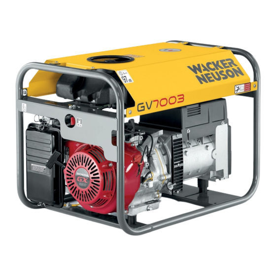
Description and purpose of the machine This machine is a portable power source. The portable generator from Wacker Neuson consists of a steel pipe frame, which includes a fuel tank, a gasoline engine, a control panel and an electrical alternator. The control panel contains controls and bushings. -
Page 10: Operational Safety
3 Safety Regulations Operational safety GEFAHR Carbon monoxide. The application of a generator in buildings can LEAD TO DEATH WITHIN MINUTES. The exhaust fumes from the generator contain carbon monoxide (CO). This is an invisible odorless poison. If the exhaust fumes of the generator can be smelled, CO is being inhaled. Even if no exhaust fumes can be smelled, CO could still be being inhaled. -
Page 11: Operator Qualifications
3 Safety Regulations Connection prerequisites The following prerequisites are to be met to connect the generator to the buil- ding's mains supply. The generator must meet the prerequisites with regard to performance, vol- tage and frequency of the equipment. The generator must be disconnected from the electric power supply. - Page 12 3 Safety Regulations NEVER use generator near open containers of fuel, paint or other flam- mable liquids. NEVER touch the generator or tools connected to it if you have wet hands. NEVER use damaged power cables. Electric shock and major machine ...
- Page 13 3 Safety Regulations Generator vibration Generators vibrate during normal operation. Check during and after use of the generator whether the generator or the extension cord and power cable show da- mage due to vibration. Repair any damage as needed or replace the parts affected. ...
-
Page 14: Safety When Using Combustion Engines
3 Safety Regulations Safety when using combustion engines WARNUNG Combustion engines pose a particular danger during operation and when refue- ling. Failure to follow the warning notices and safety standards can lead to seri- ous injury or death. Read and always observe the warning notices in the operator's manual of the engine and the safety instructions below. -
Page 15: Service Safety
3 Safety Regulations Safety when refueling When refueling the machine: Immediately wipe away any spilled fuel. Fill the fuel tank in a well-ventilated area. Reattach the fuel tank cap after refueling. Do not smoke. Do not refuel hot or running engines. ... - Page 16 king fuel and gases are highly explosive. If spare parts are required for this machine, only use parts from Wacker Neuson or parts that match the original exactly in terms of dimensi- ons, model, intensity and material. 100_0402_si_0003.fm...
-
Page 17: Safety And Information Labels
4 Safety and information labels Safety and information labels There are labels on your equipment that contain important information and safety instructions. Keep all labels legible. Replace missing or illegible labels. The item numbers on the labels can be found in the parts book. Item Label Description... - Page 18 4 Safety and information labels Item Label Description When connecting more than one piece of electronic equipment, special precautions must be taken. Read through the operator's manual. 100_0402_ls_0004.fm...
-
Page 19: Standard Package
5 Standard package Standard package The standard package includes: Equipment. Operator's manual. Parts book. General safety instructions. 100_0402_sd_0001.fm... -
Page 20: Lifting And Transporting
6 Lifting and transporting Lifting and transporting Lifting the machine This compact generator is heavy enough to cause injury in the event of incorrect hoisting technology. Observe the following instructions to lift the generator: Do not try to lift the generator without help. Use suitable lifting bars e. g. ... - Page 21 6 Lifting and transporting 100_0402_tr_0001.fm...
-
Page 22: Operation
2. Check the machine and its components for damage. Do not operate the machine if you find visible damage! Ask the Wacker Neuson dealer for advice at once. 3. Check whether all of the parts belonging to the machine have been delivered and whether all loose parts and fasteners are present. -
Page 23: Power Requirements
Power requirements The Wacker Neuson generator GV 7000A is designed for the operation of single- phase 50 Hz electronic devices for 230 VAC. Generator GV 7003A is designed for the operation of single-phase 50 Hz electronic devices for 230 VAC and/or triple-phase 50 Hz electronic devices for 400 VAC. -
Page 24: Installation
7 Operation Installation Set up the generator so it is protected from rain, snow or other forms of moisture. The ground must be solid and level in order to prevent slipping or displacement. Do not direct the engine exhaust to an area with people. Both the work area as well as the components must be protected from all forms of moisture. - Page 25 7 Operation Outside temperature Devaluation Factor °C 0.97 0.94 0.91 12 % 0.88 High altitude Devaluation Factor 1500 0.97 2000 0.94 2500 0.91 3000 12 % 0.88 3500 15 % 0.85 4000 18 % 0.82 100_0402_op_0003.fm...
-
Page 26: Ground
7 Operation Ground CAUTION Do not The mid-point (neutral) conductor of this equipment is not grounded. drive the PE rod into the ground under normal operating conditions. Refer to the local regulations if the equipment is intended to power a building or similar system. -
Page 27: Use Of Extension Cables
7 Operation Use of extension cables A loss of power takes place when connecting electrical equipment or a tool to the generator with an extension cable — the longer the cable, the greater the loss of power. This means that less voltage is conveyed to the electrical equipment and the power consumption is increased or the performance is reduced. - Page 28 7 Operation Table for extension cable minimum size Extension cable minimum size 230V/1~/50Hz 400V/3~/50Hz Length in m Length in m Ampere- performanc e variable Cross-section surface in mm Diagram for extension cable minimum size 1000 3000 4000 5000 2000 6000 A x m 100_0402_op_0003.fm...
-
Page 29: Control Panel
7 Operation Control Panel See blueprints: wc_gr001275 and wc_gr001369 The fuse protects the generator from significant overloads or short circuits. If the fuse opens, shut down the engine immediately and determine the cause by starting the engine again. Check the electrical equipment and tools connected to the generator and make sure that their power requirements do not exceed the performance limit of the generator or the power limitations of the plug receptacle. - Page 30 7 Operation Description Description Main circuit breaker -10 A,12 A,10 A 3- Schuko IP54 (CEE 7) plug receptacle CEE plug receptacle IP44 2P+E 230 V, 16 A 230 V, 16 A Swiss plug receptacle French plug receptacle 230 V, 16 A 230 V, 16 A CEE plug receptacle IP44 3P+N+E Swiss plug receptacle...
-
Page 31: Before Starting
7 Operation Before starting DANGER Carbon monoxide. The application of a generator in buildings can LEAD TO DEATH WITHIN MINUTES. The exhaust fumes from the generator contain carbon monoxide (CO). This is an invisible odorless poison. If the ex- haust fumes of the generator can be smelled, CO is being inhaled. Even if no exhaust fumes can be smelled, CO could still be being inhaled. -
Page 32: Starting
7 Operation 7.10 Starting See blueprints: wc_gr001299 1. Disconnect all connections from the generator and put the main circuit breaker in an open position (e2). 2. Open fuel shut-off valve (a). Comment: Close the choke (b) if the engine is cold (pull out). Open the choke if the engine is warm (push). -
Page 33: Emergency Stop Procedure
7 Operation 7.12 Emergency stop procedure Procedure In the case of an accident of a failure of the machine during operation, the following procedure is to be applied: 1. Stop the engine. 2. Shut off the fuel supply. 3. Disconnect the tools from the machine. 4. -
Page 34: Maintenance
8 Maintenance Maintenance Period maintenance schedule The following table contains the basic maintenance jobs for the machine. Jobs selected with a check mark can be performed by the operator. The jobs marked with a small box require special training and special equipment. Daily After the Every... -
Page 35: Engine Oil
8 Maintenance Engine oil See blueprint: wc_gr000022 1. Drain the engine oil when the engine is warm. 2. Remove the sealing plug (a) and the drain plug (b) to drain the oil. Comment: For environmental reasons, a bin should be placed under machine to catch the fluid and a waterproof sheet should also be placed under the machine to protect the ground. -
Page 36: Air Cleaner Maintenance
8 Maintenance Air cleaner maintenance See blueprint: wc_gr0001287 This engine is outfitted with a single-element air cleaner. Frequent cleaning of the air cleaner prevents carburetor malfunctions. NOTE: NEVER run the engine without an air cleaner, as this can result in major engine damage. -
Page 37: Spark Plug
8 Maintenance Spark plug See blueprint: wc_gr000028 Clean or replace the spark plug as needed. See engine manual. The exhaust will become very hot during operation and also remains hot for a while after the engine is switched off. Never touch a hot exhaust. WARNING Comment: See the technical data for the recommended spark plug and spark plug air gap. -
Page 38: Engine Speed
8 Maintenance Engine speed See blueprints: wc_gr001300 Generators require a non-adjustable engine speed in order to maintain the correct voltage. The engine speed is controlled by a governor that automatically adjusts to the changing loads of the engine in order to maintain a constant RPM. There is no gas regulator. -
Page 39: Long-Term Storage
8 Maintenance Long-term storage Before long-term storage: 1. Put engine fuel shut-off valve in the closed position. 2. Disconnect fuel line from the carburetor. Place the open end of the line in an appropriate bin and open the fuel shut-off valve to empty the tank. Gasoline is highly flammable. -
Page 40: Basic Troubleshooting
9 Basic troubleshooting Basic troubleshooting Problem / symptom Cause / remedy Check the following if the engine Engine switch is in the "Start" position. does not start: Fuel cock is open. Fuel is replenished. Choke lever is in the correct position. The choke should be ... -
Page 41: 10 Disposal
10 Disposal 10 Disposal 10.1 Disposal of waste electrical and electronic equipment Professional disposal of this machine avoids negative effects on human health and the environment, helps with the targeted treatment of pollutants and makes it possible to recycle valuable raw materials. For customers in EU countries This machine is subject to the European directive for old electrical and electronic equipment (Waste Electrical and Electronic Equipment (WEEE)), as well as the... -
Page 42: 11 Technical Data
11 Technical data 11 Technical data 11.1 GV 7000 Designation Unit GV 7000A GV 7000A GV 7000A Item number 0009348 0009353 5100006205 Peak performance (LTP) Continuous (prime) power output (COP) Net installed power (PRP) Length Width Height Weight Operating weight Generator model NSM K100G NSM K100G... - Page 43 11 Technical data Designation Unit GV 7000A GV 7000A GV 7000A Plug receptacles Quantity Design class Protection rating IP23 IP23 IP23 Operating temperature °C -15 – +40 -15 – +40 -15 – +40 range Max. operating height m NN 1,500 1,500 1,500 Sound pressure level L...
-
Page 44: Gv 7003
11 Technical data 11.2 GV 7003 Designation Unit GV 7003A Item number 5100002155 Peak performance 1~ (LTP) Peak performance 3~(LTP) Continuous (prime) power output 1~(COP) Continuous (prime) power output 3~(COP) Net installed power (PRP) Length Width Height Weight Operating weight... - Page 45 11 Technical data Designation Unit GV 7003A Tank capacity 11.0 Main fuse Available voltages 3~ Available voltages 1~ Plug receptacles CEE 3P 16A 6h 230V 50Hz, CEE 4P 16A 6h 400V 50Hz, Model F: 230V 16A 1~ CEE7/4 Plug receptacles...
-
Page 46: Combustion Engine
11 Technical data 11.3 Combustion engine Designation Manufacturer Honda Type of engine GX390RT2-VPX9-OH Combustion method Four-cycle Cooling Air cooling Cylinders Displacement Max. slanting position ° Fuel type Gasoline Fuel consumption Mixture preparation Carburetor Tank capacity 11.0 Oil specification SAE 10W-40 Max. -
Page 47: 12 Glossary
12 Glossary 12 Glossary Class rating The class rating according to DIN EN 61140 specifies the safety measures for electrical equipment to avoid electrocution. There are four class ratings: Class rating Meaning No special protection apart from the basic insulation. No grounded conductor. - Page 48 12 Glossary Protection class IP The protection class according to DIN EN 60529 indicates the suitability of elec- trical equipment for use in certain ambient conditions as well as the protection against risks. The protection class is specified by an IP code according to DIN EN 60529. Code Meaning 1st number: Protection against touching hazardous parts.
-
Page 49: 13 Diagram
13 Diagram 13 Diagram 13.1 GV 7000A - Wiring diagram Ref. Description Ref. Description Main stator windings Surge absorber Auxiliary winding Circuit breaker Capacitor Plug receptacle 230V, 1Ø, 16 A Rotor windings Plug receptacle 230V, 1Ø, 32 A Diode Color chart Black Purple Orange... -
Page 50: Gv 7003A - Wiring Diagram
13 Diagram 13.2 GV 7003A - Wiring diagram W1V1 U1 ROTOR B W Br L GV 5003A 3~400V/16A 1~230V/16A GV 7003A wc_gr001249 Ref. Description Ref. Description Main stator windings Terminal board Auxiliary winding Circuit breaker Voltage regulator (current rectifier) Plug receptacle 230 V, 1Ø, 16A... -
Page 51: Ec Declaration Of Conformity
EC declaration of conformity Manufacturer Wacker Neuson Produktion GmbH & Co. KG, Preussenstrasse 41, 80809 Munich This declaration of conformity is issued under the sole responsibility of the manufacturer. Product Product GV 7000A GV 7003A Product type Generator Electricity generation...
Need help?
Do you have a question about the GV 7003A and is the answer not in the manual?
Questions and answers