Magnescale LH70 Initial Setup Manual
Hide thumbs
Also See for LH70:
- Quick reference manual (6 pages) ,
- Operation manual (5 pages) ,
- Quick start manual (3 pages)
Table of Contents
Advertisement
Quick Links
LH70
Initial Setup Manual
START
Check the conditions of use
Table of contents
Preparations Before Making The Initial Settings (checking conditions of use)
How To Set Up Detailed Settings (continued from Basic Settings)
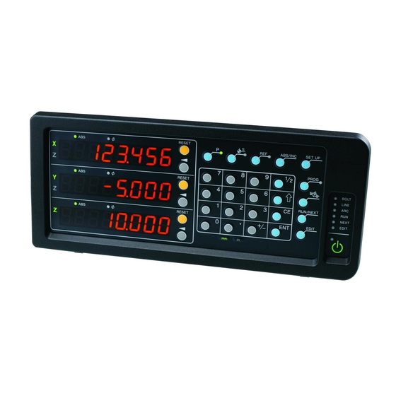
Appendix 1: Front panel, Alarm indication
Appendix 2: Adapter connections (scales and gauges)
Initial Setup Flow
Advance
Preparation
Settings
STEP 1~3
Contents
LH70 initial Setup Manual
Basic
Detailed
Settings
STEP 4~5
STEP 1~3
STEP 4~5
Ver.1 (2020.11) CS&S
LH70
Finished
Page
2 to 3
4 to 6
7
9
10
11 to 12
1/12
Advertisement
Table of Contents

Subscribe to Our Youtube Channel
Related Manuals for Magnescale LH70


Summary of Contents for Magnescale LH70
- Page 1 4 to 6 STEP 1~3 How to set up Detailed Settings (continued from Basic Settings) STEP 4~5 Factory Default (All Clear) Appendix 1: Front panel, Alarm indication Appendix 2: Adapter connections (scales and gauges) 11 to 12 1/12 LH70 initial Setup Manual...
- Page 2 Basic Setting Items Indication Items Description Setting default Type The function of LH70-3 (3 axes) can GENERAL: Milling machine function be selected according to the type of LATHE: Lathe function (function selection) machine used. Only GENERAL (milling machine function) can be selected for LH7-1 / 2 LH70-3 only (1 axis, 2 axes).
- Page 3 Upper:X Axis label switching Display axis label selection Upper axis: "X" or "Z" Middle:Y Middle axis: "Y" or "Z" Can be used with LH70-1 and LH70-2. Error compensation Setting of linear compensation Err OFF:off Lin Err:linear compensation ±600μm/m *Expanded selections ±1000μm/m...
- Page 4 COUNTRY (Destination) Note: When "Lathe" (lathe function) is selected on Symbol Destination Unit the LH70-3 (3-axis input), be sure to connect a scale General area with high resolution to the length measuring unit input axis 2 to display the addition. U.S.A.
- Page 5 1 degree Display method: - For each setting item, the current setting contents are displayed after about 1 second. If 1μm there is no change in the contents, move to the next section with key. 5/12 LH70 initial Setup Manual...
- Page 6 Press key. ⑤ Press key. The display returns to normal. This completes the basic settings. Key to be used at the end of the basic setting mode (LH70) Reset key Φ lamp (two times display) ABS lamp Select axis key...
- Page 7 Note LH70-1, LH70-2 LABEL 2nd axes can be selected from (axis label switching) "X", "Y", and "Z". Note: Can be used with LH70-1 and LH70-2. Error Setting Selection of error compensation function (compensation value) default No compensation Linear compensation Linear Error...
- Page 8 (sleep) none default 5 min. 30 min. 1 min. 10 min. Step 5 6. When the Detailed Settings are complete, switch to the normal display. Press key. This completes the initial settings.. 8/12 LH70 initial Setup Manual...
- Page 9 → → completion 4."RUN" LEDs will be lit. 5. Press key to confirm the number of input axis. In case of LH70-1, is displayed. In case of LH70-2, is displayed. In case of LH70-3, is displayed. 6.Turn off the primary power supply of the AC adapter.
- Page 10 Storage data error Measurement unit not connected Error in reference point Speed over (Note) detection Overflow Power failure Note: When using an adapter connection (SZ**), no speed override indication is shown, but rather an error message. 10/12 LH70 initial Setup Manual...
- Page 11 Scale Resolution Adapter Counter SR-1711(GP)、SR10A/741(GS)、 0.5μm SZ05-T01 LG20 SR50A(GF,GF-R)、SR30A(GM)、 LH70/71/71A/72 SR801/801R(GL) LY71/72 Screws * HA13A, 15A, 23A and 25A are used as head amps SZ05-T01 Head-amp Connector Screws Use screws to secure it in place. 11/12 LH70 initial Setup Manual...
- Page 12 Head-amp Connector Screws Use screws to secure it in place. Gauge Resolution Adapter Counter DE12BR/30BR 0.1μm SZ70-1 LG20 LH70/71/71A/72 Counter unit LY71/72 Cable (300mm) Screws Head-amp Use screws to secure it in place. Connector SZ70-1 12/12 LH70 initial Setup Manual...
Need help?
Do you have a question about the LH70 and is the answer not in the manual?
Questions and answers