
Related Manuals for Aaeon PCM-6892 Rev.B


Summary of Contents for Aaeon PCM-6892 Rev.B
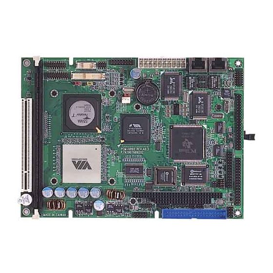
- Page 1 C o m p a c t B o a r d P C M - 6 8 9 2 R e v . B PCM-6892 Rev.B ® ® Intel ULV Celeron 400 / 650 MHz Processor Compact Board With LCD, Ethernet, TV-Out, Mini PCI, Speaker out PCM-6892 Rev.
- Page 2 While reasonable efforts have been made in the preparation of this document to assure its accuracy, AAEON assumes no liabilities resulting from errors or omissions in this document, or from the use of the information contained herein.
- Page 3 C o m p a c t B o a r d P C M - 6 8 9 2 R e v . B Acknowledgments All other product s’ name or trademarks are properties of their respective owners. Award is a trademark of Award Software International, Inc. CompactFlash is a trademark of the Compact Flash Association.
- Page 4 C o m p a c t B o a r d P C M - 6 8 9 2 R e v . B Packing List Before you begin installing your card, please make sure that the following materials have been shipped: •...
-
Page 5: Table Of Contents
C o m p a c t B o a r d P C M - 6 8 9 2 R e v . B Contents Chapter 1 General Information 1.1 Introduction ..................1-2 1.2 Features ..................1-4 1.3 Specifications ................1-5 Chapter 2 Quick Installation Guide 2.1 Safety Precautions ................2-2 2.2 Location of Connectors and Jumpers ........2-3 2.3 Mechanical Drawing..............2-5... - Page 6 C o m p a c t B o a r d P C M - 6 8 9 2 R e v . B 2.18 LAN1 LED Connector (CN8) ..........2-16 2.19 LAN2 LED Connector (CN9) ..........2-17 2.20 Audio Connector (CN10)............2-17 2.21 COM1~4 Connector (CN11) ...........2-18 2.22 USB Connector (CN12) ............2-19 2.23 IrDA Connector (CN14) ............2-19...
- Page 7 C o m p a c t B o a r d P C M - 6 8 9 2 R e v . B Chapter 4 Driver Installation 4.1 Step 1 – Install VIA 4 in 1 Driver ..........4-3 4.2 Step 2 –...
-
Page 8: Chapter 1 General Information
C o m p a c t B o a r d P C M - 6 8 9 2 R e v . B Chapter General Information 1- 1 Chapter 1 General Information... -
Page 9: Introduction
C o m p a c t B o a r d P C M - 6 8 9 2 R e v . B 1.1 Introduction PCM-6892 Rev. B is the extension of PCM-6892 Rev. A. This model possess all features in Rev. A but the only difference Intel Ultra Low ®... - Page 10 C o m p a c t B o a r d P C M - 6 8 9 2 R e v . B expand interface will be the best choice for the embedded application which has the severe condition for the space and environment. 1 - 3 Chapter 1 General Information...
-
Page 11: Features
C o m p a c t B o a r d P C M - 6 8 9 2 R e v . B 1.2 Features • Intel Ultra Low Voltage Celeron 400 / 650 CPU onboard ® • Support 18 / 36 bit TTL/LVDS TFT Panel •... -
Page 12: Specifications
C o m p a c t B o a r d P C M - 6 8 9 2 R e v . B 1.3 Specifications System CPU: Onboard Intel Ultra Low Voltage ® Celeron 400 /650MHz Processor ® Memory: Onboard one 168-pin DIMM socket support up to 512MB SDRAM... - Page 13 C o m p a c t B o a r d P C M - 6 8 9 2 R e v . B A 7(4 x 2-1) pin header support PC/AT keyboard and PS/2 mouse. USB connector: Support four USB 1.1 ports Battery: Lithium battery for data retention Watchdog timer:...
- Page 14 C o m p a c t B o a r d P C M - 6 8 9 2 R e v . B RS-232/422/485 x 1, Parallel x 1 IrDA: One IrDA Tx/Rx header Audio: VIA VT82C686B with AC-97 2.0 compliant audio codec VT1612 USB: Two 5x2 pin headers support 4 USB...
-
Page 15: Chapter 2 Quick Installation Guide
C o m p a c t B o a r d P C M - 6 8 9 2 R e v . B Chapter Quick Installation Guide Notice: The Quick Installation Guide is derived from Chapter 2 of user manual. For other chapters further installation... -
Page 16: Safety Precautions
C o m p a c t B o a r d P C M - 6 8 9 2 R e v . B 2.1 Safety Precautions Always completely disconnect the power cord from your board whenever you are working on it. Do not make connections while the power is on, because a sudden rush of power can damage sensitive electronic components. -
Page 17: Location Of Connectors And Jumpers
C o m p a c t B o a r d P C M - 6 8 9 2 R e v . B 2.2 Location of Connectors and Jumpers Component Side Mini PCI Chapter 2 Quick Installation Guide 2 - 3... - Page 18 C o m p a c t B o a r d P C M - 6 8 9 2 R e v . B Solder Side 2 - 4 Chapter 2 Quick Installation Guide...
-
Page 19: Mechanical Drawing
C o m p a c t B o a r d P C M - 6 8 9 2 R e v . B 2.3 Mechanical Drawing Component Side 2 - 5 Chapter 2 Quick Installation Guide... - Page 20 C o m p a c t B o a r d P C M - 6 8 9 2 R e v . B Solder Side 2 - 6 Chapter 2 Quick Installation Guide...
-
Page 21: List Of Jumpers
C o m p a c t B o a r d P C M - 6 8 9 2 R e v . B 2.4 List of Jumpers There are a number of jumpers in the board that allow you to configure your system to suit your application. -
Page 22: List Of Connectors
C o m p a c t B o a r d P C M - 6 8 9 2 R e v . B 2.5 List of Connectors There are a number of connectors in the board that allow you to configure your system to suit your application. - Page 23 C o m p a c t B o a r d P C M - 6 8 9 2 R e v . B IDE1 EIDE Connector LPT1 LPT Port Connector LAN1 10/100 or 100/1000Base-Tx Ethernet Connector LAN2 10/100 or 100/1000Base-Tx Ethernet Connector PCI1 PCI Slot MPCI1...
-
Page 24: Setting Jumpers
C o m p a c t B o a r d P C M - 6 8 9 2 R e v . B 2.6 Setting Jumpers You configure your card to match the needs of your application by setting jumpers. -
Page 25: Audio Out Selection (Jp1)
C o m p a c t B o a r d P C M - 6 8 9 2 R e v . B 2.7 Audio Out Selection (JP1) J P 1 Function 1-3, 2-4 W/O Amplifier 3-5, 4-6 W/ Amplifier (Default) 2.8 LCD Voltage Selection (JP2) J P 2... -
Page 26: Clear Cmos (Jp4)
C o m p a c t B o a r d P C M - 6 8 9 2 R e v . B 2.10 Clear CMOS (JP 4) Function Protected (Default) Clear 2.11 COM2 Ring/+5V/+12V Selection (JP5) Function +12V Ring (Default) 2.12 TV-Out Connector (CN1) -
Page 27: Ttl_Lcd Connector (Cn2)
C o m p a c t B o a r d P C M - 6 8 9 2 R e v . B 2.13 TTL_LCD Connector (CN2) Signal Signal BLUE10 BLUE11 BLUE12 BLUE13 BLUE14 BLUE15 GREEN10 GREEN11 GREEN12 GREEN13 GREEN14 GREEN15... -
Page 28: Vga Display Connector (Cn4)
C o m p a c t B o a r d P C M - 6 8 9 2 R e v . B 2.14 VGA Display Connector (CN4) Signal Signal VGAVCC GREEN BLUE N.C. N.C. SDATA SCLK N.C. 2.15 ATX Power Connector (CN5) Signal Signal... -
Page 29: Ttl_Lcd Connector (Cn6)
C o m p a c t B o a r d P C M - 6 8 9 2 R e v . B 2.16 TTL_LCD Connector (CN6) Signal Signal +3.3V +3.3V ENBKL BLUE0 BLUE1 BLUE2 BLUE3 BLUE4 BLUE5 BLUE6 BLUE7 GREEN0... -
Page 30: Lvds Connector (Cn7)
C o m p a c t B o a r d P C M - 6 8 9 2 R e v . B 2.17 LVDS Connector (CN7) Signal Signal ENBKL BKLCTL PPVCC LVDS_CH1_TXCLK- LVDS_CH1_TXCLK+ PPVCC LVDS_CH1_TX0- LVDS_CH1_TX0+ LVDS_CH1_TX1- LVDS_CH1_TX1+ LVDS_CH1_TX2- LVDS_CH1_TX2+... -
Page 31: Lan2 Led Connector (Cn9)
C o m p a c t B o a r d P C M - 6 8 9 2 R e v . B 2.19 LAN2 LED Connector (CN9) Signal Signal RX LED +3.3V Link LED +3.3V TX LED +3.3V 2.20 Audio Connector (CN10) Signal... -
Page 32: Com1~4 Connector (Cn11)
C o m p a c t B o a r d P C M - 6 8 9 2 R e v . B 2.21 COM1 4 Connector (CN11) Signal Signal DCD1 DSR1 RXD1 RTS1 TXD1 CTS1 DTR1 COMGND N.C. -
Page 33: Usb Connector (Cn12)
C o m p a c t B o a r d P C M - 6 8 9 2 R e v . B 2.22 USB Connector (CN12) Signal Signal USBD0- USBD0+ USBD1+ USBD1- Signal Signal USBD2- USBD2+ USBD3+ USBD3- 2.23 IrDA Connector (CN14) Signal... -
Page 34: Fan Connector (Cn15)
C o m p a c t B o a r d P C M - 6 8 9 2 R e v . B 2.24 Fan Connector (CN15) Signal Speed Sense 2.25 PS/2 Keyboard & Mouse Connector (CN16) Signal Signal Keyboard DATA Keyboard CLOCK... -
Page 35: Chapter 3 Award Bios Setup
C o m p a c t B o a r d P C M - 6 8 9 2 R e v . B Chapter Award BIOS Setup Chapter 3 Award BIOS Setup... - Page 36 The CMOS memory has lost power and the configuration information has been erased. The PCM-6892 REV.B CMOS memory has an integral lithium battery backup for data retention. However, you will need to replace the complete unit when it finally runs down.
- Page 37 C o m p a c t B o a r d P C M - 6 8 9 2 R e v . B 3.2 Award BIOS Setup Awards BIOS ROM has a built-in Setup program that allows users to modify the basic system configuration.
- Page 38 C o m p a c t B o a r d P C M - 6 8 9 2 R e v . B Integrated Peripherals Use this menu to specify your settings for integrated peripherals. (Primary slave, secondary slave, keyboard, mouse etc.) Power Management Setup Use this menu to specify your settings for power management.
- Page 39 C o m p a c t B o a r d P C M - 6 8 9 2 R e v . B Exit Without Saving Abandon all CMOS value changes and exit setup. 3 - 5 Chapter3 Award BIOS Setup...
-
Page 40: Standard Cmos Features
C o m p a c t B o a r d P C M - 6 8 9 2 R e v . B 3.3 Standard CMOS Features When you choose the Standard CMOS Features option from the INITIAL SETUP SCREEN menu, the s creen shown below is displayed. -
Page 41: Advanced Bios Features
C o m p a c t B o a r d P C M - 6 8 9 2 R e v . B 3.4 Advanced BIOS Features By choosing the Advanced BIOS Features option from the INITIAL SETUP SCREEN menu, the screen below is displayed. This sample screen contains the manufacturer’s default values for the PCM-6892 REV.B 3 - 7... -
Page 42: Advanced Chipset Features
3.5 Advanced Chipset Features By choosing the Advanced Chipset Features option from the INITIAL SETUP SCREEN menu, the screen below is displayed. This sample screen contains the manufacturer’s default values for the PCM-6892 REV.B. 3 - 8 Chapter3 Award BIOS Setup... -
Page 43: Integrated Peripherals
By choosing the Integrated Peripherals from the INITIAL SETUP SCREEN menu, the screen below is displayed. This sample screen contains the manufacturer’s default values for the PCM-6892 REV.B. PCMCIA Card Support Limitation List of PCM -6892 Rev.B COM 3 and 4 need to be disable for supporting 16bit PCMCIA Card under Windows 98 SE... - Page 44 Enable Win XP Disable Remark: *1. "F" means Failed to support. "O" means OK. *2. Special AAEON driver is required for support PCMCIA Card under Windows 98 at ACPI model (see chapter 4) 3 - 10 Chapter3 Award BIOS Setup...
-
Page 45: Power Management Setup
C o m p a c t B o a r d P C M - 6 8 9 2 R e v . B 3.7 Power management Setup By choosing the Power Management Setup from the INITIAL SETUP SCREEN menu, the screen below is displayed. This sample screen contains the manufacturer’s default values for the PCM-6892 REV.B. -
Page 46: Pnp/Pci Configuration
P C M - 6 8 9 2 R e v . B 3.8 PnP/PCI configuration By choosing the PnP/PCI configurations from the Initial Setup Screen menu, the screen below is displayed. This sample screen contains the manufacturer’s default values for the PCM-6892 REV.B. 3 - 12 Chapter3 Award BIOS Setup... -
Page 47: Pc Health Status
3.9 PC Health Status By choosing the PC Health Status from the Initial Setup Screen menu, the screen below is displayed. This sample screen contains the manufacturer’s default values for the PCM-6892 REV.B. 3 - 13 Chapter3 Award BIOS Setup... -
Page 48: Frequency/Voltage Control
P C M - 6 8 9 2 R e v . B 3.10 Frequency/Voltage control By choosing the Frequency/Voltage Control from the Initial Setup Screen menu, the screen below is displayed. This sample screen contains the manufacturer’s default values for the PCM-6892 REV.B. 3 - 14 Chapter3 Award BIOS Setup... -
Page 49: Load Fail-Safe Defaults
C o m p a c t B o a r d P C M - 6 8 9 2 R e v . B 3.11 Load Fail-Safe Defaults When you press <Enter> on this item you get a confirmation dialog box with a message similar to: Load Fail-Safe Default (Y/N)? Pressing "Y"... -
Page 50: Load Optimized Defaults
C o m p a c t B o a r d P C M - 6 8 9 2 R e v . B 3.12 Load Optimized Defaults When you press <Enter> on this item you get a confirmation dialog box with a message similar to: Load Optimized Defaults (Y/N)? Pressing "Y"... -
Page 51: Set Supervisor/User Password
C o m p a c t B o a r d P C M - 6 8 9 2 R e v . B 3.13 Set Supervisor/User Password You can set either SUPERVISOR or USER PASSWORD, or both of them. -
Page 52: Save & Exit Setup
C o m p a c t B o a r d P C M - 6 8 9 2 R e v . B 3.14 Save & Exit Setup If you select this option and press <Enter>, the values entered in the setup utilities will be recorded in the chipset’s CMOS memory. -
Page 53: Exit Without Saving
C o m p a c t B o a r d P C M - 6 8 9 2 R e v . B 3.15 Exit without saving Selecting this option and pressing <Enter> allows you to exit the Setup program without recording any new value or changing old one. -
Page 54: Chapter 4 Driver Installation
C o m p a c t B o a r d P C M - 6 8 9 2 R e v . B Chapter Driver Installation Chapter 4 Driver Installation... -
Page 55: Step 1 - Install Via 4 In 1 Driver
C o m p a c t B o a r d P C M - 6 8 9 2 R e v . B The PCM-6892 Rev.B comes with a CD-ROM that contains all drivers and utilities that you need for setup the system. - Page 56 C o m p a c t B o a r d P C M - 6 8 9 2 R e v . B 4.1 Step 1 – Install VIA 4 in 1 for Windows 98SE/2000/XP 1. Double click on the “.exe” file. 2.
- Page 57 2. Follow the instructions that the window will show you. 3. The system will help you install the driver automatically. 4.5 Step 5 – Install AAEON PCMCIA Driver for Windows 98SE 1. Double click on the “TiSetup.exe” file. 2. Follow the instructions that the window will show you.
-
Page 58: Appendix A I/O Information
C o m p a c t B o a r d P C M - 6 8 9 2 R e v . B Appendix I/O Information Appendix A I/O Information... -
Page 59: I/O Address Map
C o m p a c t B o a r d P C M - 6 8 9 2 R e v . B A.1 I/O Address Map Address Description User Address 000-01F DMA Controller #1 000-000F 020-03F Interrupt Controller #1, Master 020-021 040-05F System Time... -
Page 60: Irq Mapping Chart
C o m p a c t B o a r d P C M - 6 8 9 2 R e v . B A.3 IRQ Mapping Chart IRQ0 System Timer IRQ8 System CMOS / Real time clock IRQ1 Keyboard IRQ9 Microsoft ACPI –... -
Page 61: Appendix B Programming The Watchdog Timer
C o m p a c t B o a r d P C M - 6 8 9 2 R e v . B Appendix Programming the Watchdog Timer Appendix B Programming the Watchdog Timer... -
Page 62: Programming The Watchdog Timer
C o m p a c t B o a r d P C M - 6 8 9 2 R e v . B B.1 Programming the Watchdog Timer PCM-6892 contains a watchdog timer reset pin. (GP16) All reference material can be found on the following pages. Appendix B Programming the Watchdog Timer... - Page 63 P C M - 6 8 9 2 R e v . B ==================================================** ** Title : WatchDog Timer Setup Utility (for W83977 GP16) ** ** Company : AAEON Technology Inc. ** ** Compiler : Borland C ++ Version 3.0 ** **=================================================== ===========*/ #include <dos.h>...
- Page 64 C o m p a c t B o a r d P C M - 6 8 9 2 R e v . B void ExitConfigMode() outportb(IO_INDEX_PORT, LOCK_DATA); void SelectDevice(unsigned char device) outportb(IO_INDEX_PORT, DEVICE_REGISTER); outportb(IO_DATA_PORT, device); unsigned char ReadAData(short int reg) outportb(IO_INDEX_PORT, reg);...
- Page 65 C o m p a c t B o a r d P C M - 6 8 9 2 R e v . B WriteAData(0xF2, time_val); // set counter counts in second (or minute) // Register F4 Bit 6 = 0/1 (minutes/seconds) // For w83977EF only WriteAData(0xF4, 0x40);...
- Page 66 C o m p a c t B o a r d P C M - 6 8 9 2 R e v . B WriteAData(0xE3, 0x0A); else if(watch_dog_output_GP==16) //Set Register E6 to define GP16 WriteAData(0xE6, 0x0A); //Select Device 8 SelectDevice(8);...
- Page 67 *ptr; printf( inBond 83977 WatchDog Timer Setup Utility w Version 1.0 \n" ); printf( copyright (c) 2000 AAEON Technology Inc.\n");C printf( this version only for W83977 that using GP%d to T Reset System.\n",watch_dog_output_GP); if (argc == 1) printf( n Syntax: WATCHDOG [time] \n"...
- Page 68 C o m p a c t B o a r d P C M - 6 8 9 2 R e v . B if (argc > 1) ptr = argv[1]; time_value = atoi(ptr); if (time_value > 0 && time_value < 256) SetWatchDogTime((unsigned char) time_value);...
Need help?
Do you have a question about the PCM-6892 Rev.B and is the answer not in the manual?
Questions and answers