Table of Contents
Advertisement
Quick Links
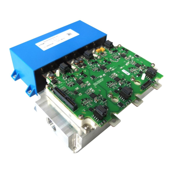
AN-HPDKIT-SiC-G1-GATEDRIVE
User Manual for HPD GD BOARD G1 SiC
Gate Driver Board
About this document
Scope and purpose
This application note describes the features of and how to operate the evaluation gate driver board
HPD GD BOARD G1 SiC for HybridPACK™ Drive CoolSiC™ modules.
Intended audience
Experienced engineers designing gate drive boards for HybridPACK™ Drive CoolSiC™ modules.
Evaluation Board
This board is to be used during the design-in process for evaluating and measuring characteristic curves, and
for checking datasheet specifications.
The evaluation gate driver board was designed to support customers during their first steps in designing
applications with the HybridPACK™ Drive power module and gate driver EiceDRIVER
. An evaluation board is
TM
not intended to be an optimal design for every specific requirement. But it gives a good starting point and
useful design hints for serial development. Furthermore, practical experience from the power module switching
characteristic as well as the gate driver features can be obtained in the lab at a minimum effort by using such
evaluation tools.
Note:
PCB and auxiliary circuits are NOT optimized for final customer design.
Application Note
Please read the Important Notice, the Safety precautions and the Warnings
<Revision 1.0>
www.infineon.com
<2022-05-27>
Advertisement
Table of Contents

Subscribe to Our Youtube Channel
Related Manuals for Infineon HPD GD BOARD G1 SiC


Summary of Contents for Infineon HPD GD BOARD G1 SiC
- Page 1 Scope and purpose This application note describes the features of and how to operate the evaluation gate driver board HPD GD BOARD G1 SiC for HybridPACK™ Drive CoolSiC™ modules. Intended audience Experienced engineers designing gate drive boards for HybridPACK™ Drive CoolSiC™ modules.
-
Page 2: Important Notice
Boards provided by Infineon Technologies. The design of the Evaluation Boards and Reference Boards has been tested by Infineon Technologies only as described in this document. The design is not qualified in terms of safety requirements, manufacturing and operation over the entire operating temperature range or lifetime. -
Page 3: Safety Precautions
User Manual for HPD GD BOARD G1 SiC Gate Driver Board Safety precautions Safety precautions Note: Please note the following warnings regarding the hazards associated with development systems. Table 1 Safety precautions Warning: The DC link potential of this board is up to 500 VDC. When measuring voltage waveforms by oscilloscope, high voltage differential probes must be used. -
Page 4: Table Of Contents
Important notice ..........................2 Safety precautions .......................... 3 Table of Contents ........................... 4 How to order Gate Driver Boards (HPD GD BOARD G1 SiC) ........... 5 Feature and Limitations Overview ................... 6 Block Diagram & Key Features ........................ 6 Recommended Operating Conditions ....................7 Limitations of the Evaluation Kit ...................... -
Page 5: How To Order Gate Driver Boards (Hpd Gd Board G1 Sic)
How to order Gate Driver Boards (HPD GD BOARD G1 SiC) How to order Gate Driver Boards (HPD GD BOARD G1 SiC) The evaluation gate driver board HPD GD BOARD G1 SiC, compatible for HybridPACK™ Drive CoolSiC™ 1200V SiC modules FS0xMR12A6MA1x, can be ordered via Infineon Sales Partners: ... -
Page 6: Feature And Limitations Overview
Feature and Limitations Overview Feature and Limitations Overview The evaluation gate driver board HPD GD BOARD G1 SiC is an isolated six-channel gate driver board dedicated for the evaluation purpose of HybridPACK™ Drive CoolSiC™ modules. It comes with Infineon automotive EiceDRIVER gate driver ICs. -
Page 7: Recommended Operating Conditions
On the other hand, the evaluation gate driver board together with the power module should not be regarded as a protected system. It is not a considered product for end customers. The evaluation gate driver board is to support engineers in their first steps designing with the Infineon EiceDRIVER and HybridPACK... -
Page 8: Key Components List
User Manual for HPD GD BOARD G1 SiC Gate Driver Board Feature and Limitations Overview Key Components List Some key components can be found in Table 3. The gate driver board uses more active and passive components which are not listed here. -
Page 9: Quickstart Guide
Signal Connector X1 & Interface PCB The evaluation gate driver board is equipped with a Samtec board to board connector. It is compatible with the Infineon Aurix Microcontroller logic board, which is used for all HybridKits. The small interface PCB is designed as 1:1 connector. - Page 10 User Manual for HPD GD BOARD G1 SiC Gate Driver Board Quickstart Guide Figure 5 The test pad areas indicated on the gate driver board (a). See Table 4 for a description. Important test pads are positioned also at the side of the signal connector (b).
- Page 11 User Manual for HPD GD BOARD G1 SiC Gate Driver Board Quickstart Guide phase U low-side (HS_U): PWM_HS_U PWM input Data_dT1 Data signal phase V low-side (HS_V): PWM_HS_V PWM input Data_dT3 Data signal phase W low-side (HS_W): PWM_HS_W PWM input...
-
Page 12: Power Supply To The Gate Driver Board
User Manual for HPD GD BOARD G1 SiC Gate Driver Board Quickstart Guide Power Supply to the Gate Driver Board The gate driver board requires a DC voltage supply between 8V and 18V for the operation. For a long testing time, a DC voltage at about 14V is recommended. -
Page 13: Double Pulse Test (Without A Mcu Board)
User Manual for HPD GD BOARD G1 SiC Gate Driver Board Quickstart Guide Double Pulse Test (without a MCU board) 3.4.1 Enabling gate driver EiceDRIVER The evaluation gate driver board is designed with the new automotive gate driver EiceDRIVER 1EDI3033AS. For first evaluation tests, like the double pulse test, it is possible to operate the gate driver board without a MCU board. -
Page 14: Switching The Gate Driver
User Manual for HPD GD BOARD G1 SiC Gate Driver Board Quickstart Guide 3.4.2 Switching the gate driver After the EiceD3RIVER is enabled (section 3.4.1), it is ready to switch the EiceDRIVER with e.g. a pulse generator. Now the gate can be controlled by the PWM signal: ... -
Page 15: Monitoring Feature
User Manual for HPD GD BOARD G1 SiC Gate Driver Board Quickstart Guide Monitoring feature 3.5.1 LED diagnosis This gate driver board integrated 15 LEDs providing some diagnosis information of the board. These LEDs are located across the whole board, each with a marking. If an LED is on, it indicates the corresponding function or feature is in order. -
Page 16: Fault Signal Nflt And Ready Signal Rdy
User Manual for HPD GD BOARD G1 SiC Gate Driver Board Quickstart Guide 3.5.3 Fault signal NFLT and ready signal RDY Fault signal NFLT and ready signal RDY of a gate driver IC are connected, generating a logic “AND” signal as shown in Figure 10. -
Page 17: Ntc Temperature And Dc-Link Voltage Measurement
User Manual for HPD GD BOARD G1 SiC Gate Driver Board Quickstart Guide NTC temperature and DC-Link voltage Measurement The gate driver EiceDRIVER has an ADC to measure DC-Link voltage or NTC temperature. The gate driver board has in total six EiceDRIVER ICs. -
Page 18: Dc-Link Voltage Measurement
User Manual for HPD GD BOARD G1 SiC Gate Driver Board Quickstart Guide the NTC which has to be isolated from the microcontroller for safety reasons. Digital signals are much easier to transfer via galvanic isolated barriers compared to analog signals. -
Page 19: References And Revision History
Infineon Application Note AN-HPDPERF-ASSEMBLY, “Assembly Instructions for the HybridPACK Drive Performance”. Infineon Application Note AN-HPDKIT-QUICKSTART, “HybridKit Drive Quickstart Guide”. Infineon Application Note AN-HPDKIT-ADVANCED-FEATURES, “HybridKit Drive Advanced Features”. Infineon Application Note AN-HPDKIT-GATEDRIVE, “HybridKit Evaluation Gate Driver Board for 1200V IGBT4”. Infineon Application Note Z8F80039908, “EiceDRIVER 1EDI302xAS/ EiceDRIVER 1EDI303xAS”. Revision History... - Page 20 WARNINGS Due to technical requirements products may contain © 2022 Infineon Technologies AG. dangerous substances. For information on the types in question please contact your nearest Infineon All Rights Reserved. Technologies office. Do you have a question about this Except as otherwise explicitly approved by Infineon...
Need help?
Do you have a question about the HPD GD BOARD G1 SiC and is the answer not in the manual?
Questions and answers