Sign In
Upload
Manuals
Brands
iWave Manuals
Single board computers
i.MX 8M Mini
iWave i.MX 8M Mini Manuals
Manuals and User Guides for iWave i.MX 8M Mini. We have
5
iWave i.MX 8M Mini manuals available for free PDF download: Hardware User's Manual, Quick Start Manual
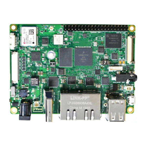
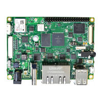
iWave i.MX 8M Mini Hardware User's Manual (66 pages)
Pico ITX Single Board Computer
Brand:
iWave
| Category:
Single board computers
| Size: 7 MB
Table of Contents
Table of Contents
4
Introduction
8
Purpose
8
Pico Itx Sbc Overview
8
List of Acronyms
8
Table 1: Acronyms & Abbreviations
8
Terminology Description
10
References
10
Table 2: Terminology
10
Important Note
11
Architecture and Design
12
I.MX 8M Mini or I.MX 8M Nano Pico ITX Block Diagram
12
Figure 1 : I.MX 8M Mini or I.MX 8M Nano Pico ITX SBC Block Diagram
12
I.MX 8M Mini or I.MX 8M Nano Pico ITX SBC Features
13
Cpu
16
I.MX 8M Mini CPU
16
Figure 2: I.MX 8M Mini Block Diagram
16
I.MX 8M Nano Soc
17
Figure 3: I.MX 8Mnano Block Diagram
17
Pmic
18
Memory
19
Lpddr4 Ram
19
Emmc Flash
19
Micro SD Connector
19
Figure 4: Micro SD Card Connector
19
Rtc Controller
20
Boot Media Setting
21
Figure 5: Boot Media Switch
21
Table 3: Boot Media Switch Settings
21
Table 4: Boot Mode Pin Settings Truth Table
21
Network & Communication
22
Wi-Fi and Bluetooth Interface
22
Figure 6: Wi-Fi and Bluetooth Antenna Connector
22
Gigabit Ethernet Interface
23
USB2.0 Host Interface
24
Figure 7: Dual RJ45 Magjack
24
USB2.0 OTG Interface
25
Figure 8: Dual Stack USB2.0 Type a Connector
25
GNSS Module (Optional)
26
CAN Interface
26
Figure 9: USB OTG Connector
26
Figure 10: CAN Connector
27
Table 5: CAN Header Pinout
27
Serial Interface Features
28
Debug UART Interface
28
Figure 11: Debug UART Header (Optional)
28
Table 6: Debug UART Header Pinout
28
RS232 Data UART Interface (Optional)
29
Figure 12: Debug UART through Expansion Connector
29
Table 7: Debug UART through Expansion Connector Pinout
29
RS485 Data UART Interface
30
Figure 13: RS232 Header
30
Table 8: RS232 Data UART Header Pinout
30
Figure 14: RS485 Header
31
Table 9: RS485 Data UART Header Pinout
31
Audio/Video Features
32
MIPI CSI Connector
32
Figure 15: 36 Pin MIPI CSI Connector
32
Table 10: MIPI CSI Connector Pinouts
32
I2S Audio Interface
34
Audio Amplifier
34
Figure 16: Audio IN/OUT Jack
34
HDMI/LVDS Display Interface
35
Figure 17: Speaker Header
35
Table 11: Speaker Header Pinout
35
Figure 18: HDMI out Connector
36
Figure 19: 40 Pin LVDS Display Connector
37
Table 12: 40 Pin 10.1" LVDS Display Pinout
37
USB Touch Connector
38
Figure 20: USB Touch Connector
38
MIPI DSI Display (Optional)
39
Figure 21: MIPI DSI Connector
39
Table 13: LVDS Display Touch Pinouts
39
Table 14: MIPI DSI Connector Pinouts
40
Keyb Connector
41
Figure 22: M.2 Key B Connector
41
Figure 23: Nano SIM Connector
42
Table 15: M.2 Connector Pinout
42
Figure 24: M.2 Module Insertion Guide
45
Expansion Connector
46
Figure 25: Expansion Connector
46
Table 16: Expansion Connector Pinouts
46
Other Features
49
Fan Header
49
RTC Controller with RTC Battery Header
49
Figure 26: Fan Connector
49
Table 17: Fan Connector Pin Assignment
49
JTAG Interface
50
Figure 27: RTC Battery Connector
50
Table 18: RTC Battery Header Pin Assignment
50
Figure 28: JTAG Header
51
Table 19: JTAG Header Pin Assignment
51
Power ON/OFF Switch
52
Reset Switch
52
Figure 29: Power ON/OFF Switch
52
CPU ON/OFF Switch
53
Figure 30: Reset Switch
53
Figure 31: CPU ON/OFF Switch
53
I.MX 8M Mini Pin Multiplexing on Expansion Connector
54
Table 20: I.MX 8M Mini CPU IOMUX for Expansion Connector Interfaces
54
I.MX 8M Nano Pin Multiplexing on Expansion Connector
56
Table 21: I.MX 8M Nano CPU IOMUX for Expansion Connector Interfaces
56
Technical Specification
57
Electrical Characteristics
57
Power Input Requirement
57
Figure 32: Power Input Jack
57
Table 22: Power Input Requirement
58
Power Consumption
59
Table23: I.MX 8M Mini Pico ITX SBC Power Consumption
59
Table24: I.MX 8M Nano Pico ITX SBC Power Consumption
59
Environmentalcharacteristics
61
Environmental Specification
61
Heat Sink
61
Table 25: Environmental Specification
61
Rohs Compliance
62
Electrostatic Discharge
62
Figure 33: Mechanical Dimension of Heat Sink
62
Mechanical Characteristics
63
I.MX 8M Mini or I.MX 8M Nano Pico ITX SBC Mechanical Dimensions
63
Figure 34: Mechanical Dimensions of 1.MX 8M Mini or I.MX 8M Nano Pico ITX SBC Top View
63
Figure 35: Mechanical Dimensions of 1.MX 8M Mini or I.MX 8M Nano Pico ITX SBC Side View-1
63
Figure 36: Mechanical Dimensions of 1.MX 8M Mini or I.MX 8M Nano Pico ITX SBC Bottom View
64
Figure 37: Mechanical Dimensions of 1.MX 8M Mini or I.MX 8M Nano Pico ITX SBC Side View-2
64
Ordering Information
65
Table 26: Orderable Product Part Numbers
65
Iwave Systems Technologies Pvt. Ltd
66
Advertisement
iWave i.MX 8M Mini Hardware User's Manual (73 pages)
Brand:
iWave
| Category:
Microcontrollers
| Size: 6 MB
Table of Contents
Table of Contents
4
Introduction
8
Purpose
8
Overview
8
List of Acronyms
8
Table 1: Acronyms & Abbreviations
8
Terminlogy Description
10
References
10
Table 2: Terminology
10
Architecture and Design - Qseven Carrier Board
11
I.MX 8M Mini or I.MX 8M Nano Qseven Carrier Board Block Diagram
11
Figure 1: I.MX 8M Mini or I.MX 8M Nano Qseven Development Platform Block Diagram
11
I.MX 8M Mini or I.MX 8M Nano Qseven Development Platform Features
12
Qseven MXM Connector
14
Figure 2: Qseven MXM Connector
14
Table 3: Qseven MXM Connector Pin out
15
Figure 14: Sd/MMC Connector
18
On Board Switches
33
Power ON/OFF Switch
33
Figure 3: Power On/Off Switch
33
Board Configuration Switch
34
Figure 4: Board Configuration Switch
34
General Purpose Berg-Stick
35
Figure 5: General Purpose Berg-Stick
35
Table 4: Board Configuration Switch
35
Reset Switch
36
Figure 6: Reset Switch
36
Table 5: General Purpose 6 Pin Berg-Stick
36
Serial Interface Features
37
Debug UART Port
37
Figure 7: Debug Uart
37
Data UART Header
38
Figure 8: Data Uart Header
38
Table 6: Data Uart Header Pin out
38
High Speed Interface Features
39
Key-B Connector-1
39
Figure 9: M.2 Key-B Connector-1
39
Table 7: M.2 Key-B Connector-1 Pinout
39
Key-B/Key-M Connector-2
42
Figure 10: M.2 Key-B/Key-M Connector
43
Table 8: M.2 Key-B/Key-M Connector Pin out
43
Note: Pcie Is Not Supported in I.MX 8M Nano Soc
46
Communication Interface Features
47
Gigabit Ethernet Port
47
USB2.0 Ports (Host)
47
Figure 11: Rj45 Magjack
47
USB2.0 Port1 (OTG)
48
Figure 12: USB2.0 Port (Host)
48
SDIO Port
49
Figure 13: Usb2.0 Port (Otg)
49
CAN Header
51
Table 9: Can Header Pin out
51
Audio/Video Features
52
Audio IN&OUT
52
Figure 16: Audio In/Outj Ack
52
7" LCD with Capacitive Touch
53
Figure 17: Rgb Lcd Connector
53
Table 10: 7" Rgb Lcd Connector Pin out
53
HDMI Port
55
Figure 18: Capacitive Touch Connector
55
Table 11: Capacitive Touch Connector Pin out
55
Figure 19: Hdmi Connector
56
Additional Features
57
SPI Flash
57
RTC Coin Cell Holder
57
Figure 20: Coin Cell Holder
57
Fan Header
58
Figure 21: Fan Header
58
Table 12: Fan Header Pin out
58
JTAG Header (Optional)
59
Figure 22: Jtag Header
59
Table 13: Jtag Header Pin out
60
Carrier Board Expansion Connectors
61
Figure 23: Carrier Board Expansion Connectors
61
Carrier Board Power & Io Headers
62
Figure 24: Carrier Board Power & Io Headers
62
Table 14: Carrier Board Power & IO Header-1
62
Table 15: Carrier Board Power & IO Header-2
63
Table 16: Carrier Board Power Header
64
Technical Specification
65
Electrical Characteristics
65
Power Input Requirement
65
Figure 25: Power Jack
65
Table 17: Power Jack Pin out
65
Power Output Specification
66
Table 18: Power Input Requirement
66
Table 19: Power Output Specification
66
Environmental Characteristics
67
Environmental Specification
67
Rohs Compliance
67
Electrostatic Discharge
67
Table 20: Environmental Specification
67
Mechanical Characteristics
68
I.MX 8M Mini or I.MX 8M Nano Qseven Carrier Board Mechanical Dimensions
68
Figure 26: I.MX 8M Mini or I.MX 8M Nano Qseven Carrier Board Mechanical Dimension - Top View
68
Figure 27: I.MX 8M Mini or I.MX 8M Nano Qseven Carrier Board Mechanical Dimension - Bottom View
69
Figure 28: I.MX 8M Mini or I.MX 8M Nano Qseven Carrier Board Mechanical Dimension - Top Max Heighted
69
Guidelines to Insert the Μqseven SOM into Carrier Board
70
Figure 29: I.MX 8M Mini or I.MX 8M Nano Qseven Carrier Board Mechanical Dimension - Bottom Max Heighted
70
Figure 30: Μqseven SOM Insertion Step -1
70
Figure 31: Μqseven SOM Insertion Step -2
71
Figure 32: Μqseven SOM Insertion Step -3
71
Figure 33: Μqseven SOM Insertion Step -4
71
Ordering Information
72
Table 21: Orderable Product Part Numbers
72
iWave i.MX 8M Mini Hardware User's Manual (60 pages)
iW-RainboW-G34S/G37S Pico ITX Single Board Computer
Brand:
iWave
| Category:
Single board computers
| Size: 7 MB
Table of Contents
Table of Contents
4
Introduction
8
Purpose
8
Pico ITX SBC Overview
8
List of Acronyms
8
Table 1: Acronyms & Abbreviations
8
Terminology Description
10
References
10
Table 2: Terminology
10
Important Note
11
Architecture and Design
12
I.MX 8M Mini or I.MX 8M Nano Pico ITX SBC Block Diagram
12
Figure 1: I.MX 8M Mini or I.MX 8M Nano Pico ITX SBC Block Diagram
12
I.MX 8M Mini or I.MX 8M Nano Pico ITX SBC Features
13
Cpu
16
I.MX 8M Mini CPU
16
Figure 2: I.MX 8M Mini Block Diagram
16
I.MX 8M Nano Soc
17
Figure 3: I.MX 8M Nano Block Diagram
17
Pmic
18
Memory
19
Lpddr4 Ram
19
Emmc Flash
19
Micro SD Connector
19
Figure 4: Micro SD Card Connector
19
Boot Media Setting
20
Figure 5: Boot Media Switch
20
Table 3: Boot Media Settings
20
Network & Communication
21
Wi-Fi and Bluetooth Interface
21
Figure 6: Wi-Fi and Bluetooth Antenna Connector
21
Gigabit Ethernet Interface
22
Figure 7: Dual RJ45 Magjack
23
USB2.0 Host Interface
24
Figure 8: Dual Stack USB2.0 Type a Connector
24
USB2.0 OTG Interface
25
GNSS Module
25
Figure 9: USB OTG Connector
25
CAN Interface
26
Figure 10: GNSS Antenna Connector
26
Serial Interface Features
27
Debug UART Interface
27
Figure 11: CAN Connector
27
Table 4: CAN Header Pinout
27
Figure 12: Debug UART Header (Optional)
28
Table 5: Debug UART Header Pinout
28
RS232 Data UART Interface
29
Figure 13: Debug UART through Expansion Connector
29
Table 6: Debug UART through Expansion Connector Pinout
29
RS485 Data UART Interface (Optional)
30
Figure 14: RS232 Header
30
Table 7: RS232 Data UART Header Pinout
30
Audio/Video Features
31
MIPI CSI Connector
31
Figure 15: RS485 Header
31
Table 8: RS485 Data UART Header Pinout
31
Figure 16: 36 Pin MIPI CSI Connector
32
Table 9: MIPI Csi Connector Pinouts
32
I2S Audio Interface
33
Figure 17: Audio IN/OUT Jack
34
Figure 18: Speaker Header
34
HDMI & LVDS Display Interface
35
Figure 19: HDMI out Connector
35
Table 10: Speaker Header Pinout
35
Figure 20: 40 Pin LVDS Display Connector
36
Table 11: 40 Pin 10.1" LVDS Display Pinout
36
USB Touch Connector
37
Figure 21: USB Touch Connector
37
MIPI DSI Display (Optional)
38
Figure 22: MIPI DSI Connector
38
Table 12: LVDS Display Touch Pinouts
38
Key B Connector
39
Table 13: MIPI DSI Connector Pinouts
39
Figure 23: M.2 Key B Connector
40
Figure 24: Nano SIM Connector
40
Expansion Connector
41
Figure 25: Expansion Connector
41
Table 14: Expansion Connector Pinouts
41
Other Features
43
Fan Header
43
Figure 26: Fan Connector
43
RTC Controller with RTC Battery Header
44
Figure 27: RTC Battery Connector
44
Table 15: Fan Connector Pin Assignment
44
JTAG Interface
45
Figure 28: JTAG Header
45
Table 16: RTC Battery Header Pin Assignment
45
Power ON/OFF Switch
46
Table 17: JTAG Header Pin Assignment
46
Reset Switch
47
Figure 29: Power ON/OFF Switch
47
Figure 30: Reset Switch
47
CPU ON/OFF Switch
48
Figure 31: CPU ON/OFF Switch
48
I.MX 8M Mini Pin Multiplexing on Expansion Connector
49
Table 18: I.MX 8M Mini CPU IOMUX for Expansion Connector Interfaces
49
I.MX 8M Nano Pin Multiplexing on Expansion Connector
51
Table 19: I.MX 8Mnano CPU IOMUX for Expansion Connector Interfaces
51
Technical Specification
53
Electrical Characteristics
53
Power Input Requirement
53
Figure 32: Power Input Jack
53
Power Consumption
54
Table 20: Power Input Requirement
54
Table21: I.MX 8M Mini Pico ITX SBC Power Consumption
54
Table22: I.MX 8M Nano Pico ITX SBC Power Consumption
55
Environmental Characteristics
56
Environmental Specification
56
Heat Sink & Fan Sink
56
Table 23: Environmental Specification
56
Rohs Compliance
57
Electrostatic Discharge
57
Mechanical Characteristics
58
I.MX 8M Mini or I.MX 8M Nano Pico ITX SBC Mechanical Dimensions
58
Ordering Information
59
Table 24: Orderable Product Part Numbers
59
Advertisement
iWave i.MX 8M Mini Hardware User's Manual (62 pages)
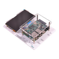
i.MX 8M Mini or i.MX 8M Nano SODIMM Development Platform
Brand:
iWave
| Category:
Motherboard
| Size: 5 MB
Table of Contents
Table of Contents
4
1 Introduction
8
Purpose
8
Overview
8
List of Acronyms
8
Table 1: Acronyms & Abbreviations
8
Terminlogy Description
10
References
10
Table 2: Terminology
10
2 Architecture and Design-Sodimm Carrier Board
11
I.MX 8M Mini or I.MX 8M Nano SODIMM Development Platform Block Diagram
11
Figure 1: I.MX 8M Mini or I.MX 8M Nano SODIMM SOM Development Platform Block Diagram
11
I.MX 8M Mini or I.MX 8M Nano SODIMM Development Platform Features
12
SODIMM Edge Connector
14
Figure 2: SODIMM Connector
14
Table 3: 200-Pin PCB Edge Connector Pin Assignment
15
Serial Interface Features
26
Debug UART
26
Figure 3: Debug UART
26
Table 4: Debug UART Connector Pin out
26
Data UART Header
27
Figure 4: Data UART Header
27
Table 5: Data UART Header Pin out
27
Communication Features
28
10/100/1000Mbps Ethernet -1
28
Figure 5: 10/100/1000Mbps RJ45 Magjack -1
28
10/100/1000 Mbps Ethernet-2 (Optional) (Not Available in Nano)
29
Figure 6: 10/100/1000Mbps RJ45 Magjack-2
29
USB2.0 Device
30
Figure 7: USB2.0 Device Port
30
USB2.0 Host (Not Available in Nano)
31
Figure 8: USB 2.0 Host Ports
31
Microsd Slot
32
Figure 9: Micro SD Connector
32
High Speed Interfaces
33
Mini Pcie Port
33
Figure 10: Mini Pcie Slot
33
Table 6: Mini Pcie Slot Pinout
33
Audio/Video Features
36
Audio IN/OUT Jack
36
Figure 11: Audio IN/OUT Jack
36
Table 7: Audio In/Out Jack Pin out
36
Additional Features
37
MIPI CSI Camera Connector
37
Figure 12: MIPI CSI Camera FPC Connector
37
Table 8: 40 Pin -MIPI CSI Camera FPC Connector
38
MIPI DSI Display Interface Connector
39
Figure 13: MIPI DSI Display Interface Connector
39
Table 9: 20 Pin -MIPI DSI Connector Pin out
40
Boot Mode Switch
41
Figure 14: Boot Switch
41
Table 10: I.MX 8M Mini Boot Mode Settings
41
Reset Switch
42
Figure 15: Reset Switch
42
Table 11: I.MX 8M Nano Boot Mode Settings
42
Power On/Off Switch
43
JTAG Header
43
Figure 16: Power On/Off Switch
43
Figure 17: JTAG Header
44
Table 12: JTAG Header
44
RTC Coin Cell Holder
45
Expansion Header
45
Figure 18: RTC Coin Cell Holder
45
Table 13: RTC Coin Cell Holder Pin out
45
Figure 19: Expansion Header
46
Table 14: Expansion Header Pin out
46
GPIO Header
47
Figure 20: GPIO Header
47
Table 15: GPIO Header Pin out
48
3 Architecture and Design-Sodimm Mipi Daughter Board
49
I.MX 8M Mini or I.MX 8M Nano SODIMM MIPI Daughter Board Block Diagram
49
Figure 21: SODIMM MIPI Daughter Board Block Diagram
49
SODIMM MIPI Daughter Board Features
50
Figure 22: SODIMM MIPI Daughter Board MIPI Connectors
50
Video Features
51
MIPI DSI Display
51
Figure 23: MIPI DSI Display Connector
51
Table 16: MIPI Display Connector Pinout
51
MIPI CSI Camera
53
Figure 24: MIPI Camera Connector
53
Table 17: MIPI Camera Connector Pin out
53
4 Technical Specification
55
Electrical Characteristics
55
Power Input Requirement
55
Figure 25: Power Jack
55
Table 18: Power Jack Pin out
55
Table 19: Power Input Requirement
56
Environmental Characteristics
57
Environmental Specification
57
Rohs Compliance
57
Electrostatic Discharge
57
Table 20: Environmental Specification
57
Mechanical Characteristics
58
I.MX 8M Mini or I.MX 8M Nano SODIMM Carrier Board Mechanical Dimensions
58
Figure 26: Mechanical Dimension of I.MX 8M Mini or I.MX 8M Nano SODIMM Carrier Board
58
Figure 27: Mechanical Dimension of I.MX 8M Mini or I.MX 8M Nano Carrier Board - Side View
58
5 Ordering Information
59
Table 21: I.MX 8M Mini Orderable Product Part Numbers
59
Table 22: I.MX 8M Nano Orderable Product Part Numbers
60
6 Appendix
61
Guidelines to Insert the I.MX 8M Mini or I.MX 8M Nano SODIMM SOM into Carrier Board
61
Guidelines to Remove the I.MX 8M Mini or I.MX 8M Nano SODIMM SOM from Carrier Board
61
Figure 28: I.MX 8M Mini or I.MX 8M Nano SODIMM Module Insertion Procedure
61
Figure 29: I.MX 8M Mini or I.MX 8M Nano SODIMM Module Removal Procedure
61
iWave i.MX 8M Mini Quick Start Manual (17 pages)
Brand:
iWave
| Category:
Computer Hardware
| Size: 23 MB
Table of Contents
Environmental Compliance
4
Quick Start Steps
5
Quick View
7
Top View
7
Bottom View
8
Operating System Support
12
Need more Help
15
Advertisement
Related Products
iWave i.MX6 SODIMM
iWave i.MX 8M Nano
iWave I-MX-91-PICO-ITX-SBC
iWave I-MX-93-PICO-ITX-SBC
iWave iW-G36S-5EV1-4E002G-E008G-BEE
iWave iW-G36S-5EV1-4E002G-E008G-BIG
iWave iW-G36S-5EV1-4E002G-E008G-BIH
iWave iW-RainboW-G50S
iWave iW-G36S-2CG1-4E002G-E008G-BIE
iWave iW-G36S-2CG1-4E002G-E008G-BEE
iWave Categories
Motherboard
Computer Hardware
Single board computers
Control Unit
Microcontrollers
More iWave Manuals
Login
Sign In
OR
Sign in with Facebook
Sign in with Google
Upload manual
Upload from disk
Upload from URL