Sign In
Upload
Manuals
Brands
Waterous Manuals
Water Pump
TC20 Series
Waterous TC20 Series Manuals
Manuals and User Guides for Waterous TC20 Series. We have
2
Waterous TC20 Series manuals available for free PDF download: Installation, Operation And Maintenance Manual, Overhaul Instructions
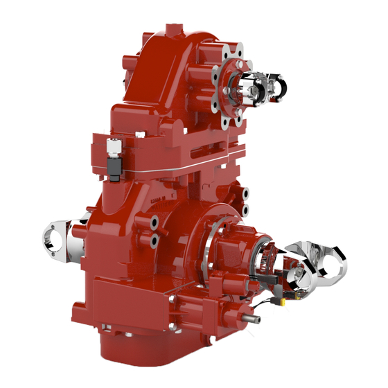
Waterous TC20 Series Installation, Operation And Maintenance Manual (107 pages)
Brand:
Waterous
| Category:
Water Pump
| Size: 17.26 MB
Table of Contents
Table of Contents
2
Safety
4
Safety Precautions
4
Introduction
7
Using this Document
7
Viewing the Document Electronically
7
Printing the Document
7
Symbols
7
Product Overview
7
System Components
8
Configurations
12
100-D, 120-D and 150-D CAFS-HLK Configurations
12
100-P and 120-P CAFS-CPK-2 Configuration
12
100-P and 120-P CAFS-CLVK Configuration
12
150-D CAFS-CSC20 Configuration
13
150-ESD CAFS-CXSC20 Configuration
13
150-ESD CAFS-TC20 Configuration
13
150-P CAFS-CLVK Configuration
14
150-P CAFS-CXVK Configuration
14
150-P CAFS-CXVPA Configuration
14
150-T CAFS-CXVT Configuration
15
200-D CAFS-HL400K Configuration
15
200-P CAFS-CXVK Configuration
15
Operation Overview
16
Compressor Components-150-P
18
Air Filtration Components
20
Oil Sump-Vertical
22
Oil Sump-Tee
24
Separator Filter
26
Oil Cooler
28
Sump Vent-Optional
30
Balance Valve
32
Auto-Sync Mode Switch
34
Auto-Sync Solenoid Assembly
36
Installation
38
Installation Overview
38
Preparing for the Installation
38
Modifying the Equipment
38
Additional Documentation
38
Determining Panel and Plate Locations
39
Determining Hose Routing
39
Determining Cable and Wire Routing
39
Dimensions-Sump, 8-Inch Long Version
40
Dimensions-Sump, 10-Inch Version
41
Dimensions-Tee Sump
42
Dimensions-Oil Cooler, 150-P
43
Dimensions-Separator Filter, 100-P and 120-P
44
Dimensions-Separator Filter, 150-P and 200-P
45
Dimensions-Air Intake Components; 100-P, 150-P, and 200-P
46
Dimensions-Balance Valve
47
Dimensions-Auto-Sync Solenoid Assembly
48
Dimensions-Optional Sump Vent Assembly
49
Dimensions-Auto-Sync Switch
50
Dimensions-Warning, Instruction, and Serial Plates
51
Dimensions-Temperature Gauge
52
Pneumatic Connections-Overview
54
Hose Connections Overview-150-P
56
Fittings Overview-150-P
58
Temperature Gauge and Sender Connections Overview
60
Installing the Oil Sump
62
Installing the Oil Cooler
63
Installing the Separator Filter
64
Installing the Balance Valve
65
Installing the Auto-Sync Solenoid Assembly
66
Mounting the Auto-Sync Switch
67
Connecting the Auto-Sync System
68
Installing the Warning, Instruction, or Serial Plate
69
Installing the Compressed Air Hoses-150-P
70
Installing the Scavenge Oil Hose-150-P
71
Installing the Oil Cooler Hoses-Oil Hoses, 150-P
72
Installing the Oil Cooler Hoses-Water Lines, 150-P
73
Installing the Balance Valve Hoses
74
Installing the PMC Hoses-150-P
75
Installing the Sump Vent Assembly
76
Installing the Pressure Gauge
77
Installing the Temperature Gauge
78
Preparing for Operation
79
Calibrating the System-Unload Mode
81
Calibrating the System-Fixed Mode
82
Calibrating the System-Auto Mode
84
Operating the System
86
Understanding the Shuttle Valve Operation
87
Operating in Unload Mode
88
Operating in Fixed Mode
89
Operating in Auto Mode
90
Shutting down the System
91
Maintenance
92
Maintenance Schedule
92
Checking the Sump Oil Level
93
Adding Oil to the Sump
94
Changing the Sump Oil
95
Changing the Air Filter
96
Changing the Separator Filter
97
Changing the Oil Filter
98
Cleaning the Wye Strainer
99
Performing the Weekly Compressor Maintenance
100
Troubleshooting
101
Troubleshooting Guide
101
Advertisement
Waterous TC20 Series Overhaul Instructions (75 pages)
Chain Driven Power Take-Off
Brand:
Waterous
| Category:
Water Pump
| Size: 5.06 MB
Table of Contents
Table of Contents
2
Drain Fluid from Transmission
9
Disconnect Output Shaft
10
End Yoke Output
10
Hydraulic Pump on Rear or Front Output
10
Disconnect Optional Accessories: Tachometer Cable
11
Drain Valve
11
Priming Pump
11
Remove from Transmission
11
Shift Unit
12
Oil Temperature Sensor
12
Eclipse™ es CAFS on Rear Output
13
Draining Compressor and Oil Cooler
13
Removal of Air Filter, Hoses and Cables
14
Disconnect Wiring
15
Remove PTO from Vehicle
16
Remove Eclipse™ es Unit from PTO
17
End Yokes or Companion Flanges
18
Oil Pan
18
Chain
18
Shift Unit
19
Shift Fork
19
Removal of Coupling (Output) Shaft
21
Removal of Drive (Input) Shaft
22
Shift Collar Retaining Ring (Input Shaft Only Configurations)
22
Pressing out Drive Shaft
23
Removing Drive Shaft, Sprocket and Housing
24
Drive (Input) Shaft
25
Shaft
25
Housing
25
Sprocket
25
Shift Fork Shoes
25
Coupling (Output) Shaft
26
Input Shaft Only Configurations
26
Input and Output Shaft Configurations
26
Removal of Output Shaft
27
Remove Cap from Case
28
TC20F Models
28
End Yoke on Front of PTO
29
End Yoke on Rear of PTO
30
Hydraulic Pump on Front of PTO
31
Hydraulic Pump on Rear of PTO
32
Eclipse™ es CAFS on Rear of PTO
33
End Yoke on Front and Hydraulic Pump on Rear
34
Hydraulic Pump on Front and End Yoke on Rear
35
Assembly of Cap
35
Inspection and Repair
36
Bearings, Oil Seals and O-Rings
36
End Yoke on Front of PTO
37
End Yoke on Rear of PTO
38
Hydraulic Pump on Front of PTO
39
Hydraulic Pump on Rear of PTO
40
Eclipse™ CAFS Rear of PTO
41
End Yoke on Front and Hydraulic Pump on Rear
42
Hydraulic Pump on Front and End Yoke on Rear
43
Attach Cap to Case: Apply Sealant to Flanges (All PTO Models)
44
TC20F Models
45
Drive Sprocket
46
Drive Shaft
46
Drive Shaft Housing
46
Shift Fork Shoes
46
Coupling Shaft
47
Input Shaft Only Configurations
47
Input and Output Shaft Configurations
47
Drive (Input) Shaft
48
Install Drive Shaft Housing on Case
48
Install Tachometer Ring in Tool
48
Install Case on Installation Tool
49
Install Drive Sprocket
50
Install Drive Shaft in Case
51
Shift Collar
52
Input and Output Shaft Configurations
52
Input Shaft Only Configurations
52
Chain
53
Coupling (Output) Shaft
54
Input and Output Shaft Configurations Wave Spring Design Prior to March 12, 2013
54
Shim Design after March 12, 2013
55
Input Shaft Only Configurations
56
Oil Seals
57
Tachometer Sensor
57
Shift Fork
58
Shift Unit
59
Oil Pan
60
End Yokes or Companion Flanges
60
Input and Output Shaft Configurations
61
Input Shaft Only Configurations
62
Eclipse™ es Unit on PTO
63
Adjusting Belt Tension
64
Installation of PTO in Vehicle
65
Connection of Propeller Shaft (Driveline)
66
Connection of Optional Accessories
67
Hydraulic Pump on Rear or Front Output
67
End Yoke on Front or Rear Output
67
Tachometer Cable
68
Drain Valve
68
Priming Pump: Mounting on Transmission
68
Hose Connections
68
Wiring Connections
69
Shift Unit
70
Oil Temperature Sensor
70
Eclipse™ es CAFS on Rear Output: Hoses and Air Filter
71
Electrical Wiring
72
Schematic
73
Lubrication: TC20 PTO
74
Eclipse es CAFS Unit
74
Shift Indication Light Operation
75
Eclipse™ es CAFS Unit
75
Advertisement
Related Products
Waterous TC10
Waterous CAFS-CL Series
Waterous CAFS-CLVK 100-P
Waterous CAFS-CLVK 120-P
Waterous CAFS-CLVK 150-P
Waterous CAFS-CP-2 Series
Waterous CAFS-CPK-2 100-P
Waterous CAFS-CSC20 150-D
Waterous CAFS-CX Series
Waterous CAFS-CXSC20 150-ESD
Waterous Categories
Water Pump
Firefighting Equipment
Industrial Equipment
Compressor
Air Compressor
More Waterous Manuals
Login
Sign In
OR
Sign in with Facebook
Sign in with Google
Upload manual
Upload from disk
Upload from URL