Table of Contents
Advertisement
Advertisement
Table of Contents

Related Manuals for TECNA TE550


Summary of Contents for TECNA TE550
- Page 1 WELDING CONTROL UNIT INSTRUCTION MANUAL TE550 FROM SOFTWARE RELEASE N. 3.31 S.p.A. via Meucci, 27 - 40024 Castel S. Pietro Terme – Bologna ITALY Tel. +390516954411 – Fax +390516954490 – http://www.tecna.net DISTRIBUTOR: DOCUMENT MAN 4142 NUMBER: EDITION: JANUARY 2012...
- Page 2 Instruction manual ITEM TE550 S.p.A. This page intentionally left blank 2/92...
-
Page 3: Table Of Contents
ITEM TE550 Instruction manual S.p.A. TABLE OF CONTENTS CHAPTER 1 - TE550 WELDING CONTROL UNIT DESCRIPTION ........6 1.1 - MAIN TECHNICAL FEATURES................6 1.2 - COMMANDS ON THE PANEL................7 1.3 - PANEL LEDs ......................8 1.4 - DESCRIPTION OF THE DISPLAYED INFORMATION .......... 9 1.5 - CONTROL UNIT SWITCH-ON ................ - Page 4 CHAPTER 14 - DESCRIPTION OF THE SIGNALS ON THE TERMINAL BOARD....84 14.1 - DESCRIPTION OF THE SIGNALS ON THE OPTIONAL BOARDS 50200 OR 50189..........................86 CHAPTER 15 - LIST OF TE550 MESSAGES ............... 87 15.1 - SYSTEM ERRORS....................87 15.2 - WORK ERRORS ....................88 15.3 - PROGRAMMING ERRORS ................
- Page 5 ITEM TE550 Instruction manual S.p.A. This page intentionally left blank The information contained in this document is subject to modification without notice. No part of this document can be either reproduced or transferred in whatever format neither by electronic nor by mechanic means for whatever purpose, without ’s written permission.
-
Page 6: Chapter 1 - Te550 Welding Control Unit Description
The TE550 is a particularly versatile welding control unit as it can be adjusted to different types of welders; it may be installed not only on spot and projection welders but on seam welders too. -
Page 7: Commands On The Panel
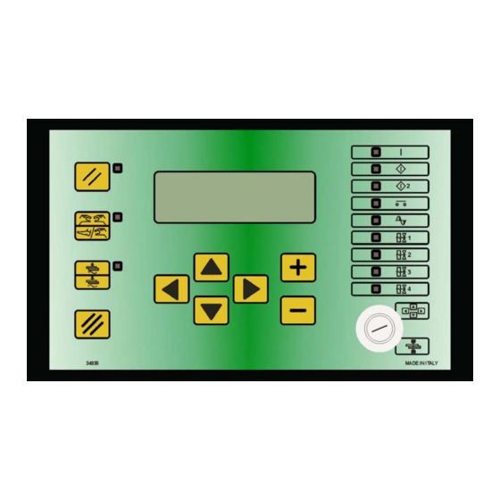
ITEM TE550 Instruction manual S.p.A. 1.2 - COMMANDS ON THE PANEL Left-hand direction key used for exiting from the programming menus. Right-hand direction key used for entering the programming menus. Upward direction key used for moving the cursor inside the upper parameter. -
Page 8: Panel Leds
Instruction manual ITEM TE550 S.p.A. 1.3 - PANEL LEDs The turning on of this LED indicates that the welder control unit is powered. If this LED is switched on it indicates that start cycle 1 command is activated. If this LED is switched on it indicates that start cycle 2 command is activated. -
Page 9: Description Of The Displayed Information
ITEM TE550 Instruction manual S.p.A. 1.4 - DESCRIPTION OF THE DISPLAYED INFORMATION Some pieces of information are displayed on the main frame following each weld sequence; this is done both for the cycles carried out in WELD mode and for the ones in NO-WELD mode. - Page 10 ENERGY 01351 joule It indicates the total energy value used for the last weld sequence. Before switching on the TE550 control unit with the supplementary expansion board item 50220, check that the inlet ELECTRODES END LIFE CLEAR (Pin 52) is not activated.
- Page 11 ITEM TE550 Instruction manual S.p.A. By means of the keys , it is possible to check the other cycles of the analysed welding. PRG 001 SPOT 12340 PRG 001 SPOT 12340 WELD TIME 02 ~ WELD TIME 10 ~ POS+ 43.26 kA 142°...
- Page 12 Indicates the number of the spot in which the measurement was performed. It is displayed in WELD and NO WELD mode. THICKNESS 02.486 mm Indicates the initial thickness of the material to be welded that the TE550 control unit measures before current flows. This value is updated in WELD and NO WELD. IDENTATION 0.000 mm Indicates the measurement of the electrode indentation into the welded material at the end of the weld cycle.
- Page 13 ITEM TE550 Instruction manual S.p.A. PRESSURE 02.3 bar Indicates the value of the pressure measurement realized by the external sensor just after the squeeze phase. This value is updated in WELD and NO WELD. PRESS. MIN 01.5 bar Indicates the value of the minimum pressure limit set when programming. This value is updated in WELD and NO WELD.
-
Page 14: Control Unit Switch-On
SUPPLY FREQUENCY 50 Hz TECNA TE550 3.31 WELD CONTROL UNIT After a few seconds, the TE550 displays the following frame and is set to a waiting condition until the RESTART key is pressed PRESS RESTART KEY [//] The RESTART command may be activated by pressing the proper key placed on the control unit (also a non-manual activation is available). -
Page 15: Chapter 2 - Control Unit Programming
ITEM TE550 Instruction manual S.p.A. CHAPTER 2 - CONTROL UNIT PROGRAMMING By placing the key in PROGRAM DATA position the following frame is displayed: -TE550 VER. 3.31-- >PROGRAM DATA SETUP MENU STEPPER MENU The first row reports the control unit type and the software version. Then the display lists all the menus allowing accessing the various control unit functions. -
Page 16: Program Data
Instruction manual ITEM TE550 S.p.A. 2.1 - PROGRAM DATA -TE550 VER. 3.31-- >PROGRAM DATA SETUP MENU STEPPER MENU The PROGRAM DATA menu contains all the parameters associated with the welding cycle, the times and the currents by means of which to carry out the welding process. -
Page 17: Percentage Adjustment Operating Mode
The correlation map between the set percentage and the controlled diodes (SCR) closing time is set in TECNA and might not be perfectly linear; in order to improve the scale linearity, it has been inserted a parameter in the FEATURES MENU allowing to delay the welding process start time. - Page 18 Instruction manual ITEM TE550 S.p.A. CONTROL MODE * CURR CURR. MIN 0.5 - 90.0 kA CURR. MAX 0.5 - 90.0 kA CONTROL MODE * ANGLE MIN 005°-180° ANGLE MAX 005°-180° CONTROL MODE * CURR. MIN 0.5 - 90.0 kA CURR. MAX 0.5 - 90.0 kA...
- Page 19 For instance, if the use is meant with 2 sheets the limit conditions would be those with either 1 or 3 sheets. The welding current is adjusted by the TE550 control unit. However, it is necessary to check the welding current value with one sheet so to be set as minimum limit and to check it with 3 sheets so to be set as maximum limit.
-
Page 20: Constant Current Operating Mode
1 or 3 sheets. The welding constant current is adjusted by the TE550 control unit (if the conduction degrees are not close to the value of 180°). However, still the conduction degrees value has to be checked with one sheet so to be set as minimum limit and to be checked with 3 sheets so to be set as maximum limit. - Page 21 ITEM TE550 Instruction manual S.p.A. TABLE CONSTANT CURRENT OPERATING MODE PARAMETERS PROGRAM DATA >PROGRAM N. WORKING MODE CONTROL MODE PARAMETER VALUE RANGE PROGRAM N. 001 - 250 WORKING MODE CONTROL MODE * QUALITY – T * SQUEEZE 1 00.5 - 99.5 cycles SQUEEZE 00.5 - 99.5 cycles...
- Page 22 Instruction manual ITEM TE550 S.p.A. QUALITY - T* IDENT IDENT. MIN 0.000 – 6.000 mm IDENT. MAX 0.000 – 6.000 mm QUALITY - T* TH+ID THICK. MIN 00.00 – 60.00 mm THICK. MAX 00.00 – 60.00 mm IDENT. MIN 0.000 – 6.000 mm IDENT.
-
Page 23: Constant Energy Operating Mode
ITEM TE550 Instruction manual S.p.A. 2.4 - CONSTANT ENERGY OPERATING MODE WORKING MODE parameter selected in ENE, the working frame is the following one: PROG. 001 SPOT 12340 WELD CYCLE 01.0 ~ RMS 43.26kA DEG 000° ENERGY 01351 joule With a constant energy control unit, all the settings are made as for conventional control units except for the ENERGY parameter and the welding time parameter, where a set rating is not required but minimum and maximum ratings are set. - Page 24 Instruction manual ITEM TE550 S.p.A. TABLE CONSTANT ENERGY OPERATING MODE PARAMETERS PROGRAM DATA >PROGRAM N. WORKING MODE CONTROL MODE PARAMETER VALUE RANGE PROGRAM N. 001 - 250 WORKING MODE CONTROL MODE * QUALITY – T * SQUEEZE 1 00.5 - 99.5 cycles SQUEEZE 00.5 - 99.5 cycles...
- Page 25 For instance, if the use is meant with 2 sheets the limit conditions would be those with either 1 or 3 sheets. The constant energy is adjusted by the TE550 control unit. However, it is necessary to check the welding current value with one sheet so to be set as minimum limit and to check it with 3 sheets so to be set as maximum limit.
-
Page 26: Working Program Parameters Description
ZERO In this mode, the control unit calculates the ZERO reference coordinate for the thickness and indentation measurements. The TE550 commutates automatically to NO WELD and one weld cycle must be carried out without material between electrodes. The ZERO procedure is required each time the machine is turned on, when the welder's secondary geometry changes and when electrodes maintenance is performed. - Page 27 ITEM TE550 Instruction manual S.p.A. THICK On the elapsing of the SQUEEZE1 and SQUEEZE times (if present), the thickness of the material to be welded is measured before the weld current flow. Check the THICKNESS measured by the control unit in the quality analysis screen.
- Page 28 Instruction manual ITEM TE550 S.p.A. By setting parameter QUALITY - T to IDENT or to TH+ID, the user activates the electrode indentation limits. In this case, two new parameters are displayed: IDENT. MIN lower limit of the electrode indentation at the end of the weld IDENT.
- Page 29 ITEM TE550 Instruction manual S.p.A. PRESSURE This parameter, expressed in bar, expresses the welding pressure value. It is used only if in the pneumatic circuit a proportional valve is present. The set value must be such that it guarantees a proper clamping force during the welding cycle. An inadequate adjustment of such value produces sparks between electrodes and sheet when the welding begins.
- Page 30 Instruction manual ITEM TE550 S.p.A. SLOPE UP The SLOPE UP parameter describes the time for attaining the programmed welding current value. The starting value of this slope always corresponds to the minimum current, whereas the final value corresponds to the current value set at parameter POWER. The SLOPE UP inclination is automatically calculated by the microprocessor according to the set values.
- Page 31 ITEM TE550 Instruction manual S.p.A. IMPULSE N. The IMPULSE N. parameter indicates the number of impulses used for carrying out the welding process. The duration of each impulse corresponds to the time set in weld parameter (WELD). The maximum pulse number which can be carried out during a welding cycle varies according to the BUTT WELD MODE parameter adjustment (present in the FEATURES menu).
- Page 32 Instruction manual ITEM TE550 S.p.A. HOLD TIME The HOLD TIME parameter indicates the time that elapses from the end of the welding process to the opening of the electrodes. It allows a quicker cooling of the welding spot and prevents the spot from being stimulated before being properly cooled.
- Page 33 ITEM TE550 Instruction manual S.p.A. THICK. MIN This parameter fixes a lower limit for the minimum thickness of the material located in between the electrodes. Before starting the weld, the measurement of the thickness of the material present between the electrodes should be greater than the minimum limit. Otherwise, an error message is displayed.
-
Page 34: Setup Menu
Instruction manual ITEM TE550 S.p.A. 2.6 - SETUP MENU -TE550 VER. 3.31-- PROGRAM DATA >SETUP MENU STEPPER MENU In this menu, the operator may find those parameters enabling to simplify the programming and better adjust the control unit to the user’s exigencies. - Page 35 ITEM TE550 Instruction manual S.p.A. AMMETER CAP. This parameter indicates the ammeter capacity of the control unit. Keep in mind that the capacity refers to simple harmonic currents and as such overflow conditions might occur even with effective current values lower than the nominal value of the carrying capacity (please, also consult the COIL RATIO parameter relevant to the sensitiveness of the connected transducer, in the SET UP MENU).
-
Page 36: Stepper Menu
Instruction manual ITEM TE550 S.p.A. 2.7 - STEPPER MENU -TE550 VER. 3.31-- PROGRAM DATA SETUP MENU >STEPPER MENU This menu contains parameters associated with the current stepper operations. STEPPER MENU >TOTAL STEPS SPOTS 1 04000 INCREMENT 1 In order to use this function, it is necessary that the electrodes dressing function (option with board 50200) is disabled. - Page 37 ITEM TE550 Instruction manual S.p.A. SPOTS 2 This parameter indicates the number of spots of which the associated segment is composed. INCREMENT 2 This parameter indicates the current stepper percentage to be attained upon the completing of the spots set in the associated segment.
-
Page 38: Current Stepper Function
Instruction manual ITEM TE550 S.p.A. 2.8 - CURRENT STEPPER FUNCTION The stepper function enables to compensate the wear of the electrodes that affects the quality of the welding spots. When the electrode diameter is enlarged, the contact section area between the electrode and the work piece to be welded increases and, as a consequence, the welding current density (Ampere/mm2) decreases. - Page 39 15 kA. It does not matter whether the TE550 is programmed for a percent adjustment or a constant current adjustment since the stepper function is operational in both modes.
- Page 40 Instruction manual ITEM TE550 S.p.A. COMPLETE USE OF THE STEPPER MENU FUNCTION (NON-LINEAR INCREMENT CURVE) It is possible to use the non-linear increment curve function by knowing the real electrodes consumption only. In the aforesaid work method, a linear welding current increment is used during the whole life span of the electrodes.
- Page 41 ITEM TE550 Instruction manual S.p.A. Example: After a number of welding tests, the ensuing life of the electrodes resulted to be 4000 welding spots and the following current values are required during the different moments of the electrodes' life. SPOTS PERFORMED...
- Page 42 At this point the operator replaces the electrodes (or resets their original diameter) and clears the spots counter, by means of the proper key, to clear stepper calculations. The TE550 resets the initial work parameters and begins a new increment phase. 42/92...
-
Page 43: Features Menu
ITEM TE550 Instruction manual S.p.A. 2.9 - FEATURES MENU -TE550 VER. 3.31-- SETUP MENU STEPPER MENU >FEATURES MENU The features menu contains the parameters that describe the complexity and typology of the welder on which the control unit works. Due to their importance, access to this menu is protected by a code. - Page 44 Instruction manual ITEM TE550 S.p.A. FIRST INSERT The FIRST INSERT parameter shows the first insertion delay. This function permits to optimize the balance of the primary consumption of the welder. After having selected this parameter, the value can be adjusted from 1 to 99.
- Page 45 ITEM TE550 Instruction manual S.p.A. PRESSURE RATIO This parameter can be used to select the optimum bar/Volt ratio for the type of proportional solenoid valve that is to be employed. It works only if the PROP. VALVE parameter is enabled. Further pieces of information are described in the paragraph INTERFACE FOR PROPORTIONAL VALVE.
- Page 46 When the parameter is set on KEY, a second function for locking the head is enabled. In this very case, in order to unlock the TE550 it is necessary first to turn the key in the PROG position and then to press the CLEAR key or to use the ERROR RESET input (when the extra board is present).
- Page 47 ITEM TE550 Instruction manual S.p.A. BACKUP USB By pressing the key <+> level with this parameter, it is activated the procedure for saving the data relevant to the parameters of all the control unit’s menus on an external USB memory.
-
Page 48: Program Copy
Instruction manual ITEM TE550 S.p.A. 2.10 - PROGRAM COPY -TE550 VER. 3.31-- STEPPER MENU FEATURES MENU >PROGRAM COPY This menu is used for copying the values of the parameters of a program to other programs without having to set one parameter at a time (so to make the programming quicker). -
Page 49: Check Input
ITEM TE550 Instruction manual S.p.A. 2.11 - CHECK INPUT -TE550 VER. 3.31-- FEATURES MENU PROGRAM COPY >CHECK INPUT This menu displays the input status on the welding control unit. It is uses for check both the efficiency and the proper working of the external devices connected to the control unit and necessary for using the welder. -
Page 50: Prog. Sequence
Instruction manual ITEM TE550 S.p.A. 2.12 - PROG. SEQUENCE -TE550 VER. 3.31-- PROGRAM COPY CHECK INPUT >PROG. SEQUENCE The parameters necessary for activating the program sequence operating mode are entered in this menu. When using this operating mode, the welding control unit orders the welder to carry a welding spots sequence out by automatically deciding both the working program at each spot and the spots welding order without needing a program external selection. - Page 51 ITEM TE550 Instruction manual S.p.A. STEP 3 WELDS This parameter’s value indicates the welding spots number to be carried out with the program coupled with the same step. STEP 4 PRG. This parameter indicates the program number that the welder has to carry out and is coupled with the STEP 4 WELDS parameter.
- Page 52 Instruction manual ITEM TE550 S.p.A. In this specific case, as shown by the below scheme, the following welding spots are carried out in sequence: 4 welding spots with program 03 2 welding spots with program 07 6 welding spots with program 11 ...
-
Page 53: Tip-Dressing
This function is displayed only if the expansion (optional) board item 50200 is installed on the control unit. Before switching the TE550 control unit on with the 50200 supplementary expansion board, check that the ELECTRODES END LIFE CLEAR inlet (Pin 52) is disabled. - Page 54 Instruction manual ITEM TE550 S.p.A. DRESSING NUMBER This parameter indicates the number of tip-dressing to be carried out on the electrodes before these ones become useless. If this parameter is set to zero, the tip-dressing is not carried out. SPOT DRESSING It indicates the number of welding spots per each tip-dressing.
- Page 55 ITEM TE550 Instruction manual S.p.A. EXAMPLE: The parameters outlined in the table below were set (with a set work program such as, for example, “WORKING MODE” IK) with an initial current value set to 10KA. PARAMETER VALUE DRESSING NUMBER SPOT DRESSING...
- Page 56 Instruction manual ITEM TE550 S.p.A. The chart below shows the time-study and modalities of the signals used for this operating mode (referring to the values in the foregoing table). From the moment the control unit activates the DRESSING ALARM output, it may be reset at any time by activating the DRESSING CLEAR input as shown in the foregoing chart for dressings 1, 3 and 4.
-
Page 57: Thickness Sensor
ITEM TE550 Instruction manual S.p.A. 2.14 - THICKNESS SENSOR -TE550 VER. 3.31-- CHECK INPUT PROG. SEQUENCE >THICKNESS SENSOR In order to view and access this menu, the user must commutate parameter THICKNESS SENSOR to ON inside the FEATURES MENU. The THICKNESS SENSOR menu contains the parameters for configuring the linear position sensor. - Page 58 Instruction manual ITEM TE550 S.p.A. LINEAR SENSOR This parameter activates or deactivates the linear position sensors. If a sensor initialization error occurs, the parameter commutates to OFF automatically. Sensor identification parameters are not deleted. The enabling of the position sensors makes available the measurements relative both to the initial thickness of the sheets to be welded and the indentation of the electrode at the end of the weld, and relative limits.
- Page 59 4) Go to the PROGRAM DATA menu: set parameter QUALITY - T to IDENT. in the weld program. 5) Weld a short circuited spot and observe the measurement of the IDENTATION displayed on the TE550 control unit at the end of the weld. PRG 005 SPOT 01234 THICKNESS 00.000 mm...
-
Page 60: Adjusting The First Insert Delay
Instruction manual ITEM TE550 S.p.A. 2.15 - ADJUSTING THE FIRST INSERT DELAY During installation it is compulsory to adjust the first insert delay both to reduce absorption from the power line and to reduce power dissipation at the transformer's primary (risk of damaging the weld transformer permanently). -
Page 61: Chapter 3 - Seam Weld Work Mode
ITEM TE550 Instruction manual S.p.A. CHAPTER 3 - SEAM WELD WORK MODE FEATURES MENU AUTORETAIN NC CONTACTS >SEAM WELD MODE With parameter SEAM WELD MODE set to ON, the work screen is as follows: PROG. 001 SPOT 12340 WELD CYCLE 01.0 ~ CURRENT RMS 43.26 kA... - Page 62 Instruction manual ITEM TE550 S.p.A. CONTROL MODE * CURR CURR. MIN 0.5 - 90.0 kA CURR. MAX 0.5 - 90.0 kA CONTROL MODE * ANGLE MIN 005°-180° ANGLE MAX 005°-180° CONTROL MODE * CURR. MIN 0.5 - 90.0 kA CURR. MAX 0.5 - 90.0 kA...
- Page 63 ITEM TE550 Instruction manual S.p.A. NOTES FOR THE SEAM WELDING WORKING MODE ONLY: The welding currents set in the POWER 3 and CURRENT 3 parameters can be recalled by means of the closing of RIC5 (Pin12) input. The external recalls RIC5, RIC6 and RIC7 are not activated in the function of recall from an external device program.
-
Page 64: Chapter 4 - Butt Weld Work Mode
Instruction manual ITEM TE550 S.p.A. CHAPTER 4 - BUTT WELD WORK MODE FEATURES MENU CONTACTS NC SEAM WELD MODE >BUTT WELD MODE With parameter BUTT WELD MODE set to ON, the work screen is as follows: PROG. 001 SPOT 12340 WELD CYCLE 01.0 ~... - Page 65 ITEM TE550 Instruction manual S.p.A. CONTROL MODE* CURR CURR. MIN 0.5 - 90.0 kA CURR. MAX 0.5 - 90.0 kA CONTROL MODE * ANGLE MIN 005°-180° ANGLE MAX 005°-180° CONTROL MODE * CURR. MIN 0.5 - 90.0 kA CURR. MAX 0.5 - 90.0 kA...
- Page 66 Instruction manual ITEM TE550 S.p.A. CONTROL MODE* CURR. MIN 0.5 - 90.0 kA CURR. MAX 0.5 - 90.0 kA ANGLE MIN 005°-180° ANGLE MAX 005°-180° NOTES FOR THE BUTT WELDING WORKING MODE ONLY: When the BUTT WELD MODE is set to ON, the seam welding (SEAM WELD MODE) and high speed welding (SER.
-
Page 67: Chapter 5 - Ser. Spot Mode
HIGH SPEED. The TE550 control unit carries the first cycle out with a squeeze phase value equal to the sum of the times set in the SQUEEZE1 and SQUEEZE parameters, while, in the following cycles, the value is equal to the time set in the SQUEEZE parameter. -
Page 68: Chapter 6 - Cascade Work Mode
- AUX input - END CYCLE output All the TE550 control units receive the cycle start signal simultaneously. Connect the END CYCLE signal to the AUX input of the next control unit. It is advisable to program parameter CASCADE MODE, of the last control unit, to OFF in order to use the END CYCLE signal with the normally open contact. -
Page 69: Chapter 7 - The Work Cycle
S.p.A. CHAPTER 7 - THE WORK CYCLE The work cycle carried out by the TE550 is described by adjusting the programming parameters. These parameters describe operating times and current adjustments that make up the work cycle when run in sequence. -
Page 70: Chapter 8 - Stop Bad Spots
Instruction manual ITEM TE550 S.p.A. CHAPTER 8 - STOP BAD SPOTS The machine may be stopped when a consecutive series of welds fall out of the regulated limits. The number of consecutive welds that causes the control unit to stop is regulated through parameter STOP BAD SPOTS in the SETUP MENU (for the programming directions, see the relevant paragraph). - Page 71 ITEM TE550 Instruction manual S.p.A. Conduction angle limits This mode is activated by setting parameter CONTROL MODE to DEG. In this case two new parameters are displayed: ANGLE MIN conduction angle lower limit ANGLE MAX conduction angle upper limit that permit setting current conduction angle limit values.
-
Page 72: Chapter 9 - Welds Counter Function
Instruction manual ITEM TE550 S.p.A. CHAPTER 9 - WELDS COUNTER FUNCTION A counter has been built into the control unit to count the run welds. The max limit may be programmed. During operations, the counter's current value is displayed. The counter increases at each weld. -
Page 73: Chapter 10 - Description Of The Interface Outputs
ITEM TE550 Instruction manual S.p.A. CHAPTER 10 - DESCRIPTION OF THE INTERFACE OUTPUTS 10.1 - WELD ERROR (WRONG) The WRONG signal identifies a wrong weld which is out of the limits set conforming to the table shown below. The output, which is an opto-electronic contact, closes at the beginning of the hold time and... - Page 74 Instruction manual ITEM TE550 S.p.A. WRONG SIGNAL ACTIVATION TABLE WORKING MODE -► CONTROL MODE ▼ Error due to no current Min time signal Max time VE out of scale Error due to no electrodes voltage ...
-
Page 75: End Cycle
ITEM TE550 Instruction manual S.p.A. 10.2 - END CYCLE The END CYCLE signal indicates the end of the weld cycle. The output, which is an opto- electronic contact, closes at the end of the hold time and may last according to the following possibilities: 1. -
Page 76: Chapter 11 - Selecting The Work Program Through External Recalls
Instruction manual ITEM TE550 S.p.A. CHAPTER 11 - SELECTING THE WORK PROGRAM THROUGH EXTERNAL RECALLS The table below shows which inputs are required to call the work program. The selection is made through seven inputs, suitably activated in the following combinations. -
Page 77: Chapter 12 - Double Stroke Function
ITEM TE550 Instruction manual S.p.A. CHAPTER 12 - DOUBLE STROKE FUNCTION In addition to the 3 solenoid valves that are part of the work cycle, the control unit manages a fourth solenoid valve aside from the work cycle to command the double stroke, which is also called the approach stroke. -
Page 78: Chapter 13 - Options
CHAPTER 13 - OPTIONS 13.1 - RS-232 SERIAL INTERFACE The RS-232 serial expansion card, code 50214, permits the user to connect the TE550 to a printer or a personal computer which must be fitted with a RS232 serial interface card, to document production data. - Page 79 00014 DEG MAX 00.000 0.000 00.0 10,0 06.00 00000 00015 DEG MAX 00.000 0.000 00.0 Print example of the work program parameters values: WELD CONTROL UNIT TE550 REV. 3.31 PROGRAM N. WORKING MODE CONTROL MODE SQUEEZE 1 10.0 SQUEEZE 20.0 PRESSURE 05.0...
-
Page 80: Rs-485 Serial Interface
Instruction manual ITEM TE550 S.p.A. 13.2 - RS-485 SERIAL INTERFACE The RS-485 serial expansion card, code 50209, permits connecting the control unit in the network to other welding control units and to a central personal computer for programming the control unit or for documenting production data. The card interfaces with the control unit... -
Page 81: Interface For Proportional Valve
ITEM TE550 Instruction manual S.p.A. 13.3 - INTERFACE FOR PROPORTIONAL VALVE This interface card, code 50220, permits the control unit to control a proportional valve and set the welding pressure in bars as one of the program's parameters. This interface requires external power supply. -
Page 82: Interface For Pressure Sensor
S.p.A. 13.4 - INTERFACE FOR PRESSURE SENSOR The TE550 welding control unit, besides its standard features, may measure the voltage at the electrodes tips of a welder for the constant energy functioning by means of the optional board 50200. Or, it may measure the welding pressure detected by a pressure sensor externally placed from the unit by means of the optional board 50189. - Page 83 When the squeeze time is over, if the pressure value measured by the control unit is within the limits set in the program, then the TE550 proceeds with the welding phase itself. Otherwise, as long as there is a start cycle, the control unit will display a screen showing the measured pressure value (PRESSURE) and the limits set in the program (PRESS.
-
Page 84: Chapter 14 - Description Of The Signals On The Terminal Board
This input is used for calling the weld programmes directly from the outside. This input is active closed on the COM1. If the TE550 control unit is set to SEAM WELD mode, this input calls the second weld current (POWER 3 or CURRENT 3 parameters). - Page 85 EN60204. Connect to solenoid valve 3 (FORGE). Command suitable for coil control at 24VDC. Max 5W. In case the TE550 is set to SEAM WELD mode, this output controls the seam start (MOTOR DELAY parameter). COM2 Common for outputs with 0V reference. Connected to GND conforming to regulation EN60204 Connect to solenoid valve 4 (DOUBLE STROKE).
-
Page 86: Description Of The Signals On The Optional Boards 50200 Or 50189
The fuses used are “LITTELFUSE” 47303.5 Tecna article, Code 21954. Component “BC” stands for the two-position PROG - RUN key lock installed on the control unit's front panel, traced as code “RS” 321054 or as a Tecna article, Code 21955. 86/92... -
Page 87: Chapter 15 - List Of Te550 Messages
ITEM TE550 Instruction manual S.p.A. CHAPTER 15 - LIST OF TE550 MESSAGES 15.1 - SYSTEM ERRORS MESSAGE CAUSE REMEDY An error occurred in the electronic Contact service center. ERROR RELE1 OPEN component that activates the outputs. The state of relay 1 is off, therefore ERROR RELE1 OPEN faulty. -
Page 88: Work Errors
Instruction manual ITEM TE550 S.p.A. 15.2 - WORK ERRORS MESSAGE CAUSE REMEDY The emergency signal required Carefully check electrical NO EMERGENCY ERROR to run the control unit was connections of the emergency omitted or a relay error occurred signal. OR RELAY RESTART... - Page 89 Contact service center. POSITION SENSOR The CAN card coded 50274 was Check that the CAN is properly not detected at switch-on. connected to the TE550 control NOT PROGRAMMABLE unit. The initial thickness of the sheets Reset the error and check the...
- Page 90 Instruction manual ITEM TE550 S.p.A. The initial thickness of the sheets Reset the error and check the THICKNESS in between the electrodes is material between the electrodes. greater than that set in the OVER HIGH LIMIT THICK. MAX limit. IDENTATION...
-
Page 91: Programming Errors
ITEM TE550 Instruction manual S.p.A. 15.3 - PROGRAMMING ERRORS MESSAGE CAUSE REMEDY During a work cycle in CONTROL Modify the parameter that WORKING MODE ENE MODE ENE, the minimum weld time triggered the error. is higher than the maximum weld MIN TIME >... -
Page 92: Chapter 16 - Technical Specifications
Instruction manual ITEM TE550 S.p.A. CHAPTER 16 - TECHNICAL SPECIFICATIONS POWER SUPPLY: 24Vac +/- 10% FREQUENCY: 50/60Hz +/- 1% CONSUMPTION: 0.3A WITHOUT LOAD / 2A WITH COMPLETE LOADS MAX ALTITUDE: 1000m RELATIVE HUMIDITY: from 40% to 80% WORK TEMPERATURE: 0°C to 50°C / 32°F to 122°F WEIGHT: 530g / 1.1685 lb...
Need help?
Do you have a question about the TE550 and is the answer not in the manual?
Questions and answers