Table of Contents
Advertisement
Advertisement
Table of Contents

Related Manuals for TECNA TE700


Summary of Contents for TECNA TE700
- Page 1 WELDING CONTROL UNIT INSTRUCTION MANUAL TE700 FROM SOFTWARE RELEASE N° 1.13 ® TECNA S.p.A. via Grieco 25/27 - 40024 Castel S. Pietro Terme – Bologna ITALY Tel. +390516954411 – Fax +390516954490 – http://www.tecna.net DISTRIBUTOR: DOCUMENT MAN 4147 NUMBER: EDITION: APRIL 2010...
- Page 2 Instruction Manual ITEM TE700 TECNA S.p.A. This page is intentionally left blank. 2/128...
-
Page 3: Table Of Contents
ITEM TE700 Instruction Manual TECNA S.p.A. TABLE OF CONTENTS CHAPTER 1 - TE700 WELDING CONTROL UNIT DESCRIPTION Pag. 6 1.1 - MAIN TECHNICAL FEATURES Pag. 7 1.2 - PANEL CONTROLS Pag. 8 1.3 - PANEL LEDs Pag. 9 1.4 - DESCRIPTION OF DISPLAYED INFORMATION Pag. - Page 4 11.2 - INTERFACE FOR PROPORTIONAL VALVE Pag. 116 CHAPTER 12 - DESCRIPTION OF THE SIGNALS ON THE TERMINAL Pag. 117 BOARD CHAPTER 13 - LIST OF TE700 MESSAGES Pag. 120 13.1 - SYSTEM ERRORS – TE700 Pag. 120 13.2 - SYSTEM ERRORS - INVERTER Pag.
- Page 5 The information contained in this document is subject to modification without prior notice. No part of this document can be either reproduced or transferred in whatever format neither by electronic nor by mechanic means for whatever purpose, without TECNA’s written permission. TECNA is a registered brand. 5/128...
-
Page 6: Chapter 1 - Te700 Welding Control Unit Description
IGBT power unit that adjusts the welding current. The TE700 is a particularly versatile control unit since it can be adapted to different types of welders. In addition to the spot and projection welders, it may also be installed on seam welders and work with constant current, FIX, constant power, constant voltage, constant energy adjustment and in dynamic mode. -
Page 7: Main Technical Features
ITEM TE700 Instruction Manual TECNA S.p.A. 1.1 – MAIN TECHNICAL FEATURES Simplified programming via 6 keys and a backlit alphanumeric LCD. Inverter command with medium frequency IGBT, with possibility of choosing the operating frequency of the inverter between 1000 Hz and 4000 Hz. -
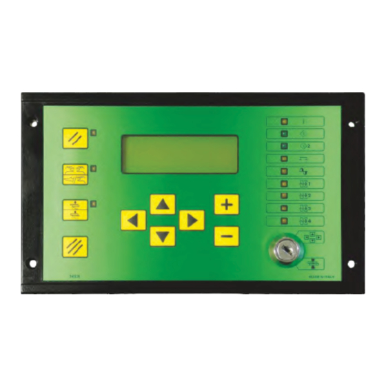
Page 8: Panel Controls
Instruction Manual ITEM TE700 TECNA S.p.A. 1.2 – PANEL CONTROLS Left-hand direction key used for exiting from the programming menus. Right-hand direction key used for entering the programming menus. Upward direction key used for moving the cursor inside the upper parameter. -
Page 9: Panel Leds
ITEM TE700 Instruction Manual TECNA S.p.A. 1.3 – PANEL LEDs The turning on of this LED indicates that the welder control unit is powered. The turning on of this LED indicates that start cycle 1 command is activated. The turning on of this LED indicates that start cycle 2 command is activated. -
Page 10: Description Of Displayed Information
Instruction Manual ITEM TE700 TECNA S.p.A. 1.4 – DESCRIPTION OF DISPLAYED INFORMATION Main work screen The main screens display some information after every run weld cycle, both for cycles carried out in weld mode, with the control unit set to WELD mode, and for cycles carried out in NO WELD mode. - Page 11 ITEM TE700 Instruction Manual TECNA S.p.A. IRMS 020.26kA It indicates the value of the current with which the last weld was carried out. In WELD mode the value may range from 000.00 kA to 200.00 kA. In NO WELD mode the value is 000.00 kA.
- Page 12 Instruction Manual ITEM TE700 TECNA S.p.A. ST 001-020 001 Indicates the current spot inside the set welding sequence. 020 Indicates the total number of weld spots that make the sequence up. The indication of the number of the spot inside the sequence increases both in WELD mode and in NO WELD mode.
- Page 13 ITEM TE700 Instruction Manual TECNA S.p.A. FE ZN 10 is the alphanumeric identifier associated with the selected weld program. These are 8 characters that are defined at will by the operator to better identify the weld program. It is displayed both in WELD and NO WELD mode.
- Page 14 Instruction Manual ITEM TE700 TECNA S.p.A. The time value is displayed both in WELD mode and in NO WELD mode. The value of the current is displayed only in WELD mode whilst 000.00KA is displayed in NO WELD mode. If PRE ----mS ---.—KA is displayed, this means that the programming of the pre-weld parameter is disabled inside the control unit.
- Page 15 ITEM TE700 Instruction Manual TECNA S.p.A. SPOT 02400 It indicates the number of the present spot. The counter increases when the control unit is in WELD mode and does not increase when the unit is in NO WELD mode. INC1 001.0 % 0F 060%...
- Page 16 Instruction Manual ITEM TE700 TECNA S.p.A. DRESSING – 00500 It indicates the remaining number of weld spots before the need to carry out the electrodes' dressing or changing operations. The counter does not decrease when the control unit is in NO WELD mode.
- Page 17 ERR: 162 This is the code of the error displayed. INVERTER It indicates if the error originated from the INVERTER or the TE700 control unit. SPOT: 00001 It indicates the value of the spot counter when the signalled error occurred.
-
Page 18: Control Unit Switch-On
MAINS FREQUENCY 50 Hz Both the type of control unit and the relevant software version are displayed. TE700 REV. 1.09 WELD CONTROL UNIT In order to complete the control unit switch-on sequence, the operator is asked to press the RESTART button or to generate the RESTART sequence through external program recalls. - Page 19 ITEM TE700 Instruction Manual TECNA S.p.A. This RESTART button enables the control unit's commands and outputs. It must be pressed every time the control unit is powered. As soon as the RESTART command is issued, all the devices connected to the VAUX output are supplied and the charging procedure for the capacitors bank is started on the inverter.
-
Page 20: Chapter 2 - Control Unit Programming
TECNA S.p.A. CHAPTER 2 – CONTROL UNIT PROGRAMMING By placing the key in PROGRAM DATA position the following screen is displayed: -TE700 VER. 1.09 -- >PROGRAM DATA SETUP MENU STEPPER MENU The first row reports the control unit type and the software version. Then the display lists all the menus allowing accessing the various control unit functions. -
Page 21: Program Data
ITEM TE700 Instruction Manual TECNA S.p.A. 2.1 – PROGRAM DATA -TE700 VER. 1.09-- >PROGRAM DATA SETUP MENU STEPPER MENU The PROGRAM DATA menu contains all the weld cycle parameters, the times and the currents which to carry out the welds with. - Page 22 Instruction Manual ITEM TE700 TECNA S.p.A. TRAFO). If 1 was set as max value, the value of the parameter cannot be changed by the operator. The WELD TOOL parameter permits identifying up to max 4 different types of electrodes used during the welding operations.
-
Page 23: Constant Current Operating Mode
ITEM TE700 Instruction Manual TECNA S.p.A. 2.2 - CONSTANT CURRENT OPERATING MODE (IK) When the weld control unit works in constant current mode, the current value which to carry out the welding with may be set directly. During the welding procedure, the control unit measures the real effective value (RMS) of the welding current every mS and maintains the set current according to a mathematical correction algorithm. - Page 24 Instruction Manual ITEM TE700 TECNA S.p.A. TABLE WITH CONSTANT CURRENT OPERATING MODE PARAMETERS PARAMETER RANGE VALUE PROGRAM N. 001 – 300 WORKING MODE CONTROL MODE * QUALITY – T* QUALITY – R * SQUEEZE 1 0.5 – 99.0 cycles SQUEEZE 00.0 –...
- Page 25 ITEM TE700 Instruction Manual TECNA S.p.A. QUALITY –T * THICK THICK. MIN 00.00 – 60.00 mm THICK MAX 00.00 – 60.00 mm QUALITY –T * IDENT IDENT. MIN 0.000 – 6.000 mm IDENT. MAX 0.000 – 6.000 mm QUALITY –T * TH+ID THICK.
- Page 26 1 or 3 sheets. The constant welding current is adjusted by the TE700 control unit (if the value of the r parameter for using the welding unit is less than 100.0%). The operator must then check the values of the r indicator when welding with 1 sheet and set this value as minimum limit and if welding with 3 sheets, set this value as maximum limit.
-
Page 27: Fix Operating Mode
ITEM TE700 Instruction Manual TECNA S.p.A. 2.3 – FIX OPERATING MODE (FIX) In FIX working mode the inverter welding unit does not make any adjustments to the current supplied during welding. The operator must set the power slicing percentage supplied by the inverter, which ranges from 5% to 100%. - Page 28 Instruction Manual ITEM TE700 TECNA S.p.A. TABLE WITH FIX OPERATING MODE PARAMETERS PARAMETER RANGE VALUE PROGRAM N. 001 – 300 WORKING MODE CONTROL MODE * QUALITY – T* QUALITY – R * SQUEEZE 1 0.5 – 99.0 cycles SQUEEZE 00.0 – 99.0 cycles PRESSURE 00.5 –...
- Page 29 ITEM TE700 Instruction Manual TECNA S.p.A. QUALITY –T * THICK THICK. MIN 00.00 – 60.00 mm THICK MAX 00.00 – 60.00 mm QUALITY –T * IDENT IDENT. MIN 0.000 – 6.000 mm IDENT. MAX 0.000 – 6.000 mm QUALITY –T * TH+ID THICK.
- Page 30 Instruction Manual ITEM TE700 TECNA S.p.A. the material to be welded. This condition applies as long as the welding current is less than the maximum current of the welding transformer. If the welding current tends to exceed the value set as welding transformer max current, the welder intervenes automatically by reducing the set current slicing value in real time to maintain current within the set limits.
-
Page 31: Constant Secondary Voltage Operating Mode
ITEM TE700 Instruction Manual TECNA S.p.A. 2.4 - CONSTANT SECONDARY VOLTAGE OPERATING MODE (VEK) When working with constant secondary voltage, the welder calculates the real effective value (RMS) of the voltage at the electrodes every mS and keeps the set voltage value constant according to a mathematical algorithm. - Page 32 Instruction Manual ITEM TE700 TECNA S.p.A. TABLE WITH CONSTANT SECONDARY VOLTAGE OPERATING MODE PARAMETERS PARAMETER RANGE VALUE PROGRAM N. 001 – 300 WORKING MODE CONTROL MODE * QUALITY – T* QUALITY – R * SQUEEZE 1 0.5 – 99.0 cycles SQUEEZE 00.0 –...
- Page 33 ITEM TE700 Instruction Manual TECNA S.p.A. QUALITY –T * THICK THICK. MIN 00.00 – 60.00 mm THICK MAX 00.00 – 60.00 mm QUALITY –T * IDENT IDENT. MIN 0.000 – 6.000 mm IDENT. MAX 0.000 – 6.000 mm QUALITY –T * TH+ID THICK.
-
Page 34: Constant Power Operating Mode
Instruction Manual ITEM TE700 TECNA S.p.A. 2.5 – CONSTANT POWER OPERATING MODE (PWK) When working in constant power mode, the inverter calculates the real effective value (RMS) of the secondary voltage and the secondary current every mS and maintains the product constant through a mathematical algorithm during mains voltage changes. - Page 35 ITEM TE700 Instruction Manual TECNA S.p.A. TABLE WITH CONSTANT POWER OPERATING MODE PARAMETERS PARAMETER RANGE VALUE PROGRAM N. 001 – 300 WORKING MODE CONTROL MODE * QUALITY – T* QUALITY – R * SQUEEZE 1 0.5 – 99.0 cycles SQUEEZE 00.0 –...
- Page 36 Instruction Manual ITEM TE700 TECNA S.p.A. THICK MAX 00.00 – 60.00 mm QUALITY –T * IDENT IDENT. MIN 0.000 – 6.000 mm IDENT. MAX 0.000 – 6.000 mm QUALITY –T * TH+ID THICK. MIN 00.00 – 60.00 mm THICK MAX 00.00 –...
-
Page 37: Constant Energy Operating Mode
ITEM TE700 Instruction Manual TECNA S.p.A. 2.6 – CONSTANT ENERGY OPERATING MODE (ENE) With a constant energy control unit, all the settings are made as for conventional control units except for the ENERGY parameter and the welding time parameter, where a set rating is not required but minimum and maximum ratings are set. - Page 38 Instruction Manual ITEM TE700 TECNA S.p.A. PARAMETER RANGE VALUE PROGRAM N. 001 – 300 WORKING MODE CONTROL MODE * QUALITY – T* QUALITY – R * SQUEEZE 1 0.5 – 99.0 cycles SQUEEZE 00.0 – 99.0 cycles PRESSURE 00.5 – 10.0 bar FORGE DELAY 00 –...
- Page 39 ITEM TE700 Instruction Manual TECNA S.p.A. THICK. MIN 00.00 – 60.00 mm THICK MAX 00.00 – 60.00 MM QUALITY –T * IDENT IDENT. MIN 0.000 – 6.000 mm IDENT. MAX 0.000 – 6.000 mm QUALITY –T * TH+ID THICK. MIN 00.00 –...
- Page 40 1 or 3 sheets. The constant energy is adjusted by the TE700 control unit. The operator must then check the current slicing percentage of the inverter with 1 sheet and set this value as minimum limit. The value with 3 sheets should be set as maximum limit.
- Page 41 ITEM TE700 Instruction Manual TECNA S.p.A. 2.7 - OPERATING IN DYNAMIC MODE (DYN) The DYNAMIC MODE is an adaptive type inverter working mode. This unit is capable of detecting faulty conditions, during the welding operation, such as the imperfect contact of the sheets to be welded, presence of impurities between the pieces to be welded, presence of shunts near the electrodes or wear of the electrodes.
- Page 42 Instruction Manual ITEM TE700 TECNA S.p.A. TABLE WITH DYNAMIC OPERATING MODE PARAMETERS PARAMETER RANGE VALUE PROGRAM N. 001 – 300 WORKING MODE CONTROL MODE * QUALITY – T* QUALITY – R * SQUEEZE 1 0.5 – 99.0 cycles SQUEEZE 00.0 – 99.0 cycles PRESSURE 00.5 –...
- Page 43 ITEM TE700 Instruction Manual TECNA S.p.A. QUALITY –T * THICK THICK. MIN 00.00 – 60.00 mm THICK MAX 00.00 – 60.00 mm QUALITY –T * IDENT IDENT. MIN 0.000 – 6.000 mm IDENT. MAX 0.000 – 6.000 mm QUALITY –T * TH+ID THICK.
- Page 44 2, pre welding and post welding. The possibility of selecting a specific work mode depends on the configuration of the TE700 + INVERTER units and on the configuration of the spot welder on which they are installed.
- Page 45 ITEM TE700 Instruction Manual TECNA S.p.A. IDENT At the end of the passage of the welding current and before the execution of the HOLD TIME, the electrodes penetration into the material (that took place during the welding operation), is measured. In order to identify the correct penetration values according to the type of material to be welded, consult the specific welding tables.
- Page 46 An insufficient adjustment of this value produces sparks between the electrodes and the sheet during the welding operation. This parameter is activated after the activation of the FORGE and PROP. VALVE parameters in the TE700 FEATURES menu.
- Page 47 ITEM TE700 Instruction Manual TECNA S.p.A. PRE-RO The value expressed in this parameter indicates the current slicing percentage which the PRE-WELD is carried out with. This parameter is activated through the specific function in the SETUP MENU. This parameter is displayed only in FIX WORKING MODE.
- Page 48 Instruction Manual ITEM TE700 TECNA S.p.A. CURR. MAX The parameter indicates the maximum current that can circulate on the secondary circuit when the unit's adjustment mode is not by constant current. The task of this parameter is to protect the integrity of the tool used against excessive increases in the welding current.
- Page 49 ITEM TE700 Instruction Manual TECNA S.p.A. CURRENT 2 The value expressed in this parameter indicates the current which the WELD is carried out with. This parameter is displayed only in the IK or ENE WORKING MODE. This parameter is activated through the specific function in the SETUP MENU.
- Page 50 Activate this parameter by setting the CONTROL MODE to CUR., otherwise the parameter is not displayed during the programming phase. The display of this parameter depends on the configuration of the machine set in the FEATURES INVERTER and FEATURES TE700 menus.
- Page 51 Activate this parameter by setting the CONTROL MODE to RO, otherwise the parameter is not displayed during the programming phase. The display of this parameter depends on the configuration of the machine set in the FEATURES INVERTER and FEATURES TE700 menus.
- Page 52 Activate this parameter by setting the CONTROL MODE to ENE, otherwise the parameter is not displayed during the programming phase. The display of this parameter depends on the configuration of the machine set in the FEATURES INVERTER and FEATURES TE700 menus.
- Page 53 Activate this parameter by setting QUALITY-T. to IDENT or TH+ID, otherwise the parameter is not displayed during the programming phase. The display of this parameter depends on the configuration of the machine set in the FEATURES INVERTER and FEATURES TE700 menus.
-
Page 54: Setup Menu
2 command. PRINTER SPOTS With this parameter, if the serial port is setup for print (see FEATURES TE700), the operator can choose which welding spots to be printed. It is possible to disable the print, print all spots or only the spots whose current value remains out of the set limits values. - Page 55 ITEM TE700 Instruction Manual TECNA S.p.A. STOP BAD SPOT T1 The STOP BAD SPOT T1 parameter allows the operator to program the control unit so that it stops when welds are carried out with weld programs associated with tool number 1 with values of the controlled parameter beyond the set limits.
- Page 56 Instruction Manual ITEM TE700 TECNA S.p.A. PRE-WELD When set to ON it activates the pre-weld parameters in all the programs. POST-WELD When set to ON it activates the parameters relevant to the post welding, the cold 3 time and the slope down in all the programs.
-
Page 57: Stepper Menu
ITEM TE700 Instruction Manual TECNA S.p.A. 2.10 - STEPPER MENU -TE700 VER. 1.09-- >PROGRAM DATA SETUP MENU STEPPER MENU This menu contains parameters associated with the current stepper operations. STEPPER MENU >TOOLS N° STEPPER WELD STEPPER TIME The unit can manage up to max 4 different stepper modules, one for each welding tool managed by the control unit. - Page 58 Instruction Manual ITEM TE700 TECNA S.p.A. STEPPER MENU PARAMETERS TABLE PARAMETER PARAMETER DESCRIPTION RANGE VALUE TOOLS N° Number of the tool which the 1 – 4 parameterization refers to STEPPER WELD Stepper of the main adjustment OFF – ON L1 – ON L2...
- Page 59 ITEM TE700 Instruction Manual TECNA S.p.A. the movement times are not increased. The time increase may be left deactivated or arbitrarily associated with one of the two available stepper laws. STEPPER THICK. This parameter may be modified only if the sensors that check for the position of the electrodes have been correctly installed in the spot welder.
- Page 60 Instruction Manual ITEM TE700 TECNA S.p.A. INCREMENT 3-L2 This increment indicates the percentage increase relevant to the third segment of stepper law SPOTS 4 This parameter indicates the number of spots which the associated segment is composed of. INCREMENT 4-L1 This increment indicates the percentage increase relevant to the fourth segment of stepper law 1.
-
Page 61: Adjustment Stepper Function
ITEM TE700 Instruction Manual TECNA S.p.A. 2.11 - ADJUSTMENT STEPPER FUNCTION The adjustment stepper function permits correcting the wear of the electrodes that affects the quality of the welds. When the diameter of the electrodes increases, so does the contact... - Page 62 Instruction Manual ITEM TE700 TECNA S.p.A. Example: The welding tests proved that: the electrode life corresponds to 2000 welding spots; that with new electrodes the required current is 15 kA; that after 2000 spots the electrodes diameter increment requires a 19 kA current.
- Page 63 The TE700 resets the initial work parameters and begins a new stepper phase. COMPLETE USE OF THE STEPPER FUNCTION (NON-LINEAR INCREMENT CURVE) It is possible to use the non-linear increment curve function by knowing the real electrodes consumption only.
- Page 64 Instruction Manual ITEM TE700 TECNA S.p.A. The N.TOTAL STEPS parameter determines the number of segments to be entered in the stepper curve. Enter the number of welds that make up the segment in parameters SPOTS 1,2… and enter the relevant percentage increase to be carried out in parameter INCREMENT 1-L1,2-L1….
- Page 65 Now the operator replaces the electrodes (or restores their original diameter) and clears the spots counter relevant to the tool the electrodes of which were replaced to clear the stepper calculations. The TE700 resets the initial work parameters and begins a new stepper phase. 65/128...
-
Page 66: Features Te700
STEPPER MENU >FEATURES TE700 The TE700 installation menu contains the parameters that describe the complexity and the typology of the welder on which the control unit works. Access to said menu is protected by an access code due the importance of these parameters. - Page 67 ITEM TE700 Instruction Manual TECNA S.p.A. THICK SENSOR Enabling of the parameters relevant to ON – OFF the thick sensor (position sensor) STEPPER TIME Enabling of the stepper functionality on ON – OFF the welding time SERIAL COM. The operator may choose whether to activate the serial data transmission port and how it is to be used, connect a printer (232) or connect the control unit to a data supervision network (485), or not to use this option (OFF).
- Page 68 When the parameter is set to EXT, the running of the external WELD-NO WELD line on board code 50200 is active whilst the button on the front panel of the TE700 control unit is disabled. When the parameter is set to BOTH, both WELD-NO WELD controls are enabled: the one on the TE700 front panel and the external control line on the board code 50200.
- Page 69 ITEM TE700 Instruction Manual TECNA S.p.A. THICK SENSOR This parameter enables the THICKNESS SENSE menu for parameterizing eventual position sensors connected to the control unit. Also, by means of a stepper law, it enables the possibility of compensating the electrode’s wear according to the initial quote.
-
Page 70: Features Inverter
Instruction Manual ITEM TE700 TECNA S.p.A. 2.13 - FEATURES INVERTER -TE700 VER. 1.13-- STEPPER MENU FEATURES TE700 >FEATURES INVERTER The inverter installation menu contains the parameters that describe the complexity and the typology of the welder on which the control unit works. Access to said menu is protected by an access code due the importance of these parameters. - Page 71 2.00 – 200.00 KA It is important to keep in mind that after having modified the following parameters the memory of the TE700 control unit must always be reset. INVERTER SIZE Indicates the max current that the inverter can supply at output. If a wrong value is set, this could damage the inverter and/or the welding transformer.
- Page 72 Instruction Manual ITEM TE700 TECNA S.p.A. The adjustment, made through TA, is to be used when a Rogowsky coil cannot be installed on the secondary circuit of the spot welder or if set to seam weld mode. If the seam weld mode is selected when Rogowsky has been selected as current sensor, a continuous weld cannot be carried out but the minimum COLD 2 TIME will be 8 mS.
- Page 73 If a fault occurs, welding is inhibited and the condition is signalled on the TE700 display. The activation of the Rogowsky test function leads to a decrease in the max number of spots that the inverter may carry out in one minute.
- Page 74 Instruction Manual ITEM TE700 TECNA S.p.A. TURNS TR.3 It sets the number of turns of welding transformer 3. IMAX TR.3 It sets the max current that may be supplied by welding transformer 3. TURNS TR.4 It sets the number of turns of welding transformer 4.
-
Page 75: Programs Copy
ITEM TE700 Instruction Manual TECNA S.p.A. 2.14 - PROGRAMS COPY -TE700 VER. 1.13-- FEATURES TE700 FEATURES INVERTER >PROGRAM COPY This menu is used for copying the values of the parameters of a program to other programs without having to set one parameter at a time (to make programming quicker). - Page 76 Instruction Manual ITEM TE700 TECNA S.p.A. SOURCE PROGRAM This program indicates the number of the program to be copied to other programs. The value of this parameter may range from 001 to 250. COPY FROM PRG This program indicates the first program which the source program is copied into. The value of this parameter may range from 001 to 250.
-
Page 77: Check Input – Diagnostic Te700
PROGRAM COPY >DIAGNOSTIC TE700 This menu displays the status of the inputs of the TE700 weld control unit. It is used to check the working efficiency of the external devices, connected to the TE700 control unit, required for using the welder. -
Page 78: Check Input – Diagnostic Inverter
PROGRAM COPY DIAGNOSTIC TE700 >DIAGNOSTIC INV. This menu displays the status of the inputs and outputs of the inverter unit connected to the TE700. It is used to check the working efficiency of the inverter unit. DIAGNOSTIC INV. >VERSION INV. 2.02... -
Page 79: Prog. Sequence
ITEM TE700 Instruction Manual TECNA S.p.A. 2.17 - PROG. SEQUENCE -TE700 VER. 1.13-- DIAGNOSTIC TE700 DIAGNOSTIC INV. >PROG. SEQUENCE This menu includes the parameters required for activating the programs sequences operations. In this working mode the weld control unit commands the welder to perform a series of spots, deciding automatically the work program for each spot and the spots order without having to make an external selection of the program. - Page 80 Instruction Manual ITEM TE700 TECNA S.p.A. STEP 3 WELDS The value of this parameter indicates the number of welds to be carried out with the program matched to the same step. STEP 4 PRG. This parameter indicates the program number that the welder has to carry out and is always coupled with the STEP 4 WELDS parameter.
- Page 81 ITEM TE700 Instruction Manual TECNA S.p.A. At each cycle start signal, a welding spot is carried out with the welding program relevant to the actual step. In this specific case, as shown by the below scheme, the following welding spots are carried out in sequence: ...
-
Page 82: Thickness Sense
The THICKNESS SENSE menu contains the parameters for configuring the linear position sensors. A max number of 4 different linear position sensors may be connected to the TE700 control unit, one for each welding tool or one for each welding transformer. Access to said menu is protected by an access code due to the importance of these parameters. - Page 83 It activates or deactivates the use of the linear position sensors. If a sensor initialization error occurs, it automatically commutates to OFF and the error condition is signalled on the TE700 display. Sensor identification parameters are not deleted. The enabling of the position sensors makes available the measurements relevant to the initial thickness of the sheets to be welded and to the electrode penetration at the end of the welding procedure and relevant limits.
- Page 84 Instruction Manual ITEM TE700 TECNA S.p.A. SENSOR2 ID CAN: This parameter allows the setting of the sensor identifier in the CAN network. In order to work efficiently, the sensors present inside the CAN network must have univocal identifiers. DELAY ID. S2...
- Page 85 6) Carry out a spot in short circuit, observe the penetration measurement supplied on the TE700 control unit display at the end of the welding procedure. If the value remains equal to zero even after several weld spots this means that the set delay is correct.
-
Page 86: Tip-Dressing
This function is displayed only if the (optional) expansion board, code 50200, is installed on the control unit. Before turning on the TE700 control unit with the supplementary expansion board, code 50200, check that the CLEAR ELECTRODES LIFE (Pin 52) input is not active. - Page 87 ITEM TE700 Instruction Manual TECNA S.p.A. The parameters to be programmed for using the tip-dressing function are the following ones: PARAMETER PARAMETER DESCRIPTION VALUE TOOLS N° Selection of the tool in which to parameterize the dressing 1 – 4 function...
- Page 88 Instruction Manual ITEM TE700 TECNA S.p.A. In order to restore control unit working efficiency, first of all clear the screen through the DELETE ERRORS input and then activate the electrodes-dressed signal. If more than one weld tool was activated the operator can choose which tool to use to dress the electrodes as follows: if only the external dressing input is activated, to the control unit this means that the electrode is being dressed on the tool used during the last weld carried out.
- Page 89 ITEM TE700 Instruction Manual TECNA S.p.A. DRESSING OFFSET Use this parameter to increase, in percentage, the starting value of the dressings welding current after the first one. EXAMPLE: The parameters outlined in the table below were set (with a set work program such as, for example, "WORKING MODE"...
- Page 90 Instruction Manual ITEM TE700 TECNA S.p.A. The graph below shows the time and modality of the signals used for this WORKING MODE (with reference to the values outlined in the foregoing table). From the moment the control unit activates the DRESSING ALARM output it may be reset at any time by activating the DRESSING RESET input as shown in the foregoing graph for dressings 1, 3 and 4.
-
Page 91: Chapter 3 - Seam Weld Operating Mode
ITEM TE700 Instruction Manual TECNA S.p.A. CHAPTER 3 – SEAM WELD OPERATING MODE FEATURES TE700 START 1-2NC BIC 1-2 NC >SEAM WELD MODE If the seam weld mode is active on setting the mode, the AUTORETAIN function will be automatically deactivated at the START inputs. If the operator does not accept the deactivation of the AUTORETAIN function it will not be possible to activate the seam weld mode. - Page 92 Instruction Manual ITEM TE700 TECNA S.p.A. TABLE WITH SEAM WELD OPERATING MODE PARAMETERS – SECONDARY ADJUSTMENT PROGRAM DATA >TOOLS N° WORKING MODE CONTROL MODE PARAMETER RANGE VALUE PROGRAM N. 001 – 300 WORKING MODE CONTROL MODE * SQUEEZE 1 0.5 – 99.0 cycles SQUEEZE 00.0 –...
- Page 93 ITEM TE700 Instruction Manual TECNA S.p.A. TABLE WITH SEAM WELD OPERATING MODE PARAMETERS – SECONDARY ADJUSTMENT PROGRAM DATA >TOOLS N° WORKING MODE CONTROL MODE PARAMETER RANGE VALUE PROGRAM N. 001 – 300 WORKING MODE CONTROL MODE * SQUEEZE 1 0.5 – 99.0 cycles SQUEEZE 00.0 –...
- Page 94 Instruction Manual ITEM TE700 TECNA S.p.A. TABLE WITH SEAM WELD OPERATING MODE PARAMETERS – SECONDARY ADJUSTMENT PROGRAM DATA >TOOLS N° WORKING MODE CONTROL MODE PARAMETER RANGE VALUE PROGRAM N. 001 – 300 WORKING MODE CONTROL MODE * SQUEEZE 1 0.5 – 99.0 cycles SQUEEZE 00.0 –...
- Page 95 ITEM TE700 Instruction Manual TECNA S.p.A. TABLE WITH SEAM WELD OPERATING MODE PARAMETERS – SECONDARY ADJUSTMENT PROGRAM DATA >TOOLS N° WORKING MODE CONTROL MODE PARAMETER RANGE VALUE PROGRAM N. 001 – 300 WORKING MODE CONTROL MODE * SQUEEZE 1 0.5 – 99.0 cycles SQUEEZE 00.0 –...
- Page 96 Instruction Manual ITEM TE700 TECNA S.p.A. TABLE WITH SEAM WELD OPERATING MODE PARAMETERS – PRIMARY ADJUSTMENT PROGRAM DATA >TOOLS N° WORKING MODE CONTROL MODE PARAMETER RANGE VALUE PROGRAM N. 001 – 300 WORKING MODE CONTROL MODE * SQUEEZE 1 0.5 – 99.0 cycles SQUEEZE 00.0 –...
-
Page 97: Chapter 4 - Cascade Operating Mode
- AUX input - CYCLE END output All the TE700 control units receive the cycle start signal simultaneously. Connect the CYCLE END signal to the AUX input of the next control unit. It is advisable to program parameter CASCADE MODE, of the last control unit, to OFF in order to use the CYCLE END signal with... -
Page 98: Chapter 5 - The Work Cycle
S.p.A. CHAPTER 5 – DESCRIPTION OF THE WORK CYCLE The work cycle carried out by the TE700 is described by adjusting the programming parameters. These parameters describe operating times and current adjustments that make up the work cycle when run in sequence. -
Page 99: Chapter 6 - Stop Bad Spots
ITEM TE700 Instruction Manual TECNA S.p.A. CHAPTER 6 - STOP BAD SPOTS The machine may be stopped when a consecutive series of welds fall out of the regulated limits. The number of consecutive welds that cause the control unit to stop is adjusted through parameter STOP BAD SPOTS in the SETUP MENU (for the programming directions, see the relevant paragraph). - Page 100 Instruction Manual ITEM TE700 TECNA S.p.A. PUSH [///] TO RESET PUSH [///] TO RESET Inverter use percentage limits Activate this mode by setting the CONTROL MODE parameter to RO. Two new parameters will be displayed: LIM RO MIN lower limit of the power semiconductors conduction percentage.
- Page 101 ITEM TE700 Instruction Manual TECNA S.p.A. Power limits Activate this mode by setting the CONTROL MODE parameter to PW. Two new parameters will be displayed: LIM P MIN lower limit on the power supplied during the welding operation LIM P MAX upper limit on the power supplied during the welding operation that permit setting limit values on the power supplied during the welding operation.
- Page 102 Instruction Manual ITEM TE700 TECNA S.p.A. PROGRAM DATA PROGRAM DATA WORKING MODE >PAUSE CONTROL MODE IDENT. MIN 1.000mm >QUALITY-T IDENT IDENT. MAX 1.500mm In electrode penetration control mode (QUALITY-T = IDENT or TH+ID), if the value of the penetration is higher or lower than the values set in the foregoing parameters, one of the...
- Page 103 ITEM TE700 Instruction Manual TECNA S.p.A. spot welder. On the other hand, as concerns the aforementioned limits the operator may define, through the STOP SPOTS parameter, if the spot welder should keep working or stop when the out of limits condition occurs. In this case the control unit stops and signals the out...
- Page 104 Instruction Manual ITEM TE700 TECNA S.p.A. In initial thickness control mode (QUALITY-T = THICK or TH+ID), if the value of the initial thickness is higher or lower than the values set in the foregoing parameters, one of the following messages is displayed:...
-
Page 105: Chapter 7 - Welds Counter Function
WELD 0200Ms E 00100J IRMS 020.00KA SPOT 12340 r 020.0% Reset by pressing the CLEAR key on the TE700 control unit front panel. In this case the following message is displayed: CLEAR COUNTER UP / DN TO SELECT: RESET COUNTER T1? <+>... - Page 106 Instruction Manual ITEM TE700 TECNA S.p.A. The max number of welds to be carried out is adjusted by adhering to the same procedure described for the stepper function. Since there is one stepper module for each spots counter, the operator may define for each available tool or welding head after how many spots the control unit must prevent the selected tool from carrying out any more welds.
-
Page 107: Weld Error (Wrong)
ITEM TE700 Instruction Manual TECNA S.p.A. CHAPTER 8 – DESCRIPTION OF INTERFACE OUTPUTS 8.1 – WELD ERROR (WRONG) The WRONG signal identifies a wrong weld which is out of the limits set conforming to the table shown below. The output, which is an opto-electronic contact, closes at the beginning of the hold time and... -
Page 108: End Cycle
Instruction Manual ITEM TE700 TECNA S.p.A. Maximum final indentation limit QUALITY-R ▼ Minimum resistance initial value limit Min time Maximum resistance initial value limit Max time Minimum resistance initial value limit Maximum resistance initial value limit ... -
Page 109: Chapter 9 - Selecting The Work Program Through External
ITEM TE700 Instruction Manual TECNA S.p.A. CHAPTER 9 – SELECTING THE WORK PROGRAM THROUGH EXTERNAL RECALLS The following table shows which inputs should be activated in order to call the work program directly. The selection is made through five inputs that are duly activated in the combinations outlined below. - Page 110 Instruction Manual ITEM TE700 TECNA S.p.A. • • • • • • • • • • • • • • • • • • • • • • • • • • • • • • • • • •...
- Page 111 ITEM TE700 Instruction Manual TECNA S.p.A. • • • • • • • • • • • • • • • • • • • • • • • • • • • • • • • • • •...
-
Page 112: Recalls
The operator may choose among 255 programs, when using inputs RIC5, RIC6, RIC7 and RIC8, but just 15 if using inputs RIC1, RIC2, RIC3 and RIC4 only. Inputs RIC5, RIC6, RIC7 and RIC8 may be activated via the FEATURES TE700 menu as recalls (see the specific paragraph). -
Page 113: Chapter 10 - Double Stroke Function
ITEM TE700 Instruction Manual TECNA S.p.A. CHAPTER 10 – DOUBLE STROKE FUNCTION In addition to the 3 solenoid valves that are part of the work cycle, the control unit manages a fourth solenoid valve aside from the work cycle to command the double stroke, which is also called the approach stroke. -
Page 114: Chapter 11 – Options
CHAPTER 11 – OPTIONS 11.1 - RS-232 SERIAL INTERFACE The RS-232 serial expansion board, code 50214, permits the operator to connect the TE700 to a printer or a personal computer which must be fitted with a RS232 serial interface board, to document production data. - Page 115 PROGRAM to RUN position. Data print example during the weld in WORKING MODE = IK: WELD CONTROL UNIT TE700 REV.1.09 PROG TOOL WELD CURRENT RO ENERGY SPOTS LIMIT 1 0200 002.99 034.6 00741 00004 -------...
-
Page 116: Interface For Proportional Valve
Instruction Manual ITEM TE700 TECNA S.p.A. 11.2 - INTERFACE FOR PROPORTIONAL VALVE This interface board, code 50220, permits the control unit to control a proportional valve and set the welding pressure in bars as one of the program's parameters. This interface requires external power supply. -
Page 117: Board
ITEM TE700 Instruction Manual TECNA S.p.A. CHAPTER 12 - DESCRIPTION OF SIGNALS ON TERMINAL BOARD NAME DESCRIPTION This is the power supply of the control unit, which must be 24VAC. The power supply transformer must be of at least 50VA and must power the control unit only, to prevent any sources of interference. -
Page 118: Board
Instruction Manual ITEM TE700 TECNA S.p.A. This input may be left unused or may be used either as a NC input for the BIC1 NC / RIC 5 button BIC1 or as recall RIC5. This input is used to manually control the double stroke in welders fitted with D STROKE this function. -
Page 119: Board
The fuses used are "LITTELFUSE" 47303.5 Tecna item, Code 21954. Component "BC" stands for the two-position PROGRAM - RUN key lock installed on the control unit's front panel, traced as code "RS" 321054 or as a Tecna item, Code 21955. 119/128... -
Page 120: Chapter 13 - List Of Te700 Messages
Instruction Manual ITEM TE700 TECNA S.p.A. CHAPTER 13 - LIST OF TE700 MESSAGES 13.1 - SYSTEM ERRORS – TE700 MESSAGE CAUSE REMEDY N° An error occurred in the electronic Contact service center. ERROR RELE1 OPEN component that activates the outputs. -
Page 121: System Errors - Inverter
ITEM TE700 Instruction Manual TECNA S.p.A. 13.2 - SYSTEM ERRORS – INVERTER MESSAGE CAUSE REMEDY N° The inverter unit is not ready to weld Wait until the capacitor- INV NOT READY after, for instance, an emergency charging procedure signal drop. - Page 122 Instruction Manual ITEM TE700 TECNA S.p.A. MESSAGE CAUSE REMEDY N° The welding energy set in the control Reset the error as specified unit was attained before the minimum and check the program to WELD ENERGY set time. modify certain parameters...
- Page 123 ITEM TE700 Instruction Manual TECNA S.p.A. MESSAGE CAUSE REMEDY N° Communication error with the position Check that the position POS SENSOR sensor. sensors are properly wired. FAIL COMMUNICATION Contact service center. Position sensor error on measuring Check for the absence of...
-
Page 124: Work Errors
Instruction Manual ITEM TE700 TECNA S.p.A. 13.3 – WORK ERRORS MESSAGE CAUSE REMEDY N° The emergency signal required to run Carefully check NO EMERGENCY the control unit was omitted or a relay electrical connections of the error occurred when the restart relay emergency signal. - Page 125 ITEM TE700 Instruction Manual TECNA S.p.A. MESSAGE CAUSE REMEDY N° The control unit counts some faulty Reset the error as DISPLACEMENT spots, the last of which has been specified. carried out with a current value lower LIMIT LOW than the min. set limit.
-
Page 126: Chapter 14 – Technical Specifications
Instruction Manual ITEM TE700 TECNA S.p.A. CHAPTER 14 – TECHNICAL SPECIFICATIONS POWER SUPPLY: 24VAC +/- 10% FREQUENCY: 50/60Hz +/- 1% CONSUMPTION: 0.3A WITHOUT LOAD / 2A WITH COMPLETE LOADS MAX ALTITUDE: 1000m RELATIVE HUMIDITY: from 40% to 80% WORK TEMPERATURE: 0°C to 50°C / 32°F to 122°F WEIGHT: 530g / 1.1685 lb... - Page 127 ITEM TE700 Instruction Manual TECNA S.p.A. NOTES 127/128...
- Page 128 Instruction Manual ITEM TE700 TECNA S.p.A. NOTES 128/128...
Need help?
Do you have a question about the TE700 and is the answer not in the manual?
Questions and answers