Table of Contents
Advertisement
Quick Links
Advertisement
Table of Contents

Related Manuals for Dover DMM-0200


Summary of Contents for Dover DMM-0200
- Page 1 DMM-0200 Product User Guide P/N 34643-01 Rev. D Revision: Aug 2015...
- Page 2 Page 2 of 112 DMM-0200 Product User Guide This page is intentionally left blank. 159 Swanson Road Boxborough, MA 01719 Tel: 508-475-3400 Email: sales@dovermotion.com...
-
Page 3: Table Of Contents
Contents About This Guide ....................................9 Introduction ....................................... 9 Chapters and Appendixes in This Guide ............................9 Information about the DMM-0200 ..............................10 About This Release ..................................10 Viewing the PDF Version ................................10 Symbols ......................................10 Regulatory Compliance Certification ............................... 11 Contact Information .................................. - Page 4 Installing the I/O Cables .................................. 37 Installing the Power Cord and Communications Cables ......................... 37 Where to Go Next ................................... 38 Chapter 4 – Installing Application Software for the DMM-0200 ........About This Chapter ..................................39 Introduction ..................................... 39 Topics ......................................39 Software Description ..................................
- Page 5 Text Programming Box (L) ................................52 Compiler (M) ....................................53 Program Control (N) ..................................53 Where to Go Next ................................... 54 Chapter 6 – Running the DMM-0200 via Front Panel Buttons ......... About This Chapter ..................................55 Introduction ..................................... 55 Topics ......................................55 Front Panel Buttons ..................................
- Page 6 Page 6 of 112 DMM-0200 Product User Guide Programming Language Specification ............................64 Sample Programs ................................... 83 Where to Go Next ................................... 87 Chapter 8 –Interactive Commands & USB Communications ......... About This Chapter ..................................88 Introduction ..................................... 88 Topics ......................................88 USB Communication Description ..............................
- Page 7 Page 7 of 112 DMM-0200 Product User Guide List of Tables Table 1 Weights and Measurements ..........................15 Table 2 Specifications for Electrical power........................16 Table 3 Specifications for Power and Communications Cables ................17 Table 4 Specifications for the Operating Environment ....................17 Table 5 Rear Panel Connectors .............................
- Page 8 Page 8 of 112 DMM-0200 Product User Guide List of Figures Figure 1 DMM-0200 Dimensions ............................15 Figure 2 DMM-0200 ISO View ............................21 Figure 3 DMM-0200 Front View ............................22 Figure 4 DMM-0200 Rear View ............................23 Figure 5 DigitalInputs ............................... 32 Figure 6 Digital Outputs ..............................
-
Page 9: About This Guide
About This Guide Introduction This guide describes the installation of the DMM-0200 and the operation of it. The intended audiences are the customer, technician responsible for performing the installation and preparing the site beforehand, and the operator running the system. -
Page 10: Information About The Dmm-0200
Information about the DMM-0200 About This Release This version of the operations manual supports the DMM-0200 GEN1 motion controller. Viewing the PDF Version The PDF version of this guide provides a number of ways to navigate through the content. Blue text indicates links to related topics. -
Page 11: Regulatory Compliance Certification
DMM-0200 Product User Guide Regulatory Compliance Certification [TESTING FOR COMPLIANCE IS IN PROCESS.] The DMM-0200 hardware and its components meet or exceed the requirements of the following regulatory agencies. Applicable labels indicating compliance with these requirements appear on the hardware. ... -
Page 12: Contact Information
Contact Information DMM-0200 Contact Information The Business Unit of Dover Motion in Boxborough, MA is the manufacturer of the DMM-0200. The location of the unit is: Dover Motion 159 Swanson Rd. Boxborough, MA 01719 The Dover Motion Website is located at: http://www.Dovermotion.com... -
Page 13: Chapter 1 - Site Planning
Page 13 of 112 DMM-0200 Product User Guide Chapter 1 Site Planning About This Chapter Introduction This chapter describes the responsibilities of the customer and the requirements for the installation site. Topics This chapter covers the following topics: Topic Page... -
Page 14: Customer Responsibilities
PWS1-4 and the main transformer T1 for that voltage. A suitable bench area for the DMM-0200. See bench specifications in the Table 1. One 2.0 USB cables (optional). The USB cable is not required for the initial installation since the system software is Note: already installed on the DMM-0200 when shipped. -
Page 15: Site Requirements
A representative of the shipping carrier may need to be present during the unpacking process for insurance purposes. Setup Select a location where you want the DMM-0200 to be unpacked and installed. Please ensure the following parameters are met: Table 1 Weights and Measurements... -
Page 16: Specifications For Power, Communications, And Environment
No more than 11 amps. Electrical receptacle The DMM-0200 requires a NEMA 5-15 receptacle in North America. The electrical receptacle must be located within 2.5 meters (approx. 8 feet) of the power cord input on the system. The electrical receptacle must have a dedicated 1.2kVA power line and ground. -
Page 17: Power Cord And Communications Cables
Operating Environment Table 4 lists the specifications for the environment in which the DMM-0200 will be fully operational and compliant with its performance specifications. Table 4 Specifications for the Operating Environment... -
Page 18: Where To Go Next
DMM-0200 Product User Guide Where to Go Next Continue with the next chapter, The next section will allow you to become familiar Chapter 2 - Technical Overview with the functionalities, capabilities, and main components of the DMM-0200. 159 Swanson Road... -
Page 19: Chapter 2 - Technical Overview
About This Chapter Introduction This chapter describes the functionalities, capabilities, and main components of the DMM-0200 from a technical perspective. This chapter should provide the user with more detail and familiarity regarding the operation DMM-0200. Topics This chapter covers the following topics:... -
Page 20: Technical Description
DMM-0200 allows the user to satisfy a wide range of motion control requirements. See below for part number information: The DMM-0200 can be ordered with 1 or 2 step axes per controller. Please contact Dover Motion Sales group for further information. -
Page 21: Description
DMM-0200 Product User Guide Description The DMM-0200 can control stepper motors. The figures in this section will describe the axis configurations for the Caution: To avoid overheating, always operate the DMM-0200 with the enclosure cover on to allow for proper air flow through it. -
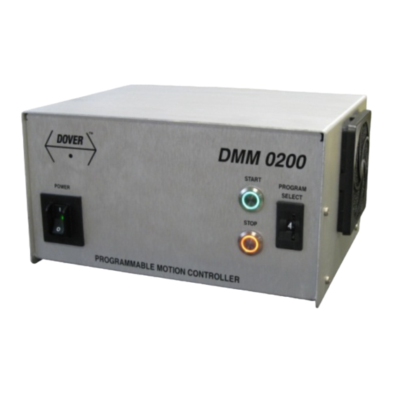
Page 22: Front Panel
Page 22 of 112 DMM-0200 Product User Guide Front Panel Figure 3 DMM-0200 Front View Item Function Description POWER On/Off power switch START Start motion program STOP Stop motion program PROGRAM SELECT Selects the motion program number ... -
Page 23: Rear Panel
Fuse X, Y Fuse LED X, Y Axis Y J19-ANALOG I/O JOYSTICK J18-DIGITAL I/O JP1 – JP8 AC IN J36-ENC OUT X/Y Axis X Figure 4 DMM-0200 Rear View 159 Swanson Road Boxborough, MA 01719 Tel: 508-475-3400 Email: sales@dovermotion.com... -
Page 24: Rear Panel Connectors & Switches
Page 24 of 112 DMM-0200 Product User Guide Rear Panel Connectors & Switches The following table lists the connector positions on the rear panel and the type of connector for each. Table 5 Rear Panel Connectors Connector Position Description Connector Type... -
Page 25: Rear Panel Connector Pinouts
+5VDC Data- Data+ Ground Table 8 Pinouts – USB Communication Note: The user should only need to communicate to the DMM-0200 using the USB connection. The USB connection provides full control of the DMM-0200. 159 Swanson Road... -
Page 26: Table 9 Pinouts - Encoder/Limits
Page 26 of 112 DMM-0200 Product User Guide Pinouts – Encoder/Limits (J10-ENC/LIM X, J24-ENC/LIM Y) Pin Number Function Description HD-15-F Connector +VLIM Limit power (+5VDC) +LIM Positive limit -LIM Negative limit CHASSIS Earth ground Logic ground +5VENC Encoder power (+5VDC) -
Page 27: Table 11 Pinouts - Encoder Out X & Y
Page 27 of 112 DMM-0200 Product User Guide Pinouts – Encoder Out X & Y (J25-ENC OUT X/Y) Pin Number Function Description DA-15-M Connector Y axis – Encoder A channel ENC AY Y axis – Encoder /A channel ENC /AY Y axis –... -
Page 28: Table 13 Pinouts - Analog I/O & Joystick
Page 28 of 112 DMM-0200 Product User Guide Pinouts – Analog I/O & Joystick (J19-ANALOG I/O JOYSTICK) Pin Number Function Description DA-15-F Connector +VANALOG Analog power (+5VDC) STICK P/B Joystick - Stick pushbutton, Digital input 1 ANALOG X Joystick X analog input, Analog input 1... -
Page 29: Rear Panel Jumper And Switch Selection
Page 29 of 112 DMM-0200 Product User Guide Rear Panel Jumper and Switch Selection Current Switch Settings – SW1 CUR X, SW2 CUR Y Current (A) DIP Switch Table 14 Current Switch Settings These DIP switches set the maximum current rating for the stepper motor. Please refer to your motor data sheet to set these DIP switches. -
Page 30: Table 15 Jumper Selection-Jp1 - Jp8
Page 30 of 112 DMM-0200 Product User Guide Jumper Selection – JP1 – JP8 I/O Config with Cover I/O Config without Cover Jumper Function Description Installing a jumper on will the SPDT Relay JP1 1-2 disable 1-2 for Output 8 to rear panel... -
Page 31: Rear Panel Leds
Page 31 of 112 DMM-0200 Product User Guide Rear Panel LEDs Fuse LEDs Description Possible States Fuse X Indicates that the fuse on X Not illuminated Fuse is blown axis is ok Illuminated green No error Fuse Y Indicates that the fuse on Y... -
Page 32: Interface Circuitry
Page 32 of 112 DMM-0200 Product User Guide Interface Circuitry Limit, Home, and Digital Input To trigger the opto-isolated digital inputs, sink the digital input signal to the ground of the corresponding opto-supply. VS Opto-Supply (+5VDC) Note: Alarm input for TB9 version is 5V TTL type. -
Page 33: Encoder Input Connection
The maximum encoder frequency is 5MHz. Figure 7 Encoder Inputs Analog Inputs 8 x 10-bit analog inputs are available on the DMM-0200. Use AI[1-8] command to read the analog input value. Range is from 0-5000 mV. Figure 8 Analog Inputs ... -
Page 34: Where To Go Next
Continue with the next chapter, Chapter 3 - Insta ing the DMM-0200. Now that user has become familiar with the technical capabilities of the DMM-0200, the next section will outline the steps needed to install the DMM-0200 into your system. ... -
Page 35: Chapter 3 -Installing The Dmm-0200
Page 35 of 112 DMM-0200 Product User Guide Chapter 3 Installing the DMM-0200 About This Chapter Introduction This chapter describes how to hook up the DMM-0200 to your Dover Motion stages. Topics This chapter covers the following topics: Topic Page Installing the System... -
Page 36: Installing The System
Figure 9 System Installation Modes of Operation PC Controlled – The DMM-0200 can be controlled using a PC and USB communications. Dover Motion provides a GUI for running and programming the DMM-0200. The software is called PMX-2EX-SA. See Chapter 5. -
Page 37: Connecting To The Dmm-0200
Installing the Power Cord and Communications Cables The DMM-0200 comes with a 2.4 meter (approx. 8 foot) power cord. You must supply the USB 2.0 cable. To install the power cord, insert the female connector on the power cord into the male receptacle on the rear of the system enclosure. -
Page 38: Where To Go Next
DMM-0200. The next section describes the steps needed to properly install the application software. Note: Using the PMX-2EX-SA Software is not required in order to communicate to the DMM-0200. The user may use Labview, Matlab, or a number of other software to communicate to the DMM-0200 through USB connection. -
Page 39: Chapter 4 - Installing Application Software For The Dmm-0200
DMM-0200 Product User Guide Chapter 4 Installing Application Software for the DMM-0200 About This Chapter Introduction This chapter describes the Application GUI software you need to run the DMM-0200 via a terminal. Topics This chapter covers the following topics: Topic Page... -
Page 40: Software Description
DMM-0200 Product User Guide Software Description The software that is used to communicate and to run the DMM-0200 is the PMX-2EX-SA software. This software provides the user with an intuitive graphical user interface for running and programming the DMM-0200. The user also needs to install the PMX drivers to complement the software. -
Page 41: Installing Pmx Drivers
Page 41 of 112 DMM-0200 Product User Guide Installing PMX Drivers Locate the CD that was shipped with your DMM-0200. From your Windows folder double click the “Arcus_Drivers_and_Tools_Setup_1.06” and follow the on screen instructions. See Figure 11. Figure 11 Driver Installation ... -
Page 42: Where To Go Next
Where to Go Next Continue with the next chapter, Chapter 5 - Running the DMM-0200 via PMX-2EX-SA Software. This next section describes how to use the software that was installed in section 4. Details and functions about the various screens are described. -
Page 43: Chapter 5 - Running The Dmm-0200 Via Pmx-2Ex-Sa Software
Running the DMM-0200 via PMX-2EX-SA Software About This Chapter Introduction This chapter describes how to communicate with the DMM-0200 via USB connection to the user’s PC and how to use the PMX-2EX-SA software to control motion. Topics This chapter covers the following topics:... -
Page 44: Connecting A Usb Cable
DMM-0200 Product User Guide a USB Cable Connecting To communicate with the DMM-0200 via a terminal you will need a USB 2.0 cable not supplied with this DMM. See Table 3 for details of cable specifications. Once you have located a USB cable, plug the “B” end into the DMM-0200 USB port. See 12 . -
Page 45: Establishing Communication With The Dmm-0200
Establishing Communication with the DMM-0200 Locate the “SOFT-EXE-PMX-2EX-SA-114” icon on your desktop or locate it in your START menu. Figure 13 PMX-2EX-SA Application Select the device you what to communicate with. Choose USB for USB communications for the DMM-0200. ... -
Page 46: Using The Main Control Screen
Using the Main Control Screen With the DMM-0200 GUI, you can control all motion via one “Main Control Screen”, see Figure 14. For addition information not found in this manual reference the “PMX-4EX-SA Manual” which is included on the shipping CD and installed onto your PC with this GUI. -
Page 47: Status Screen (A)
Page 47 of 112 DMM-0200 Product User Guide Status Screen (A) Figure 15 Status Screen (A) 1. Current pulse position (X/Y axis). 2. Current encoder position (X/Y axis). 3. Current speed (X/Y axis). 4. Motor status (X/Y axis). IDLE – Motor is not moving. -
Page 48: Control (B)
Page 48 of 112 DMM-0200 Product User Guide Control (B) Figure 16 Status Screen (B) Global high speed, low speed, and acceleration values are entered here (X/Y axis). To give each axis individual speed parameters, enter HSPD[axis], LSPD[axis], and ACC[axis] into the command line in the “Terminal” section. -
Page 49: Product Information (D)
Page 49 of 112 DMM-0200 Product User Guide Product Information (D) Figure 18 Product Information (D) Terminal (E) Figure 19 Terminal (E) 1. Send commands to the PMX-2EX-SA through this terminal 2. Replies from the PMX-2EX-SA will be shown here. -
Page 50: About (H)
Page 50 of 112 DMM-0200 Product User Guide About (H) Figure 22 About (H) Displays the current software and firmware versions Setup (I) Polarity: Set direction/pulse/home/Z-index polarity for X/Y axis Set s-curve enable/disable for X/Y axis Set the encoder multiplier to 1X/2X/4X for X/Y axis... -
Page 51: Variables (J)
Page 51 of 112 DMM-0200 Product User Guide 2. Boot Up a. DO Boot/EO Boot - Set the digital and enable output configuration on boot up b. Auto Run - Have the specified standalone program run on boot up. 3. Homing Parameters a. -
Page 52: Program File Control (K)
Page 52 of 112 DMM-0200 Product User Guide Program File Control (K) Figure 25 Program File Control (K) Open - Open a standalone program Save - Save a standalone program New - Clear the standalone program editor Text Programming Box (L) Figure 26 Text Programming Box (L) Text Program –... -
Page 53: Compiler (M)
Page 53 of 112 DMM-0200 Product User Guide Compiler (M) Figure 27 Compiler (M) Compile - Compile code in text programming box into assembly level code that the PMX-2EX-SA can understand. Download - Download the compiled code into memory. Note that the text based code must be compiled before download. -
Page 54: Where To Go Next
Chapter 6 - Running the DMM-0200 via Front Panel Buttons. The next section describes how to run the DMM-0200 in standalone mode using the front panel buttons to control motion. Descriptions of the default motion programs installed on the DMM-0200 are also described. -
Page 55: Chapter 6 - Running The Dmm-0200 Via Front Panel Buttons
About This Chapter Introduction This chapter describes how to run the DMM-0200 via the Front Panel Thumb Wheel and Start/ Jog+, Stop/ Jog- buttons for standalone operation. The sample motion programs installed from the factory are also described in greater detail. -
Page 56: Front Panel Buttons
Figure 29. These buttons can be used to run stored programs in the DMM-0200s memory. No USB communication to the DMM-0200 is required for standalone operation. The DMM-0200 will function as a completely standalone motion controller. Figure 29 DMM-0200 Front Panel ... -
Page 57: Dmm-0200 Stored Programs
Page 57 of 112 DMM-0200 Product User Guide DMM-0200 Stored programs The DMM-0200 is shipped with 7 standard programs that can be executed via the Thumbwheel and Start/ Stop buttons. See Table 18. Note: The programs shipped with the DMM-0200 are SAMPLE programs. These programs are not intended to be the customer’s final solution. -
Page 58: Where To Go Next
Continue with the next chapter, Chapter 7 - Editing Programs. Using either front panel buttons or the application software to control the DMM-0200, the DMM-0200 calls motion programs to run the stages. The next section describes how to edit those programs. ... -
Page 59: Chapter 7 - Editing Programs
Chapter 7 Editing Programs About This Chapter Introduction This chapter describes how to edit motion programs with the GUI. This chapter also describes the programming language for programs in the DMM-0200 Topics This chapter covers the following topics: Topic Page... -
Page 60: Editing A Stored Program
Page 60 of 112 DMM-0200 Product User Guide Editing a Stored Program To edit a stored program with the GUI, you first need to open the program. You can either Upload the program from the controller’s memory or open a program saved on your PC. Within the GUI you can hit the Open or Upload button. See Figure 30. -
Page 61: Figure 31 Text Window
If you want to keep Dover Motion’s standard programs, you will have to edit the uploaded file (which contains Dover Motion’s standard programs) to include your new motion programs. If you do not want to keep Dover Motion’s standard programs, Clear Code Space, create your own motion programs, and download to the controller’s memory ... -
Page 62: Standalone Program Specification
Page 62 of 112 DMM-0200 Product User Guide Standalone Program Specification Standalone Program Specification: Memory size: 1,275 assembly lines. Note: Each line of pre-compiled code equates to 1-4 lines of assembly lines. WAIT Statement When writing a standalone program, it is generally necessary to wait until a motion is completed before moving on to the next line. -
Page 63: Table 19 Standalone Run On Boot-Up
Page 63 of 112 DMM-0200 Product User Guide Standalone Run on Boot-Up Standalone can be configured to run on boot-up using the SLOAD command. See description below: Description Standalone Program 0 Standalone Program 1 Table 19 Standalone Run on Boot-Up... -
Page 64: Programming Language Specification
Page 64 of 112 DMM-0200 Product User Guide Programming Language Specification Description: Comment notation. In programming, comment must be in its own line. Syntax: ; [Comment Text] Examples: ; ***This is a comment JOGX+ ;***Jogs X axis to positive direction DELAY= 1000 ;***Wait 1 second... - Page 65 Page 65 of 112 DMM-0200 Product User Guide Description: Get acceleration value Read: Set acceleration value. Write: Value is in milliseconds. Range is from 1to 10,000 Syntax: Read: [variable] = ACC Write: ACC = [value] ACC = [variable] Conditional: IF ACC=[variable]...
- Page 66 Page 66 of 112 DMM-0200 Product User Guide Description: Read: Get deceleration value Write: Set deceleration value Value is in milliseconds. Syntax: Read: [variable] = DEC Write: DEC = [value] DEC = [variable] Examples: DEC=300 ;***Sets the deceleration to 300 milliseconds V3=500 ;***Sets the variable 3 to 500...
- Page 67 Page 67 of 112 DMM-0200 Product User Guide Read: [variable] = DI Conditional: IF DI=[variable] ENDIF IF DI=[value] ENDIF Examples: IF DI=255 DO= 1 ; * * *If no digital inputs are triggered, set DO= 1 ENDIF DI(1-8J Description: Read: Gets the digital input value...
- Page 68 Page 68 of 112 DMM-0200 Product User Guide DO[1-8] = [variable] Conditional: IF DO[1-8]=[variable] ENDIF IF DO[1-8]=[0 or 1] ENDIF Examples: DO7=1 ;***Turn DO7 on DO6=1 ;***Turn DO6 on E[axis] Description: Gets the current encoder position Read: Write: Sets the current encoder position...
- Page 69 Page 69 of 112 DMM-0200 Product User Guide X-1000 ;***If V1 is not 1, then move to - 1000 WAITX ENDIF ELSEIF Description: Perform ELSEIF condition check as a part of the IF statement Syntax: ELSEIF [Argument 1] [Comparison] [Argument 2]...
- Page 70 Page 70 of 112 DMM-0200 Product User Guide ENDIF Description: Indicates end of IF operation Syntax: ENDIF Examples: IF V1=1 X1000 WAITX ENDIF ENDSUB Description: Indicates end of subroutine When ENDSUB is reached, the program returns to the previously called subroutine.
- Page 71 Page 71 of 112 DMM-0200 Product User Guide ENDIF IF EO= [value] ENDIF Examples: EO=3 ;***Turn first 2 bits of enable outputs IF V1=1 EO=V2 ;***Enable output according to variable 2 ENDIF EO[1-2J Description: Read: Gets the individual enable output value Write: Sets the individual enable output value Performax 2EX has 2 enable outputs.
- Page 72 Page 72 of 112 DMM-0200 Product User Guide HLHOMEX+ ;***Low speed homes X axis in positive direction WAITX HLHOMEY- ;***Low speed homes Y axis in negative direction WAITY HSPD Description: Read: Gets high speed. Value is in pulses/second Write: Sets high speed. Value is in pulses/second.
- Page 73 Page 73 of 112 DMM-0200 Product User Guide Pulse or Encoder Position Digital Output Digital Input Enable Output Motor Status [Comparison] can be any of the following Equal to > Greater than < Less than >= Greater than or equal to <=...
- Page 74 Page 74 of 112 DMM-0200 Product User Guide Set high speed setting for joystick control Write: Syntax: Write: JOYHS [axis] = [value] JOYHS [axis] = [variable] Examples: JOYHSX=10000 ;***High speed of X axis is set to 10,000 pps JOYHSY=20000 ;***High speed of Y axis is set to 20,000 pps...
- Page 75 Page 75 of 112 DMM-0200 Product User Guide JOYPO[axis] Description: Set positive outer limit for joystick control Write: Syntax: Write: JOYPO[axis] = [value] JOYPO[axis] = [variable] Examples: See JOYNO[axis] JOYTOL[axis] Description: Write: Set zero tolerance value for joystick control Syntax:...
- Page 76 Page 76 of 112 DMM-0200 Product User Guide Write: LSPD[axis]=[long value] LSPD[axis]=[variable] Conditional: IF LSPD[axis]=[variable] ENDIF IF LSPD[axis]=[value] ENDIF Examples: LSPDZ=1000 ;***Sets the Z low speed to 1,000 pulses/sec V 1=500 ;***Sets the variable 1to 500 LSPDZ=V1 ;***Sets the Z low speed to variable 1 value of 500...
- Page 77 Page 77 of 112 DMM-0200 Product User Guide X8000 PRG 1 ;***Program 1 Y1000 PS[axis] Description: Read: Get the current pulse position of an axis Syntax: Read: Variable = PS[Axis] Conditional: IF PS[axis]=[variable] ENDIF IF PS[axis]=[value] ENDIF Examples: JOGX+ ;***Jogs X axis to positive direction DELAY= 1000 ;***Wait 1 second...
- Page 78 Page 78 of 112 DMM-0200 Product User Guide Description: Command: Get the StepNLoop status of axis Syntax: SLS [Axis] V[Value] = SLS [Axis] Examples: IF SLSX=0 DIO=6 ELSEIF SLSY=0 DIO=3 ENDIF SR[0,1] Description: Write: Set the standalone control for the specified standalone program...
- Page 79 Page 79 of 112 DMM-0200 Product User Guide JOGX+ ;***Jogs X axis to positive direction DELAY= 1000 ;***Wait 1 second SSPDMX=1 ;***Set on-the-fly speed change mode to 1 ACCX=20000 ;***Set acceleration to 20 seconds SSPDX=190000 ;***Change speed on X-axis on-the-fly to 190000 PPS...
- Page 80 Page 80 of 112 DMM-0200 Product User Guide GOSUB 1 SUB 1 WAITX X1000 WAITX ENDSUB Description: Sets the communication time-out parameter. Value is in milli-seconds. Syntax: TOC=[long value] Examples: TOC=10000 ;***Sets time-out parameter to 10 seconds Description: Assign to variable. Performax 2EX has 64 variables [V0-V63]...
- Page 81 Page 81 of 112 DMM-0200 Product User Guide WAIT Description: Tell program to wait until move on the certain axis is finished before executing next line. Syntax: WAIT[axis] X[variable] Examples: X10000 ;***Move X Axis to position 10000 WAITX ;***Wait until X Axis move is done DO=5 ;***Set digital output...
- Page 82 Page 82 of 112 DMM-0200 Product User Guide X10000 ***MoveXAxistoposition 10000 WAITX X2000Y3000 ;***MoveXto2000andYto3000inlinearinterpolationmove WAITX V10 = 1200 ;***Set variable 10 value to 1200 XV10 ;***Move X Axis to variable 10 value WAITX Description: Perform Y axis move to target location Command: With other Axis moves in the same line, linear interpolation move is done.
-
Page 83: Sample Programs
Page 83 of 112 DMM-0200 Product User Guide Sample Programs Standalone Example Program 1 –Single Thread Task: Set the high speed and low speed and move the motor to 1000 and back to 0. HSPD=20000 ;* Set the high speed to 20000 pulses/sec LSPD=1000 ;* Set the low speed to 1000 pulses/sec... - Page 84 Page 84 of 112 DMM-0200 Product User Guide Standalone Example Program 4 –Single Thread Task: Move the motor back and forth between position 1000 and 0 only if the digital input 1 is turned on. HSPD=20000 ;* Set the high speed to 20000 pulses/sec LSPD=1000 ;* Set the low speed to 1000 pulses/sec...
- Page 85 Page 85 of 112 DMM-0200 Product User Guide IF DI1=1 ;*Ifdigitalinput1 ison X1000 ;*Moveto 1000 WAITX ;* Wait for X-axis move to complete ELSEIF DI2=1 ;* If digital input 2 ison X2000 ;* Move to 2000 WAITX ;* Wait for X-axis move to complete ELSEIF DI3=1 ;* If digital input 3 ison...
- Page 86 Page 86 of 112 DMM-0200 Product User Guide Standalone Example Program 8 –Multi Thread Task: Program 0 will continuously move the motor between positions 0 and 1000. Simultaneously, program 1 will monitor the communication time-out parameter and triggers digital output 1 if a time-out occurs. Program 1 will also stop all motion, disable program 0 and then re-enable it after a delay of 3 seconds when the error occurs.
-
Page 87: Where To Go Next
Chapter 8 - Interactive Commands & USB Communications. Previous sections described how to use the PMX-2EX-SA software to communicate to the DMM-0200. Section 8 describes the basic ASCII commands and USB communications when using some other software such as Matlab or Labview. -
Page 88: Chapter 8 -Interactive Commands & Usb Communications
About This Chapter Introduction This chapter describes the USB communications and ASCII commands in detail to communicate to the DMM-0200. Previous sections explain the communication with the PMX-2EX-SA software. The user does not necessarily need to use the PMX-2EX-SA software to communicate to the DMM-0400. Visual BASIC, Visual C++, Labview, Matlab or other software can communicate to the DMM-200 through the USB connection. -
Page 89: Usb Communication Description
Page 89 of 112 DMM-0200 Product User Guide USB Communication Description PMX-2EX-SA USB communication is USB 2.0 compliant. Communication between the PC and PMX-2EX-SA is done using Windows compatible DLL API function calls as shown below. Windows programming language such as Visual BASIC, Visual C++, LAB View, or any other programming language that can use DLL can be used to communicate with the Performax module. -
Page 90: Figure 32 Usb Cable
Page 90 of 112 DMM-0200 Product User Guide USB Communication Issues A common problem that users may have with USB communication is that after sending a command from the PC to the device, the response is not received by the PC until another command is sent. In this case, the data buffers between the PC and the USB device are out of sync. -
Page 91: Motion Control Overview And Interactive Command Description
Page 91 of 112 DMM-0200 Product User Guide Motion Control Overview and Interactive Command Description All the commands described in this section are interactive commands and are not analogous to stand-alone commands. Refer to the “Standalone Language Specification” section for details regarding stand-alone commands. -
Page 92: Table 21 Pulse Speed
Page 92 of 112 DMM-0200 Product User Guide Example: To set the high-speed of the X-axis to 1500 pulses/second, and the Y- axis to 2000 pulses/second, issue the following speed setting commands: ‘ set high speed for x-axis only HSX=1500 ‘... -
Page 93: Table 22 Motor Status
Page 93 of 112 DMM-0200 Product User Guide Motor Status Motor status can be read anytime using command. Value of the motor status is replied as an MSTX/MSTY integer with following bit assignment: Description Motor in acceleration Motor in deceleration... -
Page 94: Figure 35 Homing - Home Input Only (High Speed)
Page 94 of 112 DMM-0200 Product User Guide On-The-Fly Target Position Change On-the-fly target position change can be achieved using the T[axis][value] command. While the motor is moving, T[axis][value] will change the final destination of the motor. If the motor has already passed the new target position, it will reverse direction once the target position change command is issued. -
Page 95: Figure 37 Homing - Limit Only
Page 95 of 112 DMM-0200 Product User Guide A. Starts the motor from low speed and accelerates to high speed. B. As soon as the home input is triggered, the position counter is reset to zero and the motor decelerates to low speed. -
Page 96: Figure 38 Homing - Home And Z-Index
Page 96 of 112 DMM-0200 Product User Guide Figure 38 Homing - Home and Z-Index Issuing the command starts the motor from low speed and accelerates to high speed. As soon as the home input is triggered, the motor decelerates to low speed. -
Page 97: Table 23 Polarity
Page 97 of 112 DMM-0200 Product User Guide Motor Position Motor positions can be read usingthe PX/PY command which returns the pulse position of the specified axis. Encoder positions can be read using EX/EY command which returns the encoder position of the specified axis. -
Page 98: Table 24 Digital Inputs
Page 98 of 112 DMM-0200 Product User Guide Digital Inputs/Outputs and Enable Outputs PMX-2EX-SA module comes with 8 digital inputs and 8 digital outputsand 4 enable outputs. Inputs Read digital input status using the DI command. Digital input values can also be referenced one bit at a time by the DI[1-8] commands. Note that the indexes are 1-based for the bit references (i.e. -
Page 99: Table 26 Enable Outputs
Page 99 of 112 DMM-0200 Product User Guide Enable Outputs The enable output status can be controlled using the EO command. EO value must be within the range of 0-3. Enable output values can also be referenced one bit at a time by the EO[1-2J commands. -
Page 100: Table 28 Summary Of Joystick Control Parameters
Page 100 of 112 DMM-0200 Product User Guide Summary of Joystick Control Parameters Parameter Description X-axis maximum joystick speed at 5000 mV and 0 mV Y-axis maximum joystick speed at 5000 mV and 0 mV X-axis maximum speed change Y-axis maximum speed change... -
Page 101: Table 29 Stepnloop Closed Loop Control
Page 101 of 112 DMM-0200 Product User Guide Maximum error between target and actual position that is not considered a serious error. If the error exceeds Error Range SLE[axis] this value, the motor will stop immediately and go into an error state. -
Page 102: Table 31 Stepnloop Conditions
Page 102 of 112 DMM-0200 Product User Guide Table 31 for SNL behavior within different scenarios. SNL behavior SNL behavior Condition (motor is moving) (motor is idle) In Position. No correction is Continue to monitor the DX[axis] <= SLT performed. -
Page 103: Ascii Programming Language
Page 103 of 112 DMM-0200 Product User Guide ASCII Programming Language Invalid command is returned with ?(Error Message). Always check for proper reply when command is sent. Like the commands, all responses are in ASCII form. Table 32 ASCII Commands... - Page 104 Page 104 of 112 DMM-0200 Product User Guide Command Description Return GS[SubNumber] Call a defined subroutine Returns the global home correction amount 28-bit number HCA=[Value] Sets the global home correction amount. HCAX HCAY Returns the home correction amount for the specified axis.
- Page 105 Page 105 of 112 DMM-0200 Product User Guide LCAX=[value] Sets the specified limit correction amount LCAY=[value] Command Description Return LSPD Returns the global low speed setting 32-bit number LSPD=[Value] Sets the global low speed setting. LSPDX Returns low speed setting for the X-axis and Y-axis...
- Page 106 Page 106 of 112 DMM-0200 Product User Guide SLEX=[value] Sets StepNLoop correction value. SLEY=[value] SLRX Returns StepNLoop ratio value 32-bit number SLRY Command Description Return SLRX=[factor Sets StepNLoop ratio value. SLRY=[factor SLSX Returns current status of StepNLoop control Table 30...
-
Page 107: Error Codes
Page 107 of 112 DMM-0200 Product User Guide Y[Value] Individual move command. If in ABS mode, move to position value. If in INC mode, increase position by value. Homes both X and Y axis using the Z-index in the positive direction OK... -
Page 108: Where To Go Next
Page 108 of 112 DMM-0200 Product User Guide Where to Go Next The user should now have all the information required to run the DMM-0200. If any further assistance is required, please contact the service department at Dover Motion. ... -
Page 109: Appendix
Page 109 of 112 DMM-0200 Product User Guide Appendix About This Chapter Introduction This appendix contains supporting information for the DMM-0200. Topics This chapter covers the following topics: Topic Page Speed Settings Acceleration/Deceleration Range Acceleration/Deceleration Range – Positional Move Review/Revision History ... -
Page 110: Speed Settings
Page 110 of 112 DMM-0200 Product User Guide Speed Settings Table 34 Speed Settings Speed Min. HSPD value Min. ACC Window LSPD δ Max ACC setting [ms] [PPS] † [ms] [SSPDM] value 1 - 16K 16k - 32K 32K - 80K 1,900 ((HSPD –... -
Page 111: Acceleration/Deceleration Range
Page 111 of 112 DMM-0200 Product User Guide Acceleration/Deceleration Range – Positional Move When dealing with positional moves, the controller automatically calculates the appropriate acceleration and deceleration based on the following rules. Figure 41 Acceleration/Deceleration Profile ACC vs. DEC 1: If the theoretical position where the controller begins deceleration is less than L/2, the acceleration value is used for both ramp up and ramp down. - Page 112 Page 112 of 112 DMM-0200 Product User Guide Review/Revision History Revision Date Summary ECO Number Writer/ Reviser 09/14/12 Initial Release Phil Li 3/11/13 Removed servo references S04_101116 Phil Li 06/18/13 Added Switch silkscreen S04_101185 Robert Winslow update (PG23). Changed table 14 from 0 and 1 to up/down.
Need help?
Do you have a question about the DMM-0200 and is the answer not in the manual?
Questions and answers