Table of Contents
Advertisement
Advertisement
Table of Contents
Troubleshooting

Related Manuals for Savch S900 Series


Summary of Contents for Savch S900 Series
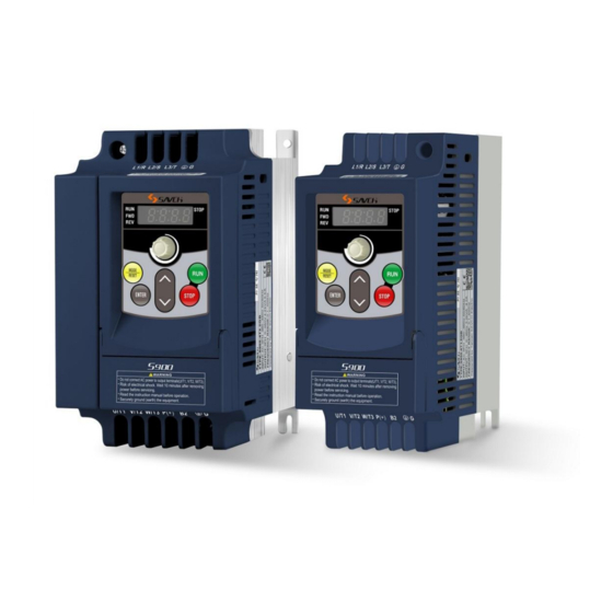
- Page 1 S900 Series Inverter Multi Function Mini Type (IM) User Manual User Manual...
- Page 2 520000009075 Vision No. V1.5 Filing time 2020-11-16 SAVCH electric provide a full range of technical support for our customers. All users could contact with the nearest SAVCH office or service center, also could contact with our headquarters directly. SAVCH Electric reserves the copyrights and all rights,...
-
Page 3: Table Of Contents
Contents PREFACE................................1 Ⅰ.SAFETY INSTRUCTIONS ........................... 2 1. NOTES FOR OPERATION ............................... 2 2. NOTES FOR OPERATION ENVIRONMENT ........................ 4 Ⅱ. DESCRIPTIONS FOR BODY AND INSTALLATION ..................5 1. OPERATION ENVIRONMENT ............................5 2. MODEL DESCRIPTION ..............................6 4. LIST OF APPLICABLE NO-FUSE BREAKER ......................9 5. -
Page 4: Preface
PREFACE Thanks for your use of SAVCH inverter! This instruction manual, which includes operation descriptions and notes for maintenance, shall be delivered to the end-user. For safety running and effective operation, this instruction manual shall be read thoroughly prior to use, which shall also be preserved for later use. -
Page 5: Ⅰ.safety Instructions
Ⅰ.SAFETY INSTRUCTIONS 1. NOTES FOR OPERATION Before wiring CAUTION ● Specification of applying power supply shall correspond to input voltage of the inverter. WARNING ● Main circuit terminals must be correct, L1/R, L2/ S and L3/ T is input terminals and it’s forbidden to use mixing with U, V and W. - Page 6 During check and maintenance CAUTION ● Ambient temperature for operating the inverter shall be -10℃ to + 50℃ (+40℃ parallel installation) and 90%RH no condensation. However under this condition, the ambient environment must be without drips of water or metal dust. During Disposal CAUTION ●...
-
Page 7: Notes For Operation Environment
2. NOTES FOR OPERATION ENVIRONMENT Do not use the inverter in an environment with the following conditions:... -
Page 8: Ⅱ. Descriptions For Body And Installation
Ⅱ. DESCRIPTIONS FOR BODY AND INSTALLATION 1. OPERATION ENVIRONMENT Since operation environment can directly influence functions and operation life, to ensure proper performance and long operation, follow the recommendations below when choosing allocation for installing the inverter. Make sure it is protected from the following: Extreme cold and heat. -
Page 9: Model Description
Model TYPE:S900-4T1.5G INPUT:AC 3PH 380~460V 50/60Hz Input power supply Spec. Output power supply Spec. OUTPUT:3PH 0~460V 3.2KVA 4.2A FREQUENCYRANGE:0.1~400Hz Output frequency Designed by Taiwan Savch Electric 900 - 4T B:Inverter Model with built-in brake resistor SAVCH 0.2:0.2kW Product 2S:220V G:Constant torque... - Page 10 3. SPECIFICATIONS Product Specifications ■ 200V Single Phase Series Model number S900-2S□□□G 0.75 Max applicable motor output power(kW) 0.75 Max applicable motor output power(HP) 0.25 Output rated capacity(kVA) Output rated current (A) Output frequency range 0.1 to 400Hz Over load capacity 150% of rated output current and run for 60sec.
- Page 11 ■ Standard Specifications Control mode Adopting SVPWM or SPWM modulating techniques Output frequency range 0. 1 to 400Hz Frequency setting analyzing degree 0.1Hz Output frequency analyzing degree 0.1Hz PWM carrier frequency Available to modulate from 2 to 12kHz. Auto torque-increase and auto slip compensation, at 5Hz the Torque increase starting torque can reach 150% of rated torque.
-
Page 12: List Of Applicable No-Fuse Breaker
(0.6g) Protection level IP20 SAVCH ELECTRIC shall not be responsible for faults due to the following: (1) Absence or inapplicable or over large non-fuse breakers was put between the power supply and the inverter, which results in the inverter fault. -
Page 13: Application And Description For Ambient Equipments
5. APPLICATION AND DESCRIPTION FOR AMBIENT EQUIPMENTS Power supply: ●Make sure voltage class is correct, otherwise inverter may be damaged. Power supply ●A no fuse breaker (air circuit breaker) shall be provided between AC supply and inverter. No fuse Breaker: No fuse Breaker ●Circuit breaker which complies with rated voltage and current of inverter shall be applied as ON/OFF control for inverter. - Page 14 Wiring shall be checked whether correct or not. Peripheral wiring shall fulfill the following requirements. (Do not use a buzzer of control circuit to check wiring) (A) Wiring for control circuit Power supply must be isolated or far from other high voltage wirings or high current power lines, thus electromagnetic interference can be avoided.
- Page 15 ● Voltage drop of wiring shall be considered providing that inverter and motor are with an excessive distance. × wiring resistance (Ω/km) × wire length (m) × current (A) × 10 Voltage drop (V) = , carrier frequency shall be modified according to wiring prepared.
-
Page 16: Basic Wiring Diagram
Wiring of AC motor drive can be divided into two parts, the main circuit and control circuit. Users must connect terminals as diagram shows. The following diagram is the standard wiring diagram of S900 series AC motor driver. Note: RS485 may damage the terminal of connector side. So the terminal configuration has to be confirmed before... - Page 17 Description for S900 Series Inverter Terminals Main circuit terminal descriptions Terminal symbols Function L1/R,L2/S,L3/T Main circuit AC power supply input(For single phase input, connect to L1/L and L2/N) U,V,W Connect to motor (+), (-) Connect to braking module For grounding (High voltage wave impact and noise interference shall be avoided.)
-
Page 18: External Dimensions
7. EXTERNAL DIMENSIONS Figure 7-1 Dimension and installation size of S900-2S0.2G~0.75G/S900-4T0.4G -1.5G (unit: mm) Figure 7-2 Dimension and installation size of S900-2S1.5G~2.2G/S900-4T2.2G -3.7G (unit: mm) -
Page 19: Ⅲ. Description Of Operation Panel
Ⅲ. DESCRIPTION OF OPERATION PANEL 1. DESCRIPTION FOR DIGITAL OPERATION PANEL The digital operation panel has two spaces: display space and operating space. Parameters setting and different operation states shall be displayed on the display space, while for the operating space, it is an interface for communication of the operators and AC motor inverter. - Page 20 Description of indicator light RUN Operation indicator light: it will light on when the inverter is in operation state. STOP Stop indicator light:: it will light on when the inverter is in stop state. FWD Forward indicator light: it will light on when the rotating direction of inverter is forward. REV Reverse indicator light: it will light on when the rotating direction of inverter is reversal.
-
Page 21: Description Of Paneloperation
2. DESCRIPTION OF PANELOPERATION Scenes Selection Configuration Setup Data Modification Steering Setup... -
Page 22: Preliminary Operation-Not Connecting With Motor
3. PRELIMINARY OPERATION-NOT CONNECTING WITH MOTOR ● Prior to connecting power supply with inverter, check and make sure that AC power supply voltage is within input voltage range of the inverter. ● Connect power supply to L1/R,L2/S and L3/T input terminals of the inverter. ●... - Page 23 □ 3-wire operation control mode Configuration 1 (2-03=d1, 4-04=d3) STOP REV/FWD □ 3-wire operation control mode Configuration 2 (2-03=d1, 4-04=d4) FWD/RUN REV/RUN STOP □ Operation command is controlled by communication (2-03=d3/d4 [STOP key valid/invalid]) RS485 PC/PLC Interface...
-
Page 24: Ⅳ. List Of Descriptions For Functional Parameters
Ⅳ. LIST OF DESCRIPTIONS FOR FUNCTIONAL PARAMETERS 0. User’s parameters set during running available Parame Factory Parameter functions Setting range setting 1:200V/0.2kW 2:200V/0.4kW 3:200V/0.75kW 4: 200V/1.5kW 5: 200V/2.2kW Inverter type code recognition (Only Factory 0-00 6 to 9: Reserved for Reading) setting 10:400V/0.4kW... - Page 25 0. User’s parameters set during running available Parame Factory Parameter functions Setting range setting 0-09 Reserved Parameters marked with “reserved” will be displayed, but will not be used for the inverter. Please do not change the code of such kind of parameter. ...
- Page 26 Set during running available 2. Operation mode parameters Parame Factory Parameter functions Setting range setting 0:Keys on keypad 1:Input DC 0 to 10V by external terminals AVI 2:Input 4 to 20mA by external terminals ACI 3:controlled by VR on keypad 2-01 Frequency command 2 4:Reserved...
- Page 27 Notes: 1)In 2-00 and 2-01, when 2-00 has been set as d1(AVI) or d2(ACI), 2-01 can't be set as d1 or d2 again. 2)In 2-00 and 2-01, when 2-00 has been set as d6 or d7 (controlled by UP/DOWN), 2-01 can't be set as d6 or d7 again.
- Page 28 Set during running available 3. Output Function Parameters Parame Factory Parameter functions Setting range setting 0: No function 1: Inverter running 2: Frequency arrival 3: Zero speed 4: Over-torque detection 5: During external alarm 6. Low voltage detection 7: External terminal running mode 8: Alarm output (for any alarm) 9: Frequency detection 3-09...
- Page 29 Set during running available 4. Input Function Parameters Paramet Factory Parameter functions Setting range setting 4-00 [VR] Input frequency bias setting 0.0 to 350Hz [VR] Input frequency bias adjustment 0: Positive direction 4-01 direction 1: Negative direction ...
- Page 30 Set during running available 4. Input Function Parameters Paramet Factory Parameter functions Setting range setting 0:Tracking downwards from speed before Speed tracking after external alarm 4-09 external alarm reset 1:Tracking upwards from min speed 4-10~4.22 Reserved Parameters marked with “reserved” will be displayed, but will not be used for the inverter. Please do not change the code of such kind of parameter.
- Page 31 Set during running available 6. Protection Parameters Parame Factory Parameter functions Setting range setting 0: Inactive 6-00 Over voltage stall prevention function 200V series: 340-400V 400 V series: 680-800V 0: Inactive Over current stall prevention level 6-01 20-200% setting 0: No detection 1: Over torque detection (OL2) during constant speed running, continue to run after detection.
- Page 32 Set during running available 7. Motor Parameters Parame Factory Parameter functions Setting range setting 7-00 Motor(Rated current) 30 to 120% 7-01 Motor(No load current) 0 to 90% 7-02 Auto-torque compensation setting 0.0 to 30.0 7-03 Auto slip compensation setting 0.0 to 10.0 7-04~7-10 Reserved...
- Page 33 Set during running available 8. High Function Parameters Parame Factory Parameter functions Setting range setting 8-19 Reserved 8-20 Auto-reset(Counter clear time) 1 to 100 min 8-21 Reserved 8-22 Auto-reset(Reset interval) 0.1 to 20.0s Parameters marked with “reserved” will be displayed, but will not be used for the inverter. Please do not change the code of such kind of parameter.
- Page 34 Set during running available A. Wobble Frequency Function Parameters Parame Factory Parameter functions Setting range setting 0:Not applying A-00 Wobble frequency selection 1:Applying 0: Set according to wobble frequency action delay A-01 Wobble frequency input mode 1: Controlled by external terminals. Pre-set frequency of wobble A-02 0.0 to 400Hz...
-
Page 35: Ⅴ. Description Of Functional Parameters
Ⅴ. DESCRIPTION OF FUNCTIONAL PARAMETERS All the functional parameters are described in detail in this chapter. According to attributes, the parameters can be divided into 11 groups; in most of the applications, presetting for operation shall be completed by performing with these parameters of groups. - Page 36 0-01 Rated current display of inverter (only for reading) Factory setting d#.# Setting range This parameter displays the rated current of inverter, corresponding to machine types displayed at Parameter 0-00. 0-02 Data initialization Factory setting d 0<->20 No action Setting range d 10 All parameters reset to factory setting This parameter enable users to reset all parameters to factory setting.
- Page 37 0-06 Software Version Factory setting d #.## Setting range Software version is only for reading. 0-07 Input parameters password protection Factory setting d 0<->d 999 Setting range No code locking or correct code has been input Parameters have been locked When this parameter indicates as d1, all parameters have been locked.
-
Page 38: Basic Parameters
1. BASIC PARAMETERS 1-00 Maximum frequency Factory setting d 50.0 Setting range d 5.0<->d 400Hz Unit 0.1Hz To set max output frequency of the inverter. Range of this frequency is corresponded to digital operation keypad frequency and all the other analog input frequency setting signals (0 to +10V, 4 to 20mA). 1-01 Base frequency Factory setting... - Page 39 1-07 Frequency limiter(Upper) Factory setting d 100 Setting range d 1<->d 110% Unit 1-08 Frequency limiter(Lower) Factory setting Setting range d 0<->d 100% Unit The % value of the above two parameters shall take Parameter 1-00 for reference. The min as well as max values are mainly set to prevent mishandling of operators, thus protecting motor from overheating caused by over-low running frequency, or mechanical wearing by an over-high speed.
- Page 40 1-13 Acceleration time (JOG) Factory setting d 10.0 Setting Range d 0.01<->d 600s Unit 0.01s 1-14 Deceleration time (JOG) Factory setting d 10.0 Setting Range d 0.01<->d 600s Unit 0.01s 1-15 JOG frequency setting Factory setting d 6.0 Setting Range d 1.0<->d 400Hz Unit...
- Page 41 1-19 V/f curve setting Factory setting Setting Range d 0<->d 6 Unit 1-19 1-19 General Use High Starting Torque V/f curve V/f curve V(v) V(v) 30.0 60.0 400Hz 30.0 60.0 400Hz 1-19 1-19 High Starting Torque High Starting Torque V/f curve V/f curve V(v)...
-
Page 42: Operation Mode Parameters
2. OPERATION MODE PARAMETERS 2-00 Frequency command 1 Factory setting d0: Keys on Keypad d1: Input DC 0 to 10V by external terminals AVI d2: Input DC 4 to 20mA by external terminals ACI d3: Controlled by VR on keypad Setting range d4: Operated by RS485 communications interface d5: Operated by RS485 communications interface(Frequency memory) - Page 43 2-03 Operation method Factory setting d0: Operated by keypad d1: Operated by external terminals. STOP on keypad available Setting range d2: Operated by external terminals. STOP on keypad unavailable d3: Operated by Communications Interface RS485. STOP on keypad available d4: Operated by Communications Interface RS485. STOP on keypad unavailable For external operation source reference, apart from parameter 2-03 shall be set, others see detailed descriptions in Parameter Group 4.
- Page 44 2-06 External fault (EF) stop mode Factory setting d 0: Reserved Setting range d 1: External fault (EF) coast to stop Description of action: When EF is detected by the system, a stop signal shall be sent and AC motor shall stop in the mode of this parameter.
- Page 45 2-10 Rotation direction inhibition Factory setting d 0: Fwd / Rev run available Setting range d 1: Rev run inhibited d 2: Fwd run inhibited If parameter is set to d1” Reverse run inhibited”, REV reference of both the operation keypad and external terminals shall be unavailable.
-
Page 46: Output Function Parameters
3. OUTPUT FUNCTION PARAMETERS 3-00 Frequency detection(Level) Factory setting d 1.0 Setting range d 1.0<->d 400Hz Unit 0.1Hz When output frequency of inverter meets a random appointed frequency value, multifunction external terminal contactor shall be “Closed” if this terminal is set to d9 (3-05). 3-01 Count value agreement setting Factory setting... - Page 47 Function List Description of function value No function Inverter running. If output occurs to inverter, output terminal contactor which sets this parameter shall be CLOSED. Frequency arrival. When output frequency of inverter agrees with set frequency, this contactor shall be CLOSED.
- Page 48 2. When it is set to d17, d18 and d19, once stop signal appears, relay shall be interrupted immediately. See sequence diagram below: FWD and REV run stations 0: Fwd run 1: Rev run Relay output 0: Open 1:Closed Fwd run reference delay time Rev run reference delay time 3-06 Analog output setting...
- Page 49 3-09 Terminal [MO1] Function Factory setting No function Inverter running Frequency arrival Zero-speed Over torque detection During external alarm Low voltage detection External terminal running mode Alarm output (for any alarm) Frequency detection Setting range During pattern operation Pattern operation one cycle completion Pattern operation completion Pattern operation pause Terminal count value arrival...
- Page 50 3-16 Analog input Adjustment for [AVI] (Gain) Factory setting d 100% Setting range d 0.0%<-> d 100% of Maximum Frequency Unit 0.1% These four parameters correspond to the condition when 2-00 or 2-01 is set as d1 (external terminal AVI input DC 0~+10V).
-
Page 51: Input Function Parameters
4. INPUT FUNCTION PARAMETERS 4-00 [VR] Input frequency bias setting Factory setting d 0.0 Setting range d0. 0<->d 350Hz unit 0.1Hz 4-01 [VR] Input frequency bias adjustment direction Factory setting d 0.0 Positive direction Setting range Negative direction ... - Page 52 Maximum frequency 1-00 60Hz Set value 1-00=60Hz Maximum frequency 4-00=10Hz [VR] Input frequency bias setting 4-01=0 [VR] Input frequency bias adjustment direction 4-02=100% [VR] Input frequency gain setting 10Hz 4-03=0 [VR] Negative bias operation setting Low voltage adjustment Example 3: This example is also a frequently used example in the industry.
- Page 53 4-08 Terminal (MI5) function Factory setting Setting range d 0,d 5~d 31 Function List Set value Function Set value Function No function d 16 External alarm, normally closed(NC) input MI1: forward run/stop, MI2: reverse run/stop d 17 UP command MI1: run/stop, MI2: fwd/rev d 18 DOWN command 3-wire operation control (1): MI1 run, MI2...
- Page 54 3-wire operation control 1 (d 3): Controlling parameter 4-04, terminal MI1, MI2 and MI3, in which MI1 run, MI2 fwd/rev run, MI3 STOP(Normally closed). When 4-04 is set as d3, function set by MI2 and MI3 is invalid. The wiring diagram is as follows. 3-wire Control (1) 3-wire operation control 2 (d 4): Controlling parameter 4-04, terminal MI1, MI2 and MI3, in which MI1 forward run (Triggering), MI2 reserve...
- Page 55 Frequency command2/1 switch (d12) Description of action: when it is used to set the switching action of terminals. The frequency source of inverter will be switched to 2-01 given (Frequency command 2) from 2-02 given (combination way of frequency sources) and return to 2-02 given when the switch is turned off.
- Page 56 JOG FWD (d24): Jog forward run. For relative application, see description of Parameter (1-13, 1-14 and1-15) JOG REV (d25): Jog reverse run. For relative application, see description of Parameter (1-13, 1-14 and1-15) Description of action: When jog function is performed while the inverter is in stop, the jog acceleration and deceleration time (1-13, 1-14) shall be subject to.
-
Page 57: Multi-Step And Auto-Program Operation Parameters
5. MULTI-STEP AND AUTO-PROGRAM OPERATION PARAMETERS 5-00 Multi frequency 1 Factory setting d 0.0 5-01 Multi frequency 2 Factory setting d 0.0 5-02 Multi frequency 3 Factory setting d 0.0 5-03 Multi frequency 4 Factory setting d 0.0 ... - Page 58 5-16 (Rotating Operation) (0 to 7 step speed) Factory setting Setting range d 0<-> d 255 (0: forward run; 1: reverse run) Unit This parameter determines rotating direction of programming operation 5-00 to 5-06 as well as all step running of the master speed.
- Page 59 Techniques Forum This function is set for uncertain load inertia circumstances. Deceleration over voltage shall not occur in normal load stop, and deceleration time shall also be applicable. However, tripping shall not occur due to over voltage in occasional load back up inertia increase stop; in these occasions, deceleration time shall be increased automatically by the inverter to stop.
- Page 60 6-02 Over-torque detection (Mode selection) Factory setting No detection Over torque detection (OL2) during constant speed running, continue to run after detection. Over torque detection (OL2) during constant speed running, stop running Setting range after detection. Over torque detection (OL2) during acceleration and constant speed running, continue to run after detection.
- Page 61 Operation time (min) 60Hz or more 50Hz 10Hz Load 20 40 60 80 100 120 140 160 180 200 factor (﹪) 6-07 Alarm history (Latest) Factory setting 6-08 Alarm history (1 last) Factory setting 6-09 Alarm history (2 last) Factory setting 6-10 Alarm history (3 last)
-
Page 62: Special Parameters
7. SPECIAL PARAMETERS 7-00 Motor(Rated current) Factory setting d 85 Setting range d 30<->d 120% Unit This parameter must be set according to specifications on nameplate of the motor. Factory setting shall be set according to rated current of inverter. By this parameter, output current of inverter shall be controlled to prevent motor overheat. -
Page 63: High Function Parameters
8. HIGH FUNCTION PARAMETERS 8-00 DC braking(Braking level) Factory setting d 0.0 Setting range d 0.0<->d 100% Unit Description of parameter: This parameter sets DC braking level of motor at starting or stopping; braking capability shall increase as DC braking percentage increases. However, pay attention that setting shall be increased gradually enough torque appear. - Page 64 8-04 Restart after momentary power failure (Mode selection) Factory setting Inactive(Trip immediately) Active(Restart at the frequency at which the power failure occurred, for Setting range general loads) Active(Restart at the starting frequency, for light inertia loads) Restart after momentary power failure(Max allowable time for power 8-05 Factory setting d 2.0...
- Page 65 8-14 Auto-reset(Times) Factory setting Setting range d 0<->d 10 Times of auto restarting of inverter shall be set to 10 times after alarm (for alarm allowable situations: OC (over current) and OV (over voltage)). If it is set to 0, auto-reset/restarting function shall not be performed. In restarting after alarm, AC motor drive shall be started in speed tracking mode up to down.
-
Page 66: Communications Parameters
9. COMMUNICATIONS PARAMETERS 9-00 RS485 Communications Station address(Station address) Factory setting Setting range d 1<->d 247 If AC motor drive is set to RS485 series communications interface control, each inverter shall set its individual address in this parameter. And each address in a same connection net shall be ONLY, shall not be repeated. ... - Page 67 9-05 Reserved 9-06 Reserved 9-07 RS485 Communications (Response interval) Factory setting Setting range d0 to d200 (one unit=2ms) A period of time is needed to switch the host computer from sending state to receiving state. This parameter can set the delay time to ensure the normal receiving of host computer.
- Page 68 (8,O, 1:parameter 9-04=4 or 8) Start Stop parit 8-data bits 11-bits character frame Communications data structure Communications data frame form: ASCⅡMode: Starting characters(3AH) ADR1 Communications address: 8-bit address consists of 2 ASCⅡ codes. ADR0 CMD1 Command code 8-bit address consists of 2 ASCⅡ codes. CMD2 DATA(n-1) Data:...
- Page 69 CMD (Command reference) and DATA (data character) Format of data characters depends on command code. Available command code is explained below: Command code: 03H, available to read N characters, Max (N) =12. For example: From address 01H to starting address 2102H of inverter to read 2 characters continuously. ASCⅡ...
- Page 70 Command code: 06H, write for one character (word), for example: write 6000(1770H) to address 0100H of inverter in 01H for address. ASCⅡMode: Command Response ‘:’ ‘:’ ‘0’ ADR1 ‘0’ ADR1 ‘1’ ADR0 ‘1’ ADR0 ‘0’ CMD 1 ‘0’ CMD 1 ‘6’...
- Page 71 CHK (check sum) ASCⅡMode: LRC check sum (Longitudinal Redundancy check) is adopted by ASCⅡMode. It is calculated as follows: get sum of data from ADR1 to the last one, unit of SUM shall be 256 in unit, and remove the extra bite(For example, for 128H of hexadecimal results, only 28H shall be accepted. ), then perform quadratic counter bonification.
- Page 72 For example, read 2 characters from the address which is at 2102H address of 01H inverter, the last content calculation of CRC Cache memory from ADR to the last character of number of data calculate is F76FH, then command signal is shown as follows, among which 6FH is sending before F7H: Commands Initial data address Data...
- Page 73 Definition of address in communications agreement: Available addresses are listed below: Function Address Content gg: indicates parameter group; nn: indicates parameter. AC motor inverter For example: 0401H indicates parameter (4-01). Functions of parameters ggnnH parameters shall see descriptions before for reference, when catching parameter by from command code 03H, only one parameter shall be got for each time.
- Page 74 Function Address Content 00: Stop LED off, Run LED on. 01: Stop LED blinks, Run LED ON. Bit 0-1 10: Stop LED on, Run LED blinks. 11: Stop LED on, Run LED off. Bit 2 1:JOG acts 00: REV LED off, FWD LED on. 01: REV LED blinks, FWD LED on.
- Page 75 Example below shows abnormal response for communication command 06H and abnormal code 02H, in which the highest byte of 06H is set to 1 thus, it becomes into 86H. ASCⅡ Mode: RTU Mode ‘:’ ‘0’ ADR1 ‘1’ ADR0 Abnormal code ‘8’...
-
Page 76: Wobble Frequency Function Parameters
A. WOBBLE FREQUENCY FUNCTION PARAMETERS Wobble function shall be applicable to industries such as textile and chemical fiber, and circumstances which needs traversing or coiling. Diagram below shows typical work diagram: Running frequency Hz Wobble amplitude Max.wobble frequency FH Central frequency Fset Min.wobble frequency FL Wobble preset... - Page 77 A-01 Wobble Frequency input mode Factory setting Set according to wobble frequency action delay Setting range Controlled by external terminals. This parameter is to set input mode of wobble frequency: When it is set to d0, it shall be input automatically. In this case, it shall firstly run for a period (A-03) in wobble frequency preset frequency (A-02) after starting, and then wobble frequency shall be realized automatically.
- Page 78 A-08 Wobble frequency hopping (Relative aptitude) Factory setting d 0.0 Setting range d 0.0<->d 50.0% Unit 0.1% When it is set to 0, it refers that no frequency hopping occurs. A-09 Wobble frequency cycle Factory setting d 10.0 Setting range d 0.1<->d 655s Unit 0.1s...
-
Page 79: Ⅵ. Trouble Shooting
Ⅵ. TROUBLE SHOOTING Inverter is provided with functions of warning and protection such as over voltage, low voltage and over current. Once fault occurs, protection function shall act, inverter output stops, fault contactor act and also free running of motor shall stop. For causes and corrective measures of fault, display of fault shall be taken for reference. Fault records shall be stored into computer memory inside AC motor drive (fault records for recent six times shall be available), and records shall be read at digital control keypad. - Page 80 Display Descriptions of fault Corrective measures Check motor load is not overlarge. Motor load overlarge Check over-torque detection level setting (06-03). Inverter stops output when external multifunction terminals (EF) and Depress RESET key after alarm eliminated. DCM (NPN mode) closed. Supply power again after power off.
-
Page 81: Troubleshooting For Faults In General
2. TROUBLESHOOTING FOR FAULTS IN GENERAL Alarm Check points Treatment Input power supply Check connection of power supply to Supply power again after power firstly interrupted. terminals L1/R, L2/S, L3/T? Verify voltage class of power supply Tighten screws for terminals Check voltage output from output Supply power again after power firstly interrupted. -
Page 82: Ⅶ. Maintenance And Ambient Elements
Ⅶ. MAINTENANCE AND AMBIENT ELEMENTS For safety and normal operation, the inverter shall be provided with daily as well as periodical maintenance. Diagram below shows items that must be checked. Check shall again perform after the inverter is powered off for several minutes, to prevent injury to operators caused by residual power of inverter condenser. - Page 83 Inspection period Inspection Inspection Inspection Assessment Corrective item content method base measures to fault Daily Annual Check no dust or Remove stacking Radiator View inspection All OK chipping stacked such as dust Check no inductive metal or oil stacked Printing Remove or replace Check elements View inspection...
-
Page 84: Contents 1
Contents 1 This appendix includes the relative precautions of SAVCH S900 inverter model with built-in brake transistor, please read this appendix carefully. 1. Basic wiring diagram Instructions:Please perform short-circuit jumper switch when the inverter is power off, to avoid the... -
Page 85: Control Circuit Terminal Position Map
2. Control Circuit Terminal Position Map 3. List of Brake Resistor Applicable motor Supply Full-load output Braking torque Applied resistor Quantity Min.resistance Voltage torque Nm 10% ED% 80W 250Ω 100W 200Ω 0.25 1.079 80W 250Ω 200W 100Ω 2.118 220V 100W 200Ω 200W 80Ω... - Page 86 ■ Innovate for more | win forever ■ Industry intelligence | Energy saving | Green power Savch wechat Service Number Quanzhou Factory Sales service contact address Address:3# Zixin Road, Jiangnan Hi-Tech Industrial Park, Quanzhou, Fujian, China Tel:0595-24678267 Fax:0595-24678203 Service Network Website:www.savch.net...
Need help?
Do you have a question about the S900 Series and is the answer not in the manual?
Questions and answers