Table of Contents
Advertisement
Quick Links
Advertisement
Table of Contents

Subscribe to Our Youtube Channel
Summary of Contents for Savch S100 Series
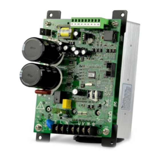
- Page 1 S100 Series Inverter Built-in type User Manual User Manual...
-
Page 2: Table Of Contents
Contents PREFACE ............................1 CHAPTER 1 DESCRIPTIONS FOR BODY AND INSTALLATION ............2 1.1. Model description ........................2 1.2 External dimensions ........................ 2 1.3 Product specification ........................ 3 CHAPTER 2 WIRING .......................... 4 2.1 Basic wiring diagram ........................ 4 2.2 Main circuit wiring ........................5 2.3 Precautions for wiring ...................... -
Page 3: Preface
● To check whether model number correspond with model and capacity your purchase order. ● To check whether there are damaged parts during transportation and delivering. If there are, do not connect with power supply. If any of the above checkpoints are not satisfactory, contact your SAVCH representative for a quick resolution. -
Page 4: Chapter 1 Descriptions For Body And Installation
1.1. Model description MODEL:S100-2S0.4G Model Input power supply Spec. SOURCE:AC 1PH 200~240V 50/60Hz Output power supply Spec. OUTPUT:3PH 0~240V 1.0KVA 2.5A Output frequency FREQUENCYRANGE:1.0~400Hz Designed by Taiwan Savch Electric SAVCH ELECTRIC CO.,LTD 100 - 2S SAVCH Product 220V 0.4:0.4kW G:constant series single phase 0.75:0.75kW... -
Page 5: Product Specification
1.3 Product specification Input voltage 220V Model number S100-2S 0.4G 0.75G Max applicable motor output power (kW) 0.75 Output rated capacity(kVA) Output rated current (A) Max output voltage(V) Three phase corresponding input voltage Output frequency range(Hz) 1.0~400Hz Rated Input current(A) Allowable variation range for Single phase power supply 200~240V 50/60Hz Voltage. -
Page 6: Chapter 2 Wiring
2.1 Basic wiring diagram Wiring of inverter can be divided into two parts, the main circuit and control circuit. Users must connect terminals as diagram shows. The following diagram is the standard wiring diagram of S100 series inverter. Main circuit power supply... -
Page 7: Main Circuit Wiring
2.2 Main circuit wiring Control circuit wiring diagram Wire gauge:12-20AWG Torque:5KG-CM Wiring Diagram... -
Page 8: Precautions For Wiring
2.3 Precautions for wiring •The selection of wire gauge during wiring shall be in accordance with relative specifications of Electrical code to guarantee the security. •A non-fuse switch and fuse must be connected between the single-phase AC input power supply and the main circuit terminals (L and N).A magnetic contactor(MC) is recommended to be connected in series additionally facilitating to switch off power supply simultaneously while the protection of inverter is in function. -
Page 9: Chapter 3 List Of Descriptions For Functional Parameters
CHAPTER 3 LIST OF DESCRIPTIONS FOR FUNCTIONAL PARAMETERS 0. User’s parameters set during running available Factory Parameter Parameter functions Setting range setting Inverter type code recognition 4:220V/0.4kW Factory 0-00 (Only for Reading) 5:220V/0.75kW setting Rated Current Display for 220V/0.4kW:2.5A Factory 0-01 Inverter (Only for Reading) - Page 10 1. Basic Parameters Set during running available Factory Parameter Parameter functions Setting range setting 1-09 Acceleration time 1 0.1 to 600s 10.0 1-10 Deceleration time 1 0.1 to 600s 10.0 1-11 Acceleration time 2 0.1 to 600s 10.0 ...
- Page 11 2. Operation mode parameters Set during running available Factory Parameter Parameter functions Setting range setting 0: Operated by keypad 1: Operated by external terminals. STOP on keypad available 2: Operated by external terminals. STOP on 2-03 Operation method keypad unavailable 3: Operated by Communications Interface RS485.
- Page 12 4. Input Function Parameters Set during running available Factory Parameter Parameter functions Setting range setting [VR] Input frequency bias 4-00 0.0 to 350Hz setting 0: Positive direction 4-01 Bias direction setting 1: Negative direction 4-02 Input frequency gain setting 1 to 200% ...
- Page 13 4. Input Function Parameters Set during running available Factory Parameter Parameter functions Setting range setting 0:Tracking downwards from speed before Speed tracking after external 4-09 external alarm alarm reset 1:Tracking upwards from min speed 5. Multi-step Speed and Auto-Program Operation Parameters ...
- Page 14 5. Multi-step Speed and Auto-Program Operation Parameters Set during running available Factory Parameter Parameter functions Setting range setting (Step 10 Time) 0 to 65500S 5-28 (Step 11 Time) 0 to 65500S 5-29 (Step 12 Time) 0 to 65500S 5-30 (Step 13 Time) 0 to 65500S 5-31...
- Page 15 7. Motor Parameters Set during running available Factory Parameter Parameter functions Setting range setting 7-00 Motor(Rated current) 30 to 120% 7-01 Motor(No load current) 0 to 90% Manual torque compensation 7-02 0.0 to 30.0% setting 7-03 Auto slip compensation setting 0.1 to 10 ...
- Page 16 Note: When setting the 8-00 parameter, it must be slowly increased from small until sufficient braking torque is obtained, but it should not exceed the rated motor. 9. Communications Parameters Set during running available Factory Parameter Parameter functions Setting range setting ...
-
Page 17: Chapter 4 Trouble Shooting
CHAPTER 4 TROUBLE SHOOTING Inverter is provided with functions of warning and protection such as over voltage, low voltage and over current. Once fault occurs, protection function shall act, inverter output stops, fault contactor act and also free running of motor shall stop. - Page 18 Display Descriptions of fault Corrective measures 1.Check motor load is not overlarge. Motor load overlarge 2.Check over-torque detection level setting (06-03). 1.Check screws securing inverter and motor are tightened. 2.Check insulation of wiring from U-V-W to motor. Over current during acceleration 3.Increase acceleration time.
- Page 19 ■ Innovate for more | win forever ■ Industry intelligence | Energy saving | Green power Savch wechat Service Number Quanzhou Factory Sales service contact address Address:3# Zixin Road, Jiangnan Hi-Tech Industrial Park, Quanzhou, Fujian, China Tel:0595-24678267 Fax:0595-24678203 Service Network Website:www.savch.net...


Need help?
Do you have a question about the S100 Series and is the answer not in the manual?
Questions and answers