
Related Manuals for Savch S3100A Series


Summary of Contents for Savch S3100A Series
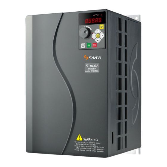
- Page 1 S3100A series inverter General Open-loop Vector Control (IM) User manual User Manual...
- Page 2 520031128082 Vision No. V1.2 Filing time 2021-08-17 SAVCH electric provide a full range of technical support for our customers. All users could contact with the nearest SAVCH office or service center, also could contact with our headquarters directly. SAVCH Electric reserves the copyrights and all rights,...
-
Page 3: Table Of Contents
CONTENTS PREFACE ................................. 1 1 SAFETY INSTRUCTIONS ......................... 2 1.1 Notes for Operation ..........................2 1.2 Notes for Operation Environment ....................4 2 HARDWARE DESCRIPTION AND INSTALLATION ................4 2.1 Operational Environment........................5 2.2 Model Description ..........................5 2.3 Inverter Specifications ........................7 2.4 Basic Wiring Diagram ........................ - Page 4 11 Fault and Protection Parameters ....................120 12 Serial Communication Parameters ..................... 127 13 Wobble Frequency Counting Parameters ................. 135 17 Torque Control Parameters ......................137 22 Control Optimization Parameters ....................138 99 Monitoring Parameters ........................140 6 TROUBLE SHOOTING .......................... 141 6.1 Failures &...
-
Page 5: Preface
Provided problems occur and solution is not provided in this instruction manual, contact your SAVCHELECTRIC representative or contact with our company directly. Our professional technicians will serve for you actively. And please continue to adopt products of SAVCH, give valuable opinion and advice. -
Page 6: Safety Instructions
1 SAFETY INSTRUCTIONS 1.1 Notes for Operation Before wiring △ ! CAUTION Specification of applying power supply shall correspond to input voltage of the inverter. DANGER Main circuit terminals must be correct, R/L1, S/L2 and T/L3 is input terminals and it’s forbidden to use mixing with U/T1, V/T2 and W/T3. - Page 7 △ ! CAUTION ● Never touch heat sink or discharging resistor since temperature may be very high. ● Since it is easy to change running speed from low to a high speed, verify safe working range of motor and machine before running. ●...
-
Page 8: Notes For Operation Environment
1.2 Notes for Operation Environment Direct sunlight Corrosive gas or fluids ? Salt Salt or saline Rain, moisture Iron chips and dust Below 10 degrees Celsius Force cool Force Force Force Force Force Extreme high ambient Large impelling Extreme low temperatures temperatures (Above 40℃) Electromagnetic waves Locations of inflammable... -
Page 9: Operational Environment
AIR EXCHANGE FAN INSIDE THE CABINET (CORRECT) (FALSE) (CORRECT) (FALSE) For cooling off, face shall be toward front and upper parts shall be upwards. Clearance shall meet the following specifications: SAVCH DIRECTION INSTALLATION 12cm 12cm 5 cm VENTILATION -10-+40℃ (b)SIDE (a)FRONT 2.2 Model Description... - Page 10 Model Input power supply Spec Output power supply Spec Output frequency 3100A - 4T 7.5G/11P Input power souece: Product 0.4: 0.4kW 90: 90kW SAVCH series 0.75:0.75kW 110:110kW 2T:3ph 220V 1.5: 1.5kW 132:132kW (Note: 2T2.2G or below 2.2: 2.2kW 160:160kW with compatibility of single phase) 4.0:...
-
Page 11: Inverter Specifications
2.3 Inverter Specifications 2.3.1 Standard Specifications 220V single phase/Three phase Series Item specification S3100A-2T□□□G 0.75 Maximum applicable motor 0.75 output power(kW) Maximum applicable motor output power(HP) Output rated capacity(kVA) 12.2 Output rated current(A) 17.0 Output frequency range 0~500Hz Overload capacity 150%-60s Max output voltage Same to input voltage... - Page 12 Three phase 440V Series Item Specification S3100A -4T□□□G/P 0.75 18.5 Maximum applicable 0.75 18.5 motor output power(kW) Maximum applicable 14.7 24.7 29.4 motor output power(HP) Output rated 19.1 24.4 28.2 34.3 capacity(kVA) Output rated current(A) (3.2) (4.7) (6.5) (11.8) (15) (21.7) (28.5) (35.4) (42) (60)
- Page 13 Item Specification S3100A-4T□□□G/P Maximum applicable motor output power(kW) Maximum applicable motor output power(HP) Output rated capacity(kVA) Output rated current(A) (426) (465) (520) (585) (650) (725) (820) (860) Output frequency range 0~500Hz G type:150%-60seconds Overload capacity P type:120%-60seconds Max output voltage same to input voltage Phase,voltage,Frequency Three phase·380-460V ·50/60Hz...
- Page 14 2.3.2 General specification Item Detailed information Control mode V/f control, open loop vector control, torque control range of output frequency 0~500.00Hz(V/f highest 3200.0Hz) Frequency setting 0.01 Hz resolution Output Frequency setting 0.01 Hz resolution PWM carrier frequency adjust from 0.5khz to 12khz Torque boost open loop vector control(SVC):G type:0.5Hz/150%,P type:0.5 Hz/120% Three types:line, multi-point.
- Page 15 Item Detailed information arrival, frequency limitation, torque limit Ready to run, AVI1>AVI2, upper limit frequency arrival, lower limit frequency arrival (operation related), undervoltage status output, communication setting, cumulative power-on time arrival, frequency arrival output, timing arrival output, offload, reverse In operation, the zero current state, the module temperature reaches, the output current exceeds the limit, the lower limit frequency arrives (the stop is also output), the alarm output (continues to run), and the running time arrives.
- Page 16 ● When there is an inductive load around the inverter, please ensure to install it. S3100A series Inverter: ●Input power terminals R / L1, S / L2, T / L3 are connected without any phase sequence.
- Page 17 Wiring shall be checked whether correct or not. Peripheral wiring shall fulfill the following requirements. (Warning:Do not use a buzzer of control circuit to check wiring) (A)Wiring for control circuit power supply must be isolated or far from other high voltage wirings or high current power lines, thus electromagnetic interference can be avoided.
- Page 18 ●Voltage drop of wiring shall be considered providing that inverter and motor are with an excessive distance. Voltage drop (V) = × wiring resistance (Ω/km) × wire length (m) × current × 10-3, load wave frequency shall be modified according to wiring prepared. Distance between inverter and motor wiring Below 50m Below 100m...
-
Page 19: Basic Wiring Diagram
Users must connect terminals as diagram shows. The following diagram is the standard wiring diagram of S3100A series AC motor driver. If only digital control panel was used, only main circuit terminal wiring applicable. - Page 20 Main Circuit Terminal Descriptions Description for S3100A Series inverter terminals Terminal symbols Function R/L1,S/L2,T/L3 Main circuit AC power supply input (For single phase input, connect R/L1 andT/L3) U/T1,V/T2,W/T3 Connect to motor P(+),DB Braking resistor connecting terminal P(+),N(-) Brake unit connection terminal...
-
Page 21: External Dimensions
2.5 External Dimensions 2.5.1 Inverter Size Model Fig. S3100A-2T0.4G S3100A-2T0.75G S3100A-2T1.5G 138.1 159.5 Size 1 S3100A-4T0.75G/1.5P S3100A-4T1.5G/2.2P S3100A-4T2.2G/4.0P S3100A-2T2.2G S3100A-2T4.0G S3100A-4T4.0G/5.5P 169.8 Size 2 S3100A-4T5.5G/7.5P S3100A-4T7.5G S3100A-2T5.5G S3100A-2T7.5G S3100A-4T7.5G/11P Size 3 S3100A-4T11G/15P S3100A-4T15G/18.5P S3100A-4T18.5G/22P S3100A-4T22G/30P 397.5 Size 4 S3100A-4T30G/37P S3100A-4T37G/45P S3100A-4T45G/55P S3100A-4T55G/75P Size 5... -
Page 22: Extemal Dimensions Of Inverter
2.5.2 Extemal Dimensions of Inverter Size 1 Unit: S3100A-2T0.4G~2T1.5G S3100A-4T0.75G/1.5P~4T2.2G/4.0P Size 2 Unit: S3100A-2T2.2G~2T4.0G S3100A-4T4.0G/5.5P~4T7.5G... - Page 23 Size 3 Unit: S3100A-2T5.5G~2T7.5G S3100A-4T7.5G/11P~4T18.5G/22P Size 4 Unit: S3100A-4T22G/30P~4T37G/45P...
- Page 24 Size 5 Unit: S3100A-4T45G/55P~4T110G Size 6 Unit: S3100A-4T110G/132P~4T160G/185P...
- Page 25 Size 7 Unit: S3100A-4T185G/200P~4T220G Size 8 Unit: S3100A-4T220G/250P~4T315G...
- Page 26 Size 9 Unit: S3100A-4T315G/355P~4T400G/450P Size 10 Unit: S3100A-4T450G/500P~4T500G...
-
Page 27: Multi-Functions Operation Keypad
2.5.3 Multi-Functions Operation Keypad ● Small power keypad (HCA-OP-A2) external dimensions and Installation dimensions Below 18.5kW (include 18.5kW) Unit:mm ● Large power keypad (HCA-OP-B2) external dimensions and Installation dimensions Above 22kW (include 22kW) Unit:mm Note:This keyboard can be extended with ordinary network cable (8 cores). - Page 28 Dimensions of epitaxial supporting box of extending keypad ● Below 18.5kW (include 18.5kW ) Unit:mm 58.5± 0.2 3.25 3.25 3.25 Cut-out size ● Above 22kW (include 22kW) Unit:mm 84.4 100.4 84.8± 0.3 131.6 147.6 Cut-out size...
-
Page 29: Keypad Description
3 KEYPAD DESCRIPTION 3.1 Keyboard Description for HCA-OP-A2 / HCA-OP-B2 Digital Operator Descriptions and functions of the keyboard Locating on AC motor drive, the digital operator has two spaces:display space and operating space. Programmed mode and different operation states shall be displayed on the display space, while for the operating space, it is an interface for communication of the operators and AC motor drive. - Page 30 Display and Keyboard Functions description Running key For start operation under operation keyboard mode To stop motor in running mode by pressing this key, limited by function code 08-02; Stop / reset key To reset fault in the state of fault alarm, free from function code 08-02.
-
Page 31: Description Of Keyboard Operation
3.2 Description of Keyboard Operation 3.2.1 Parameter Setting Here are three levels of menu: 1.Function code number group (first) 2.Function code labeling (second) 3.Function code value setting(third) Note:Press PRG / ESC or DATA / ENT to back to second-level menu when in the third-level. The difference between them is:DATA / ENT key stores the set parameter into control board before backing to second-level menu and shifts to the next function code automatically. -
Page 32: Failure Resetting
3.2.4 Password Setting S3100A series inverters provide user password protection function. When 08-00 is set to non-zero, it is the user password, exit the function code editing state, the password protection is effective, and press PRG / ESC key again to enter the function code editing state, "-----"... -
Page 33: Running State
" > "Key sequence switch to display the selected parameter, press DATA / ENT + QUICK / JOG key to switch to display the selected parameter to the left in order. 3.2.5.5 Alarms S3100A series inverter provides of alarm information. Please see the alarms and solutions of S3100A series inverter for details. -
Page 34: Quick Debugging
3.2.6 Quick Debugging Start Select control mode(set 01-00) Correctly set 01- 00=0? group 01 of motor parameters Select the suitable accel and decel time (set 00-07,00-08) Select running Motor parameters command channel self-taught (set 00-00) (set 01-01) Select the suitable frequency command (set 00-01,00-02 , etc) Select the start-stop... -
Page 35: Preliminary Operation-Not Connecting With Motor
3.3 Preliminary Operation-not Connecting With Motor • Prior to connecting power supply with AC motor drive, check and make sure that AC power supply voltage is within input voltage range of the drive. • Connect power supply to R/L1,S/L2 and T/L3 input terminals of the AC motor drive. •... - Page 36 □ Frequency command is controlled by keyboard. Three wire operation control mode Configuration 2 (04-00=1,04-01=3,04-02=2,04-09=3) STOP REV/FWD □ Frequency command is input by analog signals. (DC 0 to +10V)+(DC 4 to 20mA) Operation command is controlled by keyboard.(00-02 is set as 1,2) +10V 0-10V 4-20mA...
-
Page 37: Function Parameters List
4 FUNCTION PARAMETERS LIST 00 Basic functions parameters indicates that the parameters can be set during operation. Parame Factory Parameter function Setting range setting 0:Keyboard command (LED off) 1:Terminal command (LED on) 00-00 Command source selection 2:Communication command (LED flicker) 0:Stop memory and power failure storage Keyboard and terminal UP / DOWN ... - Page 38 00 Basic functions parameters indicates that the parameters can be set during operation. Parame Factory Parameter function Setting range setting Auxiliary frequency source Y range 00-16 0%~150% 100% when superimposed Single digit:Frequency source selection 0:Main frequency source X 1:Main and auxiliary calculation results (Operation relationship is determined by ten digits)
- Page 39 01 Motor control parameters indicates that the parameters can be set during operation. Parame Factory Parameter function Setting range setting 0:Speed sensorless vector control (SVC) 01-00 The first motor control mode 2:V/f control 0:No self-learning 1:Asynchronous motor static self-learning 01-01 Motor parameter self-learning 2:Asynchronous motor complete self-learning...
- Page 40 02 Vector control parameters indicates that the parameters can be set during operation. Parame Factory Parameter function Setting range setting 0:Parameter 02-07 setting 1:AVI1 2:AVI2 / ACI 3:reserved 4:PULSE pulse setting Torque upper limit source in 02-10 5: Communication setting speed control mode 6:MIN (AVI1, AVI2 / ACI) 7:MAX (AVI1, AVI2 / ACI)
- Page 41 03 V/f control parameters indicates that the parameters can be set during operation. Parame Factory Parameter function Setting range setting 03-08 Multi-point V/f voltage 3 0.0%~100.0% 0.0% 03-09 V/f slip compensation gain 0.0%~200.0% 0.0% 03-10 V/f overexcitation gain 0~200 ...
- Page 42 04 Input terminal parameters indicates that the parameters can be set during operation. Parame Factory Parameter function Setting range setting 0:No function 04-00 MI1 Terminal function selection 1:Forward running (FWD) 04-01 MI2 Terminal function selection 2:Reverse running (REV) 04-02 MI3 Terminal function selection 3:Three-wire control 04-03...
- Page 43 04 Input terminal parameters indicates that the parameters can be set during operation. Parame Factory Parameter function Setting range setting 46:Speed control / torque control switching 47:Emergency stop 48:External stop terminal 2 49:Deceleration DC braking 50:Clear the current running time 51-63:reserved ...
- Page 44 04 Input terminal parameters indicates that the parameters can be set during operation. Parame Factory Parameter function Setting range setting Single digit:AVI1 is below the minimum input setting selection 0:Corresponds to the minimum input setting AVI is less than the minimum ...
- Page 45 05 Multi-speed, simple PLC control indicates that the parameters can be set during operation. Parame Factory Parameter function Setting range setting 0:Stop at the end of a single run 1:Keep the final value at the end of a single Simple PLC operation mode ...
- Page 46 05 Multi-speed, simple PLC control indicates that the parameters can be set during operation. Parame Factory Parameter function Setting range setting Simple PLC stage 10 running 05-38 0.0s(h)~6500.0s(h) 0.0s(h) time Simple PLC step 10 acceleration 05-39 0~3 / deceleration time selection Simple PLC stage11 running...
- Page 47 06 Output terminal parameters indicates that the parameters can be set during operation. Parame Factory Parameter function Setting range setting 0:No output 06-00 MO1 output function selection 1:Inverter is running Control board relay function 06-01 2:Fault output (stop) selection (RA-RB-RC) 3:Frequency level detection FDT1 output 06-02...
- Page 48 06 Output terminal parameters indicates that the parameters can be set during operation. Parame Factory Parameter function Setting range setting 0:Pulse output (DFM (P)) DFM terminal output mode 06-05 selection 1:Switch output (DFM (M)) 0:Running frequency 1:Set frequency 2:Output current 3:Output torque 4:Output power...
- Page 49 07 Start and stop control parameters indicates that the parameters can be set during operation. Parame Factory Parameter function Setting range setting 0: Direct start 1: Rotation speed tracking restart Startup mode 07-00 2:Pre-excitation start 3:Reserved Startup frequency ...
- Page 50 08 Man-machine interface parameters indicates that the parameters can be set during operation. Parame Factory Parameter function Setting range setting 0: Only in the keyboard operation mode, the STOP/RESET key stop function is effective STOP/RESET key funciton 08-02 1: In any operation mode, the STOP/RESET key stop function is effective 0000~FFFF...
- Page 51 08 Man-machine interface parameters indicates that the parameters can be set during operation. Parame Factory Parameter function Setting range setting 0000~FFFF Bit00:Setting frequency(Hz) Bit01:BUS voltage(V) Bit02:MI input status Bit03:MO output status Bit04:AVI1 voltage(V) Bit05:AVI2/ACI voltage(V) 08-05 LED shutdown display parameters Bit06:Reserved Bit07:Count value Bit08:Length...
- Page 52 09 Accessibility parameters indicates that the parameters can be set during operation. Parame Factory Parameter function Setting range setting Acceleration time 2 09-03 0.0s~6500.0s Deceleration time 2 09-04 0.0s~6500.0s Acceleration time 3 09-05 0.0s~6500.0s Type setting Deceleration time 3 ...
- Page 53 09 Accessibility parameters indicates that the parameters can be set during operation. Parame Factory Parameter function Setting range setting Arbitrary arrival frequency 0.0%~100.0%( max frequency ) 09-31 0.0% detection width 1 Arbitrary arrival frequency 0.00Hz~ max frequency 09-32 50.00Hz detection value 2...
- Page 54 10 PID Control parameters indicates that the parameters can be set during operation. Parame Factory Parameter function Setting range setting 0:10-01 setting 1:AVI1 2:AVI2/ACI PID given source 3:Reserved 10-00 4:PULSE setting(MI5) 5: Communication setting 6: Multi-step speed command given PID data given ...
- Page 55 10 PID Control parameters indicates that the parameters can be set during operation. Parame Factory Parameter function Setting range setting PID initial value hold time 10-22 0.00~650.00s 0.00s Reserved 10-23 Reserved 10-24 0.0%:No judgment 10-25 PID feedback upper limit detection 0.0% 0.1%~100.0%...
- Page 56 11 Fault and protection parameters indicates that the parameters can be set during operation. Parame Factory Parameter function Setting range setting - 11-14 First failure type 0:No fault 1:Short circuit protection (sc) - 11-15 Second failure type 2:Overcurrent during acceleration (oc1) 3:Overcurrent during deceleration (oc2) 4:Overcurrent at constant speed (oc3) 5:Overvoltage during acceleration (ou1)
- Page 57 11 Fault and protection parameters indicates that the parameters can be set during operation. Parame Factory Parameter function Setting range setting Inverter status at the third (latest) - - 11-22 fault Power-on time at the third (latest) - - 11-23 fault Running time at the third (latest)
- Page 58 11 Fault and protection parameters indicates that the parameters can be set during operation. Parame Factory Parameter function Setting range setting Single digit:Reserved Tens digital:EEPROM read write fault 0:Coast to stop 1:Stop according to the stop mode Fault protection action selection 2 ...
- Page 59 11 Fault and protection parameters indicates that the parameters can be set during operation. Parame Factory Parameter function Setting range setting Judgment voltage of instantaneous 11-62 60%~100%(Standard bus Voltage) power failure 0:Invalid Lost load protection options 11-63 1:Valid Lost load detection level ...
- Page 60 13 Wobble frequency counting parameters indicates that the parameters can be set during operation. Parame Factory Parameter function Setting range setting 0:Relative to center frequency Wobble setting mode 13-00 1:Relative to Max frequency Wobble amplitude 13-01 0.0%~100.0% 0.0% Jump frequency amplitude ...
- Page 61 17 Torque control parameters indicates that the parameters can be set during operation. Parame Factory Parameter function Setting range setting Torque control reverse maximum 0.00Hz~ Max frequency 17-06 50.00Hz frequency Torque control acceleration time 17-07 0.00s~65000s 0.00s Torque control Deceleration time ...
- Page 62 99 Monitoring parameters indicates that the parameters can be set during operation. Parame Parameter function Setting range MI input status 99-07 MO output status 99-08 AVI1 voltage (V) 99-09 0.01V 99-10 AVI2/ACI voltage(V) 0.01V Reserved 99-11 Count value 99-12 Length 99-13 Load speed...
- Page 63 99 Monitoring parameters indicates that the parameters can be set during operation. Parame Parameter function Setting range 99-42 Visual display of MO input status MI function status visual display 99-43 1(function 01- function 40) MI function status visual display 99-44 2(function 41- function 50) 99-59...
-
Page 64: Description Of Functional Parameters
5 DESCRIPTION OF FUNCTIONAL PARAMETERS This chapter will give a detailed description of all functional parameters. It is divided into various parameter groups according to the attributes of the parameters; making parameter setting easier. In most applications, users can complete the settings before operation according to the related parameter settings in the parameter group. The parameter groups are as follows Parameter Function... - Page 65 00-01 Keyboard and terminal UP/DOWN setting selection Factory setting Stop memory and power failure storage Setting range Stop memory Stop no memory This function is only valid when the frequency source is set digitally. "Stop memory" refers to the inverter is stopped, a digital frequency keep the last set frequency retention time, keyboard ▲, ▼...
- Page 66 Among them, AVI1 is 0V ~ 10V voltage type input, AVI2/ACI can be 0V ~ 10V voltage input, can also be 4mA ~ 20mA current input, selected by the jumper on the control board. The corresponding relationship between the input voltage value of AVI1, AVI2/ACI and the target frequency can be freely selected by the user.
- Page 67 00-05 Lower limit frequency 0.00Hz Factory setting Setting range 0.00Hz~Upper limit frequency 00-04 When the frequency command is lower than the lower limit frequency set by 00-05, the inverter can be stopped, run at the lower limit frequency or run at zero speed, and set the operation mode through 09-14 (the set frequency is lower than the lower limit frequency operation mode).
- Page 68 Used to change the direction of the motor, its role is equivalent to changing the direction of motor rotation by adjusting any two motor lines. Note: After the parameters are initialized, the motor running direction will return to its original state. For occasions where it is strictly forbidden to change the direction of the motor after system debugging, please use it with caution.
- Page 69 Carrier frequency adjusts with temperature 00-12 Factory setting No automatic carrier reduction Setting range Automatic carrier reduction Low noise The carrier frequency is adjusted with the temperature. When the inverter detects that the radiator temperature is high, the carrier frequency is automatically reduced to prevent the inverter temperature from rising too high and reduce the overheating alarm.
- Page 70 00-16 Auxiliary frequency source Y range when superimposed Factory setting 100% Setting range 0%~150% When the frequency source is selected as "frequency superposition" (that is, 00-17 is set to 1, 3 or 4), these two parameters are used to determine the adjustment range of the auxiliary frequency source. 00-15 if you select 1 relative to the main frequency source X, the range of the auxiliary frequency source will change with the change of the main frequency X.
- Page 71 4: Switch between auxiliary frequency source Y and main and auxiliary calculation results When multi-function input terminal function 18 (frequency switching) is invalid, auxiliary frequency Y is used as the target frequency. When the multi-function input terminal function 18 (frequency switching) is valid, the main and auxiliary calculation results are used as the target frequency.
- Page 72 Acceleration and deceleration time unit Factory setting 00-22 Setting range 0.1s 0.01s S3100A has 3 kinds of acceleration and deceleration time unit selection. When modified, the decimal points of the 4 groups of acceleration and deceleration time will change, and the corresponding acceleration and deceleration time will also change.
-
Page 73: Motor Control Parameters
01 Motor Control Parameters 01-00 The first motor control mode Factory setting Speed sensorless vector control (SVC) Setting range Vf control 0: Speed sensorless vector control Refers to open-loop vector control, which is suitable for the usual high-performance control occasions. One inverter can only drive one motor. - Page 74 01-03 Motor rated frequency Factory setting Type setting Setting range 0.01Hz~ max frequency 01-04 Motor rated rotation speed Factory setting Type setting Setting range 1rpm~65535rpm 01-05 Motor rated voltage Factory setting Type setting Setting range 1V~2000V 01-06 Motor rated current Factory setting Type setting 0.01A~655.35A(Inverter power <=55kW)
-
Page 75: Vector Control Parameters
02 Vector Control Parameters 02 Group parameters are only valid for vector control, not for V/f control. 02-00 Speed loop proportional gain 1 Factory setting Setting range 1~100 02-01 Speed loop integration time 1 0.50s Factory setting Setting range 0.01s~10.00s 02-02 5.00Hz... - Page 76 02-06 Vector control slip gain 100% Factory setting Setting range 50%~200% For speed sensorless vector control, this parameter is used to adjust the speed stability accuracy of the motor: when the motor is loaded with a low speed, increase this parameter, and vice versa. 02-07 Digital setting of torque upper limit in speed control mode 150.0%...
-
Page 77: Control Parameters
02-13 Excitation adjustment proportional gain 2000 Factory setting Setting range 0~60000 02-14 Excitation adjustment integral gain 1300 Factory setting Setting range 0~60000 02-15 Torque adjustment proportional gain 2000 Factory setting Setting range 0~60000 02-16 Torque adjustment integral gain 1300 ... - Page 78 11: V/f half separation mode. In this mode, V and F are proportional, but the proportional relationship can be set by voltage source 03-13, and the relationship between V and F is also related to the rated voltage and rated frequency of motor group 01.
- Page 79 03-07 Multi-point V/f frequency point 3 0.00Hz Factory setting Setting range 03-05~motor rated frequency(01-03) 03-08 Multi-point V/f voltage point 3 0.0% Factory setting Setting range 0.0%~100.0% Parameters 03-03~03-08 can define multi-segment V/f curve. The curve of the multi-point V/f should be set according to the load characteristics of the motor. Note that the relationship between the three voltage points and the frequency point must meet: V1 <V2 <V3, F1 <F2 <F3.
- Page 80 03-11 V/f oscillation suppression gain Factory setting Type setting Setting range 0~100 The selection method of the gain is as small as possible under the premise of effectively suppressing the oscillation, so as to avoid adversely affecting the V/f operation. Select this gain to be 0 when there is no oscillation in the motor.
-
Page 81: Input Terminal Parameters
5.Multi-step speed command When the voltage source is a multi-speed command,set the 04 group and 05 group parameters to select the correspondence between the given signal and the given voltage. 6. Simple PLC When the voltage source is a simple PLC, you need to set 05 group of parameters to determine the given output voltage. - Page 82 Reserved 04-06 Factory setting Reserved 04-07 Factory setting These parameters are used to set the function of the digital multi-function input terminal Terminal. The functions that can be selected are shown in the following table: Setting Function Description value It is recommended to set the unused terminals to “no function” to No function prevent malfunction.
- Page 83 Setting Function Description value When the frequency is given as digital timing, this terminal can clear the frequency value changed by terminal UP/DOWN or UP/DOWN set to clear (terminal, keyboard UP/DOWN, so that the given frequency is restored to keyboard) the value set by 00-06.
- Page 84 Setting Function Description value When this terminal is valid, the PID integral adjustment function PID integration pause is suspended, but other PID adjustments are still effective. Frequency source X and When this terminal is valid, the frequency source X is replaced keyboard set frequency with the frequency given by the keyboard (00-06) switching...
- Page 85 Corresponding Command setting parameters Multi-step speed command 1 05-01 Multi-step speed command 2 05-02 Multi-step speed command 3 05-03 Multi-step speed command 4 05-04 Multi-step speed command 5 05-05 Multi-step speed command 6 05-06 Multi-step speed command 7 05-07 Multi-step speed command 8 05-08 Multi-step speed command 9 05-09...
- Page 86 04-09 Terminal command mode Factory setting Two-wire 1 Two-wire 2 Setting range Three-wire 1 Three-wire 2 Four-wire 1 This parameter defines four different ways to control the operation of the inverter through the external terminal Terminal. 0: Two-wire mode 1: This mode is the most commonly used two-wire mode. Terminal Reverse running is determined by TerminalMIx and MIy.
- Page 87 S3100A command MIx Forward RUN (FWD) Stop Stop MIy Reverse RUN (REV) Forward DCM Digital common Reverse Figure 5-7 Two-wire mode 2 2: Three-wire control mode1: This mode MIn is the enable terminal, the direction is controlled by MIx and MIy respectively.
- Page 88 When you need to run, you must first close the MIn terminal, the MIx pulse rising edge generates the motor running signal, and the MIy state generates the motor direction signal. When it is necessary to stop, it must be achieved by disconnecting the terminal signal of the MIn terminal. Among them, MIx, MIy, and MIn are the multi-function input terminals of MI1 to MI5, MIx is pulse effective, and MIy, MIn are level effective.
- Page 89 The following illustrations show two typical settings: Corresponding set value Corresponding set value (frequency, torque) (frequency, torque) 100.0% 100.0% 0V(0mA) 10V(20mA) 0V(0mA) 10V(20mA) -100.0% Figure 5-10 Correspondence relationship between analog input and set value AVI1 input filter time: adjust the sensitivity of analog input. Properly increasing this value can enhance the anti-interference of the analog quantity, but it will reduce the sensitivity of the analog input.
- Page 90 04-32 PULSE filter time 0.10s Factory setting Setting range 0.00s~10.00s This group of parameters is used for setting, the relationship between MI5 pulse frequency and the corresponding setting. The pulse frequency can only be input to the inverter through the MI5 channel. The application of this group of functions is similar to AVI curve 1, please refer to the description of AVI curve 1.
-
Page 91: Multi-Speed, Simple Plc Control
Setting range 0.0s~3600.0s It is used to set the delay time for the inverter to change the terminal state when the MI terminal changes. Currently, only MI1, MI2, and MI3 have the function of setting the delay time. MI terminal valid mode selection 1 04-38 Factory setting High level valid... - Page 92 05-13 Multi-step speed command 13 Factory setting 0.0% 05-14 Multi-step speed command 14 Factory setting 0.0% 05-15 Multi-step speed command 15 Factory setting 0.0% Setting range -100.0%~100.0% The multi-speed command can be used in three situations: as a frequency source, as a voltage source for V/f separation, as a set source for the process PID.
- Page 93 1: Keep the final value at the end of a single run: After the inverter completes a single cycle, it automatically maintains the running frequency and direction of the last segment. 2: Keep circulating: After the inverter completes one cycle, it automatically starts the next cycle until it stops when there is a stop command.
- Page 94 05-26 Simple PLC stage 4 running time Factory setting 0.0s(h) Setting range 0.0s(h)~6500.0s(h) 05-27 Simple PLC step 4 acceleration / deceleration time selection Factory setting Setting range 0~3 05-28 Simple PLC stage 5 running time Factory setting 0.0s(h) Setting range 0.0s(h)~6500.0s(h)
- Page 95 05-42 Simple PLC stage 12 running time Factory setting 0.0s(h) Setting range 0.0s(h)~6500.0s(h) 05-43 Simple PLC step 12 acceleration / deceleration time selection Factory setting Setting range 0~3 05-44 Simple PLC stage 13 running time Factory setting 0.0s(h) Setting range 0.0s(h)~6500.0s(h)
-
Page 96: Output Terminal Parameters
06 Output Terminal Parameters S3100A series inverters are equipped with a multi-function analog output terminal Terminal, a multi-function digital output terminal Terminal, a multi-function relay output terminal Terminal, a DFM terminal Terminal (can be used as high-speed pulse output terminal Terminal, also can be used as an open collector switch output). - Page 97 Setting Function Description value In the speed control mode of the frequency converter, when the output torque reaches the torque limit value, the frequency Torque limited converter is in the stall protection state and outputs an ON signal at the same time. When the power supply of the main circuit and the control circuit of the inverter has stabilized, and the inverter has not detected any Ready for run...
- Page 98 Setting Function Description value Lower limit frequency reached When the running frequency reaches the lower limit frequency, the (also output when stopped) ON signal is output. The signal is also ON in the stop state. When the inverter fails, and the fault handling mode is Continue to Warning output run, the inverter warning output.
- Page 99 Setting value Funtion Pulse or analog output 0.0%~100.0% corresponding function Count value 0 to maximum count value Communication setting 0.0%~100.0% 0~The rotation speed corresponding to maximum output Motor rotation speed frequency Output current 0.0A~1000.0A BUS voltage 0.0V~1000.0V 06-09 DFM (P) output maximum frequency Factory setting 50.00kHz Setting range...
-
Page 100: Start And Stop Control Parameters
06-22 MO output terminal valid state selection Factory setting Positive logic Negative logic Single digit Relay RA-RB-RC Tens digital Setting range Hundreds digital Reserved Thousands digital Reserved Ten thousands DFM(M) digital Define the output logic of output terminals MO1, relays RA-RB-RC and DFM(M). 0: positive logic, the digital output terminal and the corresponding common terminal are connected to the valid state, and disconnected to the invalid state;... - Page 101 Startup frequency 07-01 Factory setting 0.00Hz Setting range 0.00Hz~10.00Hz Startup frequency holding time 0.0s 07-02 Factory setting Setting range 0.0s~100.0s The inverter starts to run from the startup frequency (07-01), after the startup frequency holding time (07-02), then accelerates to the target frequency according to the set acceleration time. The startup frequency 07-01 is not limited by the lower limit frequency.
- Page 102 DC braking time at stop 0.0s 07-09 Factory setting Setting range 0.0s~ 100.0s Starting frequency of DC braking at stop: When the running frequency is reduced to this frequency during deceleration to stop, the DC braking process starts. Waiting time for DC braking at stop: After the running frequency is reduced to the initial frequency of DC braking at stop, the inverter will stop output for a period of time before starting the DC braking process.
- Page 103 The output frequency increases or decreases in a straight line. 4 kinds of acceleration/deceleration time can be selected through multi-function digital input terminals (04-00~04-04). 1: S curve acceleration and deceleration A The output frequency increases or decreases according to the S curve. The S curve is used in places that require gentle start or stop, such as elevators and conveyor belts.
-
Page 104: Man-Machine Interface Parameters
Output frequency Set frequency Rated frequency Time Figure 5-14 S curve acceleration and deceleration B Rotation speed tracking mode 07-14 Factory setting Start from stop frequency Setting range Start from zero speed Start from maximum frequency In order to complete the speed tracking process in the shortest time, choose the method of inverter tracking: 0: Track down from the frequency of power failure, this method is usually selected. - Page 105 08-01 QUICK/JOG key function selection Factory setting QUICK/JOG invalid Keyboard command channel and remote command channel (terminal Terminal command channel or communication command channel) switch Forward and reverse switching Setting range Forward jog Reverse jog Reserved QUICK/JOG is a multi-function key, and the function of QUICK/JOG key can be set through this parameter. You can use this key to switch between stop and running.
- Page 106 Bit11 Reserved Bit12 Count value Bit13 Length Bit14 Load speed Bit15 PID setting If the above parameters need to be displayed during operation, set the corresponding position to 1, set the binary number to hexadecimal and set it to 08-03. 08-04 ...
- Page 107 08-05 LED shutdown display parameters Factory setting 0000~FFFF Bit00 Setting frequency(Hz) Bit01 BUS voltage(V) Bit02 MI input status Bit03 MO output status Bit04 AVI1 voltage(V) Bit05 AVI2/ACI voltage(V) Bit06 Reserved Setting range Bit07 Count value Bit08 Length Bit09 PLC stage Bit10 Load speed Bit11...
-
Page 108: Accessibility Parameters
08-12 Load speed display the number of decimal places Factory setting Units: Number of decimal places for load speed Tens place:Number of decimal places for feedback speed 0 decimal place Setting range 1 decimal place 2 decimal places 3 decimal places Used to set the number of decimal places for load speed display.The following example illustrates the calculation method of load speed: If the load speed display coefficient 08-06 is 2.000, the load speed decimal point number 08-12 is 2 (2 decimal... - Page 109 09-04 Deceleration time 2 Factory setting Type setting 09-05 Acceleration time 3 Factory setting Type setting 09-06 Deceleration time 3 Factory setting Type setting 09-07 Acceleration time 4 Factory setting Type setting 09-08 Deceleration time 4 ...
- Page 110 Set the transition time at the output 0Hz during the inverter forward and reverse transition, as shown in Figure 5-16: Output frequency Forward rotation Reverse rotation Dead time Figure 5-16 Schematic diagram of forward and reverse dead time 09-13 Reverse control enable ...
- Page 111 09-17 Set cumulative running arrival time Factory setting Setting range 0h~65000h Used to set the running time of the inverter. When the accumulated running time (08-11) reaches this set running time, the inverter's multi-function output terminal Terminal (function 12) turns on. 09-18 ...
- Page 112 Output frequency Hz FDT hysteresis FDT Level =09-19x09-20 Time Frequency arrival detection signal MO1,RELAY,DFM(M) Time Figure 5-17 Schematic diagram of FDT level 09-21 Frequency reach detection width 0.0% Factory setting Setting range 0.00~100%(Max frequency ) When the running frequency of the inverter is within a certain range of the target frequency, the multi-function output terminal (function 4) of the inverter outputs an ON signal.
- Page 113 Whether the jump frequency is effective during 09-22 Factory setting acceleration and deceleration Invalid Setting range Valid When the setting is valid, when the operating frequency is within the range of the skip frequency, the actual operating frequency will skip the boundary of the set skip frequency. As shown in Figure 5-19. Output frequency Hz Jump frequency amplitude Jump frequency 2...
- Page 114 Output frequency Set frequency 09-25 09-26 Time Acceleration Deceleration time 2 time 2 Acceleration time 1 Deceleration time 1 Figure 5-20 Acceleration and deceleration time switching diagram 09-27 Terminal jogging priority Factory setting Invalid Setting range Valid This parameter can set the priority of the terminal jog command to the highest. When the terminal jog priority is effective, if the terminal jog command appears during the operation, the inverter will switch to the terminal jog running state.
- Page 115 When the output frequency is within the range of the positive and negative detection amplitude of any detected frequency, the multi-function output terminal (function 26/27) outputs an ON signal. S3100A provides two sets of arbitrary arrival frequency detection parameters, set frequency value and frequency detection range respectively.
- Page 116 09-37 Output overcurrent detection delay time 0.00s Factory setting Setting range 0.00s~600.00s When the output current of the inverter is greater than or exceeds the limit detection point and the duration exceeds the software overcurrent detection delay time, the inverter's multi-function output terminal (function 36) outputs an ON signal.
- Page 117 Output current Arbitrary arrival current width Arbitrary arrival current Arbitrary arrival current width Time Arbitrary arrival current detection signal MO1,RELAY,DFM(M) Figure 5-24 Schematic diagram of arbitrary arrival current detection 09-42 Timing function selection Factory setting Invalid Setting range Valid 09-43 Timed running time selection ...
- Page 118 09-47 Module temperature reached 75℃ Factory setting Setting range 0℃~100℃ When the temperature of the inverter radiator reaches this temperature, the multi-function output terminal (function 35) of the inverter outputs an ON signal. 09-48 Cooling fan control Factory setting Fans run during operation Setting range The fan keeps running...
-
Page 119: Pid Control Parameters
10 PID Control Parameters PID control is a common method of process control. By performing proportional, integral, and differential operations on the difference between the controlled variable feedback signal and the target signal, and by adjusting the output frequency of the inverter, a closed-loop system is formed to stabilize the controlled variable at Target value. - Page 120 AVI1+ AVI2/ACI MAX(|AVI1|,| AVI2/ACI |) MIN (|AVI1|,| AVI2/ACI |) This parameter is used to select the feedback signal channel of the process PID. The feedback value of the process PID is also a relative value, and the setting range is 0.0%~100.0%. PID action direction ...
- Page 121 Differential time Td1: Determines the strength of the PID regulator to adjust the deviation rate of change. The longer the differential time, the greater the adjustment intensity.Differential time refers to The feed rate changes by 100.0% within this time, and the adjustment amount of the differential regulator is the maximum frequency.
- Page 122 Reserved 10-14 Factory setting 20.0 Proportional gain Kp2 10-15 Factory setting Setting range 0.0~999.9 2.00s Integration time Ti2 10-16 Factory setting Setting range 0.01s~10.00s 0.000s Differential time Td2 10-17 Factory setting Setting range 0.000s~10.000s PID parameter switching conditions ...
- Page 123 PI parameter PI parameter 1 10-05、10-06、10-07 PI parameter 2 10-15、10-16、10-17 PID deviation 10-19 10-20 Figure 5-26 PID parameter switching 0.0% PID Initial value 10-21 Factory setting Setting range 0.0%~100.0% 0.00s PID initial value hold time 10-22 Factory setting Setting range 0.00s~650.00s When the inverter starts, the PID output is fixed at the initial PID value of 10-21, and the PID will start the...
-
Page 124: Fault And Protection Parameters
PID feedback lower limit detection 0.0% 10-26 Factory setting 0.0%: No judgment Setting range 0.1%~100.0% PID feedback loss detection time 0.0s 10-27 Factory setting Setting range 0.0s~20.0s This parameter can detect whether the PID feedback line is missing. When the PID feedback amount is less than the feedback loss detection value 10-26, and the duration exceeds the PID feedback loss detection time 10-27, the inverter alarms the fault PIDE, and handles it according to the selected fault handling method. - Page 125 When the cumulative output current of the inverter is greater than the product of the overload inverse time curve and 11-02, the inverter's multi-function output terminal (function 7) outputs the "motor overload pre-alarm" ON signal. Selection of short-circuit protection to ground ...
- Page 126 Output phase loss protection selection 11-13 Factory setting Units: output phase loss protection Tens place: output phase loss protection before running Setting range Disabled Enabled Choose whether to protect the output phase loss. First failure type 11-14 Factory setting Second failure type 11-15 Factory setting...
- Page 127 Inverter status at the second 11-32 fault Power-on time at the second 11-33 fault 11-34 Running time on second failure 11-37 Frequency at first failure 11-38 Current at first fault 11-39 Bus voltage at first fault The same to 11-17~11-24 Input terminal status at the first 11-40 fault...
- Page 128 Fault protection action selection 3 11-49 Factory setting Single digit Reserved Tens digital Reserved hundreds digital Power-on time arrival (EIND) (same as 11-47 digits) thousands Lost load(oLL) digital Coast to stop Setting range Stop according to the stop mode Decelerate to 7% of the rated frequency of the motor and continue to run.
- Page 129 11-59 Instantaneous power failure action selection Factory setting Invalid Setting range Deceleration Decelerate to stop Instantaneous power failure action pause judgment 11-60 Factory setting voltage Setting range 80~100% 11-61 0.5s Judgment time of instantaneous power failure voltage rise Factory setting Setting range 0.0s~100.0s...
- Page 130 Judgment time of instantaneous Bus Voltage power failure voltage rise 11-61 Judgment voltage of instantaneous power failure 11-62 Instantaneous power failure action pause judgment voltage 11-60 Running frequency 11-59=1 Deceleration Stop Stop Normal Deceleration Normal acceleration/ acceleration/ running time 4 running deceleration deceleration...
-
Page 131: Serial Communication Parameters
11-67 Reserved Factory setting 11-68 Reserved Factory setting 11-69 Reserved Factory setting 11-70 Reserved Factory setting 11-79 Reserved Factory setting 11-80 Reserved Factory setting 12 Serial Communication Parameters 12-00 Local address Factory setting Setting range 1~247,0 is broadcast address When the local address is set to 0, it is the broadcast address to realize the broadcast function of the host computer. - Page 132 It is used to determine the output unit of the current value when the communication reads the output current. Modbus protocol S3100A series inverters provide RS485 communication interface and support Modbus communication protocol. Users can realize centralized control through PC or PLC, set inverter running command, operating frequency, modify or read function code parameters, monitor inverter working status and fault information, etc.
- Page 133 Communication Frames Structure: The Modbus protocol communication data format of S3100A series inverters uses RTU mode, and new frames always start with a silent transmission time of at least 3.5 bytes. On a network that calculates the transmission rate in baud rate, the transmission time of 3.5 bytes can be easily grasped.
- Page 134 RTU Frame format: Frame header (START) 3.5 character time Slave address (ADR) Communication address:1~247 03: Read slave parameters; Command code (CMD) 06: Write slave parameters DATA(N-1) DATA(N-2) Data content: Function code parameter address, function code parameter number, function code …… parameter value, etc.
- Page 135 Command code: 06H Write a word (Word) For example: write 5000 (1388H) to the slave address 02H inverter 0003H address Host command information Slave response information Data address upper bit Data address upper bit Data address lower bit Data address lower bit Data content upper bit Data content upper bit Data content lower bit...
- Page 136 Definition of communication data address It is the definition of communication data address, which is used to control inverter operation, obtain the state information and relative function parameters. (1)Using method of function code parameter address Using numbers of function code as parameters to correspond to the register address, which has to be converted to hexadecimal system.
- Page 137 Function Address Description of data meaning description definition characteristic Analog AFM 2002H 0~7FFFmeans 0%~100% output control Pulse DFM (P) 2004H 0~7FFFmeans 0%~100% output control 3000H Running frequency 3001H Setting frequency 3002H Bus voltage 3003H Output voltage 3004H Output current 3005H Operation rotating speed 3006H Output power...
- Page 138 Description: Data read from 5000H compares with the actual fault as shown in the table below. Inverter fault DescriptionInverter fault information description addresss 0000:No fault 0015:EEPROM read write error 0001:Short-circuit protection 0016:Inverter hardware fault 5000H 0002:Acceleration over current 0017:Motor short circuit to ground 0003:Deceleration over current 0018:Reserved 0004:Constant speed over current...
-
Page 139: Wobble Frequency Counting Parameters
13 Wobble Frequency Counting Parameters The wobble frequency function is suitable for textile, chemical fiber and other industries, as well as occasions requiring traversing and winding functions.The wobble frequency function means that the output frequency of the inverter wobble up and down with the set frequency as the center. The trajectory of the running frequency on the time axis is shown in Figure 5-29. - Page 140 Sudden jump frequency amplitude: Sudden jump frequency = wobble amplitude AW × sudden jump frequency amplitude (13-02). If the wobble amplitude is selected relative to the center frequency (13-00=0), the kick frequency is the changing value. If the wobble amplitude is selected relative to the maximum frequency (13-00=1), the kick frequency is a fixed value.
-
Page 141: Torque Control Parameters
ON signal, and then the counter stops counting. When the count value reaches the designated count value 13-09, the multi-function output terminal (Function 9) outputs an ON signal. At this time, the counter continues to count until the "set count value" stops the counter. The designated count value 13-09 should not be greater than the set count value 13-08. -
Page 142: Control Optimization Parameters
Torque digital setting in torque control mode 17-03 Factory setting 150.0% Setting range -200.0%~200.0% Used to select the torque setting source. The torque setting adopts a relative value, and 100.0% corresponds to the rated torque of the inverter. Setting range-200.0%~200.0%, indicating that the maximum torque of the inverter is 2 times the rated torque of the inverter. - Page 143 In the 7-segment continuous modulation, the switching loss of the inverter is large, but the current ripple is small; in the 5-step intermittent debugging mode, the switching loss is small and the current ripple is large; but it may cause the motor at high frequency The instability of operation generally does not require modification. For the V/f operation instability, please refer to parameter 03-11, for inverter loss and temperature rise, please refer to parameter 00-10;...
-
Page 144: Monitoring Parameters
It is used to set the voltage value of the undervoltage fault UV of the inverter. 100.0% of the inverters with different voltage levels correspond to different voltage points, respectively: Single-phase 220V or three-phase 220V: DC200V Three-phase 380V: DC350V 99 Monitoring Parameters The 99 parameter group is used to monitor the running status information of the inverter. -
Page 145: Trouble Shooting
6 TROUBLE SHOOTING AC motor drive is provided with functions of warning and protection such as over voltage, low voltage and over current. Once fault occurs, protection function shall act, AC motor drive output stop, fault contactor act and also free running of motor shall stop. - Page 146 Display Description Possible reason corrective-measures 1. Install input reactor. 1. Abnormal changes in input voltage. Overvoltage at 2. Plus suitable energy constant speed 2. The load inertia is large. consumption brake components. 1. The input power supply voltage is low. 1.
- Page 147 Display Description Possible reason corrective-measures 1. Check the connector and 1. Poor contact of the control board reinsert the cable. connector. 2. Search for factory 2. The auxiliary power supply is maintenance. Current detection damaged. circuit fault 3. Search for factory 3.
-
Page 148: General Troubleshooting Method
6.2 General Troubleshooting Method Abnormal Check points Processing content phenomen Whether the power supply is input; Turn off the power first and then send it again; Has the power supply voltage been sent to R/L1, S/L2, and T/L3? Confirm the power voltage level; Whether the terminal screw is tight. -
Page 149: Maintenance And Ambient Elements
7 MAINTENANCE AND AMBIENT ELEMENTS For safety and normal operation, the inverter shall be provided with daily as well as periodical maintenance. Diagram below shows items that must be checked. Check shall only performed 10 minutes after charging LEDs of the inverter go off, to prevent injury to operators caused by residual power of inverter condenser. - Page 150 Inspection Corrective Inspection Assessment period Inspection content Inspection method measures to item base fault Daily Annual Check abnormal View inspection and Replace ○ vibration or noise auditory inspection cooling fan Cooling fan All OK Check no dust or ○ View inspection Remove chipping stacked Check no dust or...
-
Page 151: Braking Resistor Selection Guide
7.1 Braking Resistor Selection Guide The choice of braking resistor needs to be determined according to the power generated by the motor in the actual application system and has the relationship with the inertia of the system, the deceleration time, the energy that the bit can load, etc., and needs the customer to choose according to the actual situation. - Page 152 Braking Resistor List Applicable Full load Braking unit Braking motor Volt output Applied resistor Quantity torque resista torque specification 10%ED% Quantity (Nm) RXHG-80W-400R-J 150Ω 2.22 × (80W 400Ω) RXHG-80W-200R-J 80Ω 0.75 4.15 × (80W 200Ω) RXHG-300W-100R- 55Ω 8.31 × J(300W 100Ω) RXHG-300W-70R-J 35Ω...
- Page 153 Applicable Full load Braking unit Braking motor Volt output Applied resistor Quantity torque resista torque specification 10%ED% Quantity (Nm) DBU-4030D BRU-6KW-20R-J 304.65 20Ω (6000W 20Ω) 2(parallel connection) DBU-4045C BRU-9.6KW-13R6-J 415.43 13.6Ω (9600W 13.6Ω) 2(parallel connection) DBU-4045C BRU-9.6KW-13R6-J 498.51 13.6Ω (9600W 13.6Ω) 2(parallel connection) DBU-4110B PRU-30KW-6R8-J...
-
Page 154: Breaker,Cable And Contactor Specifications List
7.2 Breaker,Cable and Contactor Specifications List Input cable/Output cable Model Breaker(A) Contactor rated current A (Copper wire cable)mm S3100A-2T0.4G S3100A-2T0.75G S3100A-2T1.5G S3100A-2T2.2G S3100A-2T4.0G S3100A-2T5.5G S3100A-2T7.5G S3100A-4T0.75G/1.5P S3100A-4T1.5G/2.2P S3100A-4T2.2G/4.0P S3100A-4T4.0G/5.5P S3100A-4T5.5G/7.5P S3100A-4T7.5G S3100A-4T7.5G/11P S3100A-4T11G/15P S3100A-4T15G/18.5P S3100A-4T18.5G/22P S3100A-4T22G/30P S3100A-4T30G/37P S3100A-4T37G/45P S3100A-4T45G/55P S3100A-4T55G/75P S3100A-4T75G/90P S3100A-4T90G/110P S3100A-4T110G... -
Page 155: Input/Output Ac Reactor And Dc Reactor Specifications
7.3 Input/Output AC Reactor and DC Reactor Specifications Input AC reactor Output AC reactor Model (recommended) (recommended) reactor(recommended) × S3100A-2T0.4G ACL-0005-EISC-E2M8C OCL-0005-EISC-E1M4 × S3100A-2T0.75G ACL-0005-EISC-E2M8C OCL-0005-EISC-E1M4 × S3100A-2T1.5G ACL-0007-EISC-E2M0C OCL-0005-EISC-E1M4 × S3100A-2T2.2G ACL-0010-EISC-E1M4C OCL-0010-EISC-EM70 × S3100A-2T4.0G ACL-0020-EISC-EM70C OCL-0020-EISC-EM35 × S3100A-2T5.5G ACL-0030-EISCL-EM47C OCL-0030-EISCL-EM23C ×... -
Page 156: Input/Output Filter Specifications
7.4 Input/Output Filter Specifications Input filter specifications Output filter specifications Model (recommended) (recommended) S3100A-2T0.4G NF241B6/01 S3100A-2T0.75G NF241B6/01 The single phase filter is regardless of input and output S3100A-2T1.5G NF241B10/01 S3100A-2T2.2G NF241B10/01 S3100A-2T4.0G NFI-020 NFO-020 S3100A-2T5.5G NFI-036 NFO-036 S3100A-2T7.5G NFI-050 NFO-050 S3100A-4T0.75G/1.5P NFI-005 NFO-005... - Page 157 ■ Innovate for more | win forever ■ Industry intelligence | Energy saving | Green power Savch wechat Service Number Quanzhou Factory Sales service contact address Address:3# Zixin Road, Jiangnan Hi-Tech Industrial Park, Quanzhou, Fujian, China Tel:0595-24678267 Fax:0595-24678203 Service Network Service Hotline:4000-6161-619...
Need help?
Do you have a question about the S3100A Series and is the answer not in the manual?
Questions and answers