Advertisement
Quick Links
Advertisement

Related Manuals for Savch S3800 Series


Summary of Contents for Savch S3800 Series
- Page 1 S3800 Series Inverter High performance Close-loop Vector Control (IM) User manual User Manual...
- Page 2 520038131812 Vision No. V1.2 Filing time 2017-11-23 SAVCH electric provide a full range of technical support for our customers. All users could contact with the nearest SAVCH office or service center, also could contact with our headquarters directly. SAVCH Electric reserves the copyrights and all rights,...
- Page 3 CONTENTS PREFACE ............................1 1 Safety Instructions ........................2 2 Hardware Description and Installation ..................5 2.1 Operational Environment ....................... 5 2.2 Model Description ........................6 2.3 Inverter Specifications ......................7 2.4 Inverter Using and the Main Circurt wiring, the basic wiring diagram ........11 2.5 Operation Size ........................
- Page 4 8.3 Measurement of Electrical Amounts in Main Circuit ............284 8.4 Insulation Test ........................285 9 Options ............................ 286 9.1 Braking Resistor List ......................286 9.2 Input/Output AC/DC Reactor Specifications List for S3800 Series Inverter ......287 9.3 Optional Card ........................287...
- Page 5 ●To check whether model number correspond with model and capacity your purchase order. ●To check whether there are damaged parts during transportation and delivering. If there are, do not connect with power supply. If any of the above checkpoints are not satisfactory, contact your SAVCH ELECTRIC representative for a quick resolution.
- Page 6 1 Safety Instructions 1.1 Notes for Operation Before wiring △ ! CAUTION Specification of applying power supply shall correspond to input voltage of the inverter. DANGER Main circuit terminals must be correct, R/L1, S/L2 and T/L3 is input terminals and it’s forbidden to use mixing with U/T1, V/T2 and W/T3.
- Page 7 △ ! CAUTION Never touch heat sink or discharging resistor since temperature may be very high. Pay attention to relative settings before using the brake. Do not check signals during running. Turn off the power and check that the charging resistance lamp "CHARGE" goes out before reassembling or checking.
- Page 8 1.2 Notes for Operation Environment Direct sunlight Corrosive gas or fluids ? Salt Salt or saline Rain, moisture Iron chips and dust Below 10 degrees Celsius Force cool Force Force Force Force Force Extreme high ambient Large impelling Extreme low temperatures temperatures (Above 40℃) Electromagnetic waves Locations of inflammable...
- Page 9 For cooling off, face shall be toward front and upper parts shall be upwards. Clearance shall meet the following specifications:(If the inverter is installed inside the cabinet or environment is allowable, dust cover shall be available to be removed for ventilating.) SAVCH DIRECTION INSTALLATION...
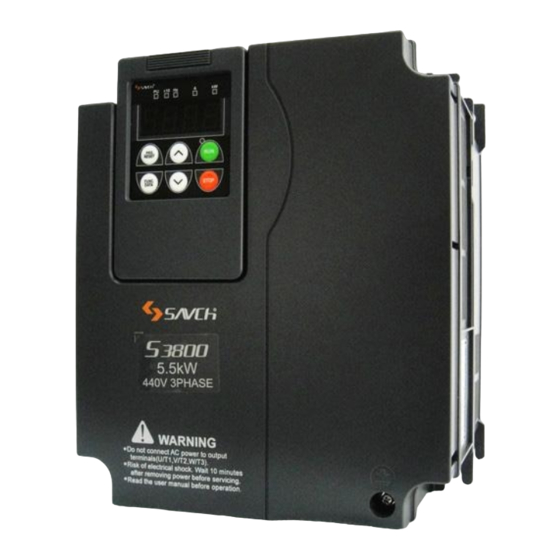
- Page 10 SOURCE: AC 3PH 380~480V 50/60Hz Input power supply Spec OUTPUT: 3PH 0~480V 2.8kVA 4A Output power supply Spec FREQUENCY RANGE: 0.1~500Hz Output frequency S/N: NJ3019380000037 Designed by Savch Electric SAVCH ELECTRIC CO.,LTD 3800 - 4T Product series Input power SAVCH Applicable...
- Page 11 2.3 Inverter Specifications 2.3.1 Standard specifications (1.5 to 110kW) HD (Heavy Duty) spec for heavy duty Item Specifications Type(S3800-4T***G) 18.5 Nominal applied motor[kW] (rated 18.5 output) Rated power [kVA] (*2) Voltage [V] 3 ph 380~480V(With AVR function) Rated output Rated current [A] 13.5 18.5 24.5...
- Page 12 (5.5 to 110kW) ND (Normal Duty) spec for light duty Item Specifications Type(S3800-4T***G) 18.5 30 37 Nominal applied 18.5 37 45 90 110 132 motor[kW] ( *1) (rated output) Rated power [kVA] (*2) 57 69 114 134 160 192 Voltage [V] 3 ph 380~480V(With AVR function) Rated output...
-
Page 13: Control
Item Explanation Speed Under V/F control · 1 :100 (Minimum speed:Base speed, 4P, 7.5 to 1500 r/min) control of with speed · 1 :2 (Constant torque range:Constant output range) range sensor Under Speed Dynamic torque · Analog setting:±0.2% of maximum speed (at 25 ±10℃) control vector control with ·... - Page 14 Item Explanation · Analog input adjustment (gain/offset/filter time constant), frequency limiter (high and low), bias frequency, jump frequency, jogging operation, pre-excitation, switch to commercial power, commercial power switching sequence,cooling fan ON/OFF control, select motor 2 to 4, protect motor from dew condensation, universal DI, universal DO,universal AO, rotational direction limitation.
- Page 15 2.4 Inverter Using and the Main Circurt wiring, the basic wiring diagram 2.4.1 Peripheral equipment application and precautions Power: ●Use the power supply in the permissible specifications of the inverter model to avoid damaging the drive. Power supply No fuse circuit breaker(MCCB): ●...
- Page 16 Wiring shall be checked whether correct or not. Peripheral wiring shall fulfill the following requirements. (Warning:Do not use a buzzer of control circuit to check wiring) (A)Wiring for control circuit Power supply must be isolated or far from other high voltage wirings or high current power lines, thus electromagnetic interference can be avoided.
- Page 17 ●Voltage drop of wiring shall be considered providing that inverter and motor are with an excessive distance.Voltage drop (V) = × wiring resistance (Ω/km) × wire length (m) × current × 10 , load wave frequency shall be modified according to wiring prepared. Distance between inverter and motor wiring Below 50M Below 100M...
- Page 18 2.4.2 The selection of peripheral devices Moulded Case Circuit Breaker (MCCB) / Earth Leakage Circuit Breaker (ELCB) Rated Current (A) of MCCB, ELCB Supply Applicable standard Type of inverter Specification DC reactor voltage motor(kW) S3800-4T1.5G S3800-4T2.2G S3800-4T4.0G S3800-4T5.5G S3800-4T7.5G S3800-4T11G S3800-4T15G 18.5 S3800-4T18.5G...
- Page 19 Recommended Screw Speciation Screw Speciation Control power auxiliary Supply Main circuit Grounding Type of inverter Reference input [R1, T1] voltage Screw Torque Screw Torque Torque Screw Size Size (N· m) Size (N· m) (N· m) S3800-4T1.5G Fig ure A S3800-4T2.2G S3800-4T4.0G S3800-4T5.5G Fig ure B...
- Page 20 Figure C Figure D Figure E Figure F...
- Page 21 Recommended wire specification Recommended wire specification (mm Main circuit Suppl Applicable Speci Braking output Type of Ground Inverter DC reactor standard ficati resistor [L1/R,L2/S,L3/T] voltag inverter terminal output[ connection motor(kW) connection DC reactor U,V,W] [P1,P(+)] [P(+),DB] S3800-4T1.5G S3800-4T2.2G S3800-4T4.0G S3800-4T5.5G S3800-4T7.5G S3800-4T11G S3800-4T15G...
- Page 22 2.4.3 Wiring of main circuit terminal and grounding terminal Wiring dianram...
- Page 23 (Note 1) When retaining the alarm signal (for any fault) or the keypad for display after the main power of inverter is disconnected, connect the terminals R1 and T1 to the power supply. The inverter can still run if the power supply is not input to the terminals.
- Page 24 (4) Connect the brake resistor terminals P(+),DB (below a capacity of 22kW) Braking Built-in braking Power (kW) Connecting accessories Steps transistor resistor 1.5~3.7 Built-in Built-in Braking resistor (power rises) 1),2),3) 5.5~22 Built-in Not installed Braking resistor 2),3) Use the braking resistor with greater capacity to improve the braking power when the power of built-in braking resistor below a capacity of 5.5kW is insufficient (high frequency running or high inertia load running, etc.).
- Page 25 2.4.4 The function description of the control terminal Functions of control terminals are listed in the following table. Control terminal connection methods are different due to different function parameter settings in line with use purpose of the inverter. Perform wiring properly to reduce the noise caused by the main circuit wiring. Function of Control Terminals Categor Terminal...
- Page 26 Categor Terminal Terminal Functions symbol name (1) PTC / NTC thermistor used to protect the motor can be connected. Switch SW5 (refer to 2.4.5) on the board to the PTC / NTC side. The internal circuitry of switching SW5 (switch of terminal AUI) to the PTC / NTC side is shown in the right figure.
- Page 27 Cate Terminal Functions Terminal name gory symbol Digital input 1 (1) Set various signals towards function parameters 01.01~01.09,01.98,01.99. Digital input 2 (2) Apply SW1 input modes:drain / source switching. Digital input 3 (3) Switch from [short circuit ON] to [short-circuit OFF] of the operation Digital input 4 mode between each digital input terminals and terminals DCM.
- Page 28 Cate Terminal Functions Terminal name gory symbol <Programmable <Control circuit> controller> SINK Optocoupler SOURCE MI1~MI9, FWD,REV (a)Switch at the drain side <Programmable <Control circuit> controller> SINK Optocoupler SOURCE MI1~MI9, FWD,REV (b)Switch at the source side Programmable controller circuit ■ Precautions of terminal MI7 pulse input Terminal MI7 cannot correctly identify the input pulse due to the wiring’s stray capacitance when being connected to the pulse generator of open collector output.
- Page 29 Cate Terminal Functions Terminal name gory symbol Output pulse signal. Content of the signal can be chosen from the same function as the AFM through the setting of function parameters 00.35. * Impedance can be connected:Min 5kΩ (Up to two analog voltmeter (DC0~10V can be connected, the input impedance is 10kΩ).
- Page 30 Categ Terminal Functions Terminal name symbol Tip ◆Connect the programmable controller to terminals MO1 ~ MO4 Circuits of transistor outputs of connecting the inverter on programmable controller are as shown in Figure. <Programmable <Control circuit> <Programmable <Control circuit> controller> controller> Optocoupler Optocoupler (b) Diagram of connection with the source input...
- Page 31 2.4.5 Control panel switch function description △ ! Danger Before proceeding to the transfer of various switches, turn OFF the power and wait at least five minutes for inverters of 22kW or below, or at least ten minutes for inverters of 30kW or above. Make sure that the LED monitor and charging lamp are turned OFF.
- Page 32 The locations of various switches on control circuit board are shown as follows. The locations of various switches on control circuit board 2.4.6 Installation and connection of the keypad Keypad can be installed in the disc for operation. Install keypad in the disc...
- Page 33 Keypad can be installed in the disc with following accessories. Accessory Name Type Notes (Note 1) Extension cable 3m,2m,1m There are three kinds of length of the extension cable (3m,2m,1m)。 M3 ×□ ( Note 2) Installing screw 2 (Supplied by users) (Note 1) Use network cable sold on the market.
- Page 34 2.6 Inverter Size 2.6.1 External dimensions Unit:mm External Dimensions(mm) Inverter type Figure S3800-4T1.5G 2*Ф6 S3800-4T2.2G 150.5 117.5 S3800-4T4.0G S3800-4T5.5G S3800-4T7.5G S3800-4T11G 2*Ф10 195.7 99.5 96.5 S3800-4T15G S3800-4T18.5G S3800-4T22G 2*Ф6.5 S3800-4T30G 454.5 S3800-4T30G S3800-4T37G 3*Ф10.5 10.5 S3800-4T45G S3800-4T55G S3800-4T75G 3*Ф12.5 S3800-4T90G 12.5 S3800-4T110G 2.6.2 Inverter main body figure...
- Page 35 Figure C(S3800-4T15G~4T22G) Figure D(S3800-4T30G-B on the way) Figure E(S3800-4T30G~4T55G) Figure F(S3800-4T75G~4T110G)
- Page 36 3 Keypad Description 3.1 Overview of Keypad Functions The keypad could be divided into two parts, i.e. display area and key control area. Display area displays parameter settings and indicates different operation status. Key control area is convenient for the user to take operation for the inverter.
- Page 37 Operation using the Keypad Operation Modes Selection Tips:Double key operation means:operation by pressing 2 keys simultaneously and the sign is “+”. Menu switching under programming mode Functional parameter setting or modification Tips:Cursor moving:When functional parameter data is changed, press key for more than 1s continuously. It enables move the flashing position and the data on the position could be changed.
- Page 38 3.2 Overview of Operation Modes The S3800 features the following three operation modes Table 3.2 Operation Modes Operation Description Mode It is the mode enters into automatically after power on. It could take frequency setting, PID setting, specify run/stop commands in regular operation. Running Mode It could monitor the running status in real time.
- Page 39 01.43 Exam Monitored Items LED Display Unit Description of Display Value Function parameter □Hz ■A □kW Output current 13.50 Current output from the inverter in RMS □Hz □A □kW Output voltage 380U Voltage output from the inverter in RMS □Hz □A □kW Output torque Calculated output torque □Hz □A ■kW...
- Page 40 ■ Check a light alarm If a light alarm appears, it displays L-AL on the LED monitor. If the light alarm would be required to check, enter programming mode by pressing key and check on “Maintenance Information” E_36. Additionally, to check the past light alarm, it’s also possible to check on E_37 (light alarm (previous)) ~E_39(light alarm (previous 3)) simultaneously.
- Page 41 LED Display Menu Main Functions on keypad I/O Checking d.i_o Displays external interface information. Maintenance E.C_S Displays maintenance information including cumulative run time. Information Alarm Displays the recent four alarm codes. Also this menu is used to view F.A_L Information the information on the running status at the time the alarm occurred.
- Page 42 Keypad Item Unit Description Display The PID feedback amount is displayed after conversion to the virtual physical values (e.g., temperature or pressure) of the object to be controlled using function parameter 01.40 and 01.41 data PID Feedback C_11 None (PID display coefficients A and B). amount Display value = (PID feedback amount) ×(Coefficient A - B) + B When PID control is set as no action, it displays “----”.
- Page 43 Keypad Item Unit Description Display Current position C_27 Pulse Current position pulse for positioning control (server locking) pulse, 4-multiplied Position deviation C_28 Pulse Position deviation pulse for positioning control (server locking). pulse, 4-multiplied ■ Run Status (C_07 ) and Display Method of Run Status 2(C_23 ) To display the run status /run status 2 in 4-bit in hexadecimal, as in Table 3.6 and Table 3.7, it distributes the run status into 0-15 bits.
- Page 44 Table 3.8 Display Example of Run Status LED No. LED4 LED3 LED2 LED1 mBUSY mALM mDEC mACC mNUV mBRK mINT mEXT mREV mFWD Mark Binary System Displ LED4 LED3 LED2 LED1 keypad In mple hexadeci ■ Hexadecimal conversion table Use binary system 4 bit unit to be converted into hexadecimal. The conversion table is as the following. Table 3.9 Conversion of Binary and Hexadecimal Binary Hexadecimal...
- Page 45 Keypad Item Description Display ― d_10 Reserved Terminal MI7 Pulse Input d_11 Display pulse count of input terminal MI7 pulse train signal. Monitor PG Detection Pulse rate Pulse rate of the A/B phase signal feedback from the reference d_15 (Instruction Side AB Phase) PG (1000p/s is displayed as 1.00.) PG Detection Pulse rate Pulse rate (p/s) of the Z phase signal feedback from the...
- Page 46 ● Display in Hexadecimal Distribute all I/O terminals as 16-bit binary system from 0 bit to 15-bit. It is viewed as “0” when there is no distribution. Distributed data is displayed as 4-bit hexadecimal number system number in keypad (0 ~ F). Digital input terminals FWD and REV are distributed to bit 0 and bit 1.
- Page 47 3.4.4 Reading maintenance Information Menu code E” Maintenance Information:E.C_S” of program mode displays necessary information in inverter maintenance. Table 3.13 maintenance Information items Keypad Item Display Contents Display Displays the content of the accumulative power-on time counter of the inverter. Measurement Range:0~65,535 h Display:Divided the accumulative run time into interactive display of front 2 bits and back 3 bits.
- Page 48 Keypad Item Display Contents Display Cumulative power data means the data of Input watt hour(kWh)×functional parameter 01.51. The setting range of functional parameter 01.51 is 0.000~9999. Displays Unit:None E_10 Cumulative power data (Display:0.001 ~9999. it will be reset to”0” when it is more than 9999.
- Page 49 Keypad Item Display Contents Display Number of startups for Displays cumulative starting times of the 2 motor. Display method is the E_32 the 2 motor same with E_08 Number of startups for Displays cumulative starting times of the 3 motor. Display method is the E_33 the 3 motor...
- Page 50 Keypad Display Content Description Display Displays the cumulative time of power-ON time counter of the inverter. Measurement Range:0~65,535 h Display:Divided the accumulative run time into interactive display of front 2 bits and back 3 bits. E.g. 0 ⇔ 535h (535 h) F_07 Cumulative running time 65 ⇔...
- Page 51 3.5 Alarm Mode When an alarm appears, then is the inverter switches to alarm mode automatically, and it displays the alarm code in the keypad. ■Resetting alarm After the alarm cause is removed and key is pressed, the alarm condition will be reset, and the inverter will go back to the Running mode ■Displays alarm history In addition to the current (latest) alarm, we can view past 3 alarms and multiple alarms,.
- Page 52 4 Running 4.1 Test Run 4.1.1 Confirmation before power-ON Before power- ON, check the following items. (1) Check that the wiring is correct. Especially check the wiring to the inverter input terminals L1/R, L2/S and L3/T and output terminals U, V, and W. Also check that the grounding wires are connected to the grounding terminals (G) correctly.
- Page 53 Function Name HD mode ND mode Notes parameter When 00.80 is changed, Current 00.44 Initial value 160% Initial value 130% it is initialized to the value limiter level specifized at left. Under ND mode when the Setting range Setting range max.
- Page 54 Furthermore, through functional parameter 04.68, it can set valid/invalid slip compensation according to all status of motor. Motor driving conditions Motor driving Frequency range 04.68 Data Accel./Decel. Constant speed Base frequency or below Above the base frequency Valid Valid Valid Valid Invalid Valid...
- Page 55 Note:Since slip compensation, dynamic torque vector control, and vector control with/without speed sensor use motor parameters, the following conditions should be satisfied; otherwise, full control performance may not be obtained.. ·1 control motor ·Motor parameters 03.02, 03.03, 03.06~03, 23, 03.55 and 03.56 should be properly configured or auto- tuning should be performed.
- Page 56 03.04 Auto-Tuning Select under the Motor parameters subjected to tuning Tuning Action type following conditions Data Primary resistance %R1 (03.07*) Leakage reactance %X (03.08*) Tune while Tuning with the motor Cannot rotate the the motor Rated Slip (03.12*) stopped motor. stops % X correction factor 1 (03.53, 03.54)
- Page 57 Note: Do not execute motor tuning with output filter unless the filter is a reactor type only. A tuning error may result if any other type filter is in use.please set the primary resistance% R1, leakage reactance% X, no- load current, and rated slip frequency of the inverter in function parameters before replacement. Vibration that may occur when the motor's coupling is elastic can be regarded as normal vibration due to the output voltage pattern applied in tuning.
- Page 58 All types of control methods are displayed in “V/f:V/f control”, “No PG:vector control without sensor”, and “PG:vector control with sensor”. Selection Control Method Auto- 03.04* Motor parameters Condition of Tuning Tuning Action without subjected to tuning Auto-tuning Data type type Primary resistance %R1 (03.07*) Tune...
- Page 59 ⑥ The motor is again accelerated to approximately 50% of the base frequency and then tuning starts. Upon completion of measurements, the motor decelerates to a stop. (Estimated tuning time: acceleration time +20~160 + deceleration time) ⑦ After the motor decelerates to a stop, tuning continues with the motor stopped. (Tuning time:max. 20~30s.) ⑧...
- Page 60 4.1.6 The basic function parameters of V/f control with speed sensor/ dynamic torque vector control with speed sensor to set and auto-tuning. <3> Under V/f control with speed sensor 00.42* = 3) or dynamic torque vector control with speed sensor (00.42* = 4), any of the following cases requires configuring the basic function parameters given below and auto-tuning.
- Page 61 (3) Auto-tuning execution procedures ① Set “1” or “2”in function parameter 03.04 and press key. ② Enter a run command. (press key on keypad as forward running. If it takes reverse running, change the data of function parameter 00.02). ③ After enter a run command, Tuning starts with the motor stopped . Auto-tuning time:max. 40 to 80 s. ④...
- Page 62 Control Method Function Name Regulation Points without parameter Motor 1 Slip For excessive slip compensation during braking, ○ ○ 03.11 * compensation decrease the gain; for insufficient one, increase the × × gain for braking gain. Output current fluctuation If the motor vibrates due to current fluctuation, ○...
- Page 63 4.2 Special Operations 4.2.1 Jogging (inching) the motor It shall take the following procedure for jogging (1) Enter into jogging status. (Displays JoG in keypad) · Switch the inverter to Running mode. · Press the “ key + key” simultaneously. After displaying jogging frequency for 1 s in the keypad, it returns to display JoG.
- Page 64 5 Function Parameters List 5.1 Function Parameters List Users can set the function parameter values to control and apply various functions of S3800 series inverter. Before starting to narrate this chapter, first describe function parameter format as follows: Function parameter...
- Page 65 ■The relationship between function parameters and control modes S3800 series inverter can help users achieve the following drive controls. Depending on different control modes, the effective range of individual function parameter is different as well. The range of each function parameter classified according to different control modes is shown in the "control mode"...
- Page 66 00:Basic functions parameters Control Method Param Factory Parameter Functions Setting Range Without Torque eter Default control 0:keypad command mode (Now the running direction is set by external terminal) Operation command ○ ○ ○ ○ ○ 00.02 source selection 1:External terminal command mode 2:keypad forward command mode 3:keypad reverse command mode Maximum output...
- Page 67 00:Basic functions parameters Control Method Param Factory Parameter Functions Setting Range Without Torque eter Default control ○ ○ ○ ○ 00.23 Starting frequency 1 0.0~60.0Hz × Starting frequency 1 ○ ○ ○ ○ 00.24 0.00~10.00s 0.00 × holding time ○...
- Page 68 00:Basic functions parameters Control Method Param Factory Parameter Functions Setting Range Without Torque eter Default control 4:Output torque 5:Load factor 6:Input power 7:PID feedback amount 8:PG feedback amount 9:DC link bus voltage 10:Universal AO 13:Motor output power 14:Analog output calibration (+) 15:PID command value (SV) 16:PID output value (MV) 17:Positional deviation in synchronous...
- Page 69 00:Basic functions parameters Control Method Param Factory Parameter Functions Setting Range Without Torque eter Default control Electronic Thermal Overload Allowable ○ ○ ○ ○ ○ 00.51 average loss 0.001~99.99kW 0.001 (protection for braking resistor) Electronic Thermal Overload braking 0.01~999Ω ○...
- Page 70 01:External terminal function parameters Control Method Parame Factory Parameter Functions Setting Range Without Torque default control 19(1019) :Enable data change with ○ ○ ○ ○ ○ keypad ( data can be changed ) [mWE-KP] ○ ○ ○ ○ 20(1020):Cancel PID control [mHz/PID] ×...
- Page 71 01:External terminal function parameters Control Method Parame Factory Parameter Functions Setting Range Without Torque default control 75(1075):Count the run time of ○ ○ ○ (commercial power-driven) motor 4 × × [mCRUN-M4] ○ ○ ○ ○ 76(1076):Droop control [mDROOP] × ○ ○...
- Page 72 01:External terminal function parameters Control Method Parame Factory Parameter Functions Setting Range Without Torque default control 17(1017):Simple PLC operation cycle ○ ○ ○ ○ completion [mTO] 18(1018):Simple PLC sections instruction ○ ○ ○ ○ No.1 [mSTG1] 19(1019):Simple PLC sections instruction ○...
- Page 73 01:External terminal function parameters Control Method Parame Factory Parameter Functions Setting Range Without Torque default control 58(1058):Frequency ( speed ) detection 3 ○ ○ ○ ○ ○ [mFDT3] 59(1059):ACI terminal wire break ○ ○ ○ ○ ○ detected [mACIOFF] ○ ○...
- Page 74 01:External terminal function parameters Control Method Parame Factory Parameter Functions Setting Range Without Torque default control PID display –999~0.00~9990 ○ ○ ○ ○ 01.40 × coefficient A PID display –999~0.00~9990 ○ ○ ○ ○ 01.41 0.00 × coefficient B Display filter time ○...
- Page 75 01:External terminal function parameters Control Method Parame Factory Parameter Functions Setting Range Without Torque default control 0:Auto-saving ( when the main power is Saving of digital ○ ○ ○ ○ ○ turned off ) 01.64 reference frequency 1:Press the FUNC/DATA key to save Reference loss 0:Decelerate to stop, 20 to 120% , ○...
- Page 76 01:External terminal function parameters Control Method Parame Factory Parameter Functions Setting Range Without Torque default control ○ ○ ○ ○ 20(1020):Cancel PID control [mHz/PID] × 21(1021):Switch Forward & reverse ○ ○ ○ ○ × [mIVS] ○ ○ ○ ○ ○ 22(1022):Interlock [mIL] 23(1023):Cancel Torque control...
- Page 77 01:External terminal function parameters Control Method Parame Factory Parameter Functions Setting Range Without Torque default control ○ ○ ○ ○ ○ 81(1081):Clear all customizable logic timers [mCLTC] ○ ○ ○ ○ ○ 98:Run forward [mFWD] ○ ○ ○ ○ ○ 99:Run reverse [mREV] ○...
- Page 78 02:Control functions parameters Control Method Parame Factory Parameter Functions Setting Range Without Torque default control Multi-speed frequency 4 ○ ○ ○ ○ 02.25 0.00~6000s 0.00 × running time Multi-speed frequency 5 ○ ○ ○ ○ 02.26 0.00~6000s 0.00 × running time Multi-speed frequency 6 ○...
- Page 79 02:Control functions parameters Control Method Parame Factory Parameter Functions Setting Range Without Torque default control Analog input adjustment ○ ○ ○ ○ ○ 02.42 0.00~400.00% 100.00 for gain (AUI terminals) Analog input adjustment ○ ○ ○ ○ ○ 02.43 for filter time constant 0.00~5.00s 0.05...
- Page 80 03:Motor 1 parameters Control Method Parame Factory Parameter Functions Setting Range Without Torque default control ○ ○ ○ ○ ○ Motor 1 (No. of poles) 03.01 2 to 22 poles ○ ○ ○ ○ ○ 03.02 Motor 1 rated capacity 0.01 ~ 1000kW Type Setting...
-
Page 81: For Manufacturer To Use 03.57
03:Motor 1 parameters Control Method Parame Factory Parameter Functions Setting Range Without Torque default control Motor 1 magnetic ○ ○ ○ ○ ○ 03.23 saturation expansion factor c Motor 1% X correction ○ ○ ○ ○ ○ 03.53 factor 1 0~300% Motor 1% X correction... - Page 82 04:Advanced functions Parameters Control Method Parame Factory Parameter Functions Setting Range Without Torque default control 0:Normal deceleration ○ ○ ○ ○ 04.11 Deceleration mode × 1:Coast-to-stop 0:Invalid Instantaneous overcurrent ○ ○ 04.12 × × × limiting mode selection 1:Valid Action Restart mode after Type...
-
Page 83: Non-Linear V/F Pattern 1
04:Advanced functions Parameters Control Method Parame Factory Parameter Functions Setting Range Without Torque default control Startup Counter for Motor For adjustment in replacement (0000 ― ○ ○ ○ ○ ○ 04.44 ~ FFFF (hexadecimal) 0:Invalid ○ ○ ○ ○ ○... - Page 84 04:Advanced functions Parameters Control Method Parame Factory Parameter Functions Setting Range Without Torque default control 0:valid in acceleration and deceleration; valid at base frequency or above 1 :invalid in acceleration and deceleration; valid at base frequency Slip compensation 1 or above ○...
- Page 85 04:Advanced functions Parameters Control Method Parame Factory Parameter Functions Setting Range Without Torque default control ○ ○ ○ ○ ○ 04.81 Light alarm selection 1 0000~FFFF (hexadecimal) ○ ○ ○ ○ ○ 04.82 Light alarm selection 2 0000~FFFF (hexadecimal) ○...
- Page 86 05:Motor 2 parameters Control Method Parame Factory Parameter Functions Setting Range Without Torque default control Maximum output ○ ○ ○ ○ ○ 05.01 25.0~500.0Hz 50.0 frequency 2 ○ ○ ○ ○ ○ 05.02 Base frequency 2 25.0~500.0Hz 50.0 0:AVR invalid (Output a voltage in Rated Voltage at Base ○...
- Page 87 05:Motor 2 parameters Control Method Parame Factory Parameter Functions Setting Range Without Torque default control ○ ○ ○ ○ ○ 05.16 Motor 2 rated capacity 0.01 ~ 1000kW Type Setting ○ ○ ○ ○ ○ 05.17 Motor 2 rated current 0.00~2000A 0 :Invalid 1:Tune while the motor stops.
- Page 88 05:Motor 2 parameters Control Method Parame Factory Parameter Functions Setting Range Without Torque default control Motor 2 magnetic Type ○ ○ ○ ○ ○ saturation expansion 05.37 0.0~300.0% Setting factor c ○ ○ ○ ○ ○ 05.39 Reserved Reserved 0:Valid in acceleration and deceleration ;valid at base frequency or above...
- Page 89 06:Motor 3 parameters Control Method Parame Factory Parameter Functions Setting Range Without Torque default control Maximum output ○ ○ ○ ○ ○ 06.01 25.0~500.0Hz 50.0 frequency 3 ○ ○ ○ ○ ○ 06.02 Base frequency 3 25.0~500.0Hz 50.0 0:AVR invalid (Output a voltage in Rated Voltage at Base ○...
- Page 90 06:Motor 3 parameters Control Method Parame Factory Parameter Functions Setting Range Without Torque default control 0 :Invalid 1:Tune while the motor stops. (% R1,% X, rated slip ) 2:Tune while the motor is rotating under V/f control (% R1,% X, rated slip frequency,, no-load current , magnetic saturation factors and magnetic saturation extension...
- Page 91 06:Motor 3 parameters Control Method Parame Factory Parameter Functions Setting Range Without Torque default control ○ ○ ○ ○ ○ 06.39 Reserved Reserved 0:valid in acceleration and deceleration ;valid at base frequency or above 1 :invalid in acceleration and deceleration; valid at base frequency or above Slip Compensation 3 ○...
- Page 92 07:Motor 4 parameters Control Method Parame Factory Parameter Functions Setting Range Without Torque default control Maximum output ○ ○ ○ ○ ○ 07.01 25.0~500.0Hz 50.0 frequency 4 ○ ○ ○ ○ ○ 07.02 Base frequency 4 25.0~500.0Hz 50.0 0:AVR invalid (Output a voltage in Rated Voltage at Base ○...
- Page 93 07:Motor 4 parameters Control Method Parame Factory Parameter Functions Setting Range Without Torque default control ○ ○ ○ ○ ○ 07.16 Motor 4 rated capacity 0.01 ~ 1000kW Type Setting ○ ○ ○ ○ ○ 07.17 Motor 4 rated current 0.00~2000A 0 :Invalid 1:Tune while the motor stops.
- Page 94 07:Motor 4 parameters Control Method Parame Factory Parameter Functions Setting Range Without Torque default control Motor 4 magnetic Type ○ ○ ○ ○ ○ saturation expansion 07.37 0.0~300.0% Setting factor c ○ ○ ○ ○ ○ 07.39 Reserved Reserved 0:valid in acceleration and deceleration ;valid at base frequency or above...
- Page 95 08:Application function 1 parameters Control Method Parame Factory Parameter Functions Setting Range Without Torque default control 0:Invalid 1:PID output is normal characteristics, Process control, ○ ○ ○ ○ 08.01 PID control action × 2:PID output is inverse characteristics, Process control 3 :Speed control (Dancer control ) /...
- Page 96 08:Application function 1 parameters Control Method Parame Factory Parameter Functions Setting Range Without Torque default control PID control speed ○ ○ ○ ○ 08.56 0.00~5.00s 0.10 × command filter PID control Dancer –100~0~100% ○ ○ ○ ○ 08.57 ×...
- Page 97 09:Application function 2 parameters Control Method Parame Factory Parameter Functions Setting Range Without Torque default control Speed control 1 Speed ○ ○ ○ 0.000~5.000s 0.020 × × 09.01 command filter Speed control 1 Speed ○ ○ ○ 09.02 0.000~0.100s 0.005 ×...
- Page 98 09:Application function 2 parameters Control Method Parame Factory Parameter Functions Setting Range Without Torque default control Automatic speed regulator ○ ○ ○ ○ 0.000~1.000s 0.000 × 09.25 switching time Torque control speed limit ○ ○ ○ 09.32 0~110% ×...
- Page 99 09:Application function 2 parameters Control Method Parame Factory Parameter Functions Setting Range Without Torque default control Synchronous operation ○ ○ (main speed regulator 09.71 0.00~1.50 times 1.00 × × × gain) Synchronous operation ○ ○ 09.72 0.00~200.00 times 15.00 ×...
- Page 100 10:Application function 3 parameters Control Method Param Parameter Factory Setting Range Without Torque eter Functions default control Customizable 0:Invalid ○ ○ ○ ○ ○ 10.00 Logic (Mode 1:Valid Action (Customizable logic operation) selection) Customizable ○ ○ ○ ○ ○ 10.01 Logic: (Input 1) 0(1000):Inverter running [mRUN]...
- Page 101 10:Application function 3 parameters Control Method Param Parameter Factory Setting Range Without Torque eter Functions default control ○ ○ ○ ○ 41(1041):Low current detected [mIDL] × ○ ○ ○ ○ 42(1042):PID alarm output [mPID-ALM] × ○ ○ ○ ○ 43(1043):In PID control [mPID-CTL] ×...
- Page 102 10:Application function 3 parameters Control Method Param Parameter Factory Setting Range Without Torque eter Functions default control ○ ○ ○ ○ ○ 4001(5001):MI1 terminal input signal [mMI1] ○ ○ ○ ○ ○ 4002(5002):MI2 terminal input signal [mMI2] ○ ○ ○ ○...
- Page 103 10:Application function 3 parameters Control Method Param Factory Parameter Functions Setting Range Without Torque eter default control ○ ○ ○ ○ ○ Customizable Logic:Step 1 time setting 10.05 0.00~600.00 0.00 10.06 Customizable Logic:Step 2 input 1 Same with 10.01 Same with 10.01 10.07 Customizable Logic:Step 2 input 2 Same with 10.02...
- Page 104 10:Application function 3 parameters Control Method Param Factory Parameter Functions Setting Range Without Torque eter default control Customizable Logic:Step ○ ○ ○ ○ ○ 10.45 Same with 10.05 0.00 9 time setting Customizable Logic:Step 10.46 Same with 10.01 Same with 10.01 10 input 1 Customizable Logic:Step 10.47...
- Page 105 10:Application function 3 parameters Control Method Param Factory Parameter Functions Setting Range Without Torque eter default control ○ ○ ○ ○ ○ 12(1012):Motor 2 selection [mM2] ○ ○ ○ ○ DC braking command [mDCBRK] × 14(1014):Torque limiter level2 / torque ○...
- Page 106 10:Application function 3 parameters Control Method Param Factory Parameter Functions Setting Range Without Torque eter default control 72(1072):Count the run time of ○ ○ ○ (commercial power-driven) motor 1 × × [mCRUN-M1] 73(1073):Count the run time of ○ ○ ○ (commercial power-driven motor) 2 ×...
- Page 107 11:Serial communication function Parameter Control Method Param Factory Parameter Functions Setting Range Without Torque eter default control 0:2400bps 1:4800bps RS485 communication ○ ○ ○ ○ ○ 11.04 2:9600bps 1:baud rate 3:19200bps 4:38400bps RS485 0:8 Bit ○ ○ ○ ○ ○...
- Page 108 11:Serial communication function Parameter Control Method Param Factory Parameter Functions Setting Range Without Torque eter default control RS485 communication 2 ○ ○ ○ ○ ○ 11.20 0:Modbus RTU protocol protocol selection 11.96 For Manufacturer to use 0:Save into nonvolatile storage (Rewritable times limited) 1:Write into temporary storage Communication Data...
- Page 109 6 Function Parameters Description This chapter will describe all parameters in detail. It is divided into 12 parameter groups according to the parameter properties. To make the parameter setting easier, in most of the application, the user can complete the setting before operation according to related parameter setting in the parameter group. 12 parameter groups are as the following: Parameters Function...
- Page 110 00.01 Dominant frequency 1 source selection Factory default 00.18 Dominant frequency 1 bias setting 02.30 Dominant frequency 2 source selection 02.31~02.35 Analog input (AVI terminals ) 02.36~02.39 Analog input (ACI terminals ) Related parameters 02.41~02.45 Analog input (AUI terminals ) 02.50 Bias base point (Dominant frequency 1 ) 04.61 UP / DOWN control initial frequency setting selection 09.59,09.61~09.63 Pulse Rate Input...
- Page 111 (3) Set frequency can be changed by pressing keys again. If to save the set frequency, press the / key. (01.64=1:factory default) and save the frequency. It can start operation at the set frequency when the power is powered on next time. Tips: ·...
- Page 112 ■ Gain and Bias Note:terminals AVI and ACI (if the sum of AVI+ACI is enabled), the bias and gain are independently applied to each of the voltage and current inputs given to terminals AVI+ACI, and the sum of the two values is applied as the reference frequency.
- Page 113 Example:Setting the bias, gain and their base points when the reference frequency 0 to 60 Hz follows the analog input of 1 to 5 VDC to terminal AVI (in frequency command 1). Reference frequency (Assuming the max.frequency 00.03=60Hz as 100%). Point Gain (02....
- Page 114 Reference frequency Point Point A2 Terminal AVI input -10V Point A3 Note:A reference frequency can be specified not only with the frequency (Hz) but also with other menu items, depending on the setting of parameter 01.48(=3 to5, 7) [ 3 ] Using digital input signals [mUP]/[mDOWN] (00.01 = 7) [mUP]/[mDOWN]. When UP/DOWN control is selected for frequency setting with a run command ON, if turning the terminal command [mUP] or [mDOWN] ON causes the output frequency to increase or decrease, respectively, within the range from 0 Hz to the maximum frequency as listed below.
- Page 115 Frequency Frequency saved in internal memory Output Frequency Run command UP terminal command <Initial frequency for the UP/DOWN control when the frequency command source is switched> When the frequency command source is switched to the UP/DOWN control from other sources, the initial frequency for the UP/DOWN control is following table.
- Page 116 09.59 Pulse train Setting Operation overview formats value Phase A and B of Pulse trains generated by A and B phases with 90 degree phase difference give 90 Degree Phase a frequency/speed command based on their pulse rate and the phase difference Difference to an inverter.
- Page 117 Pulse count factor 2(09.63) f* [Hz] = Np [kp/s] × Pulse count factor 1(09.62) f* [Hz] : Frequency reference Np [kp/s] : Input pulse rate In the case of A and B phases with 90 degree phase difference, note that the pulse train rate is not the one 4-multiplied.
- Page 118 Note ·When 00.02 = 1, the "Run forward" FWD and "Run reverse" REV terminal commands must be assigned to terminals [mFWD] and [mREV], respectively. ·When the [mFWD] or [mREV] is ON, the 00.02 data cannot be changed. ·When changing terminal command assignments to terminals [mFWD] and [mREV] from commands other than the FWD and REV to the FWD or REVwith 00.02 being set to "1,"...
- Page 119 These function codes specify the base frequency and the voltage at the base frequency essentially required for running the motor properly. If combined with the related function codes 04.50 through 04.53, 04.65 and 04.66, these function codes may profile the non-linear V/f pattern by specifying increase or decrease in voltage at any point on the V/f pattern.
- Page 120 ■ Non-linear V/f Patterns 1, 2 and 3 for Voltage(04.51, 04.53, 04.66) Data setting range:0~500(V)(AVR action) Set the voltage component at an arbitrary point in the non-linear V/f pattern. Note:Default values may vary according to the inverter power. See the following table. Voltage 440V series Capacity...
- Page 121 Specifies the acceleration time, the length of time the frequency increases from 0 Hz to the maximum frequency. Specifies the deceleration time, the length of time the frequency decreases from the maximum frequency down to 0 Hz. V/f Control Condition Acceleration Deceleration Max.
- Page 122 Parameter Acceleration and Switching factor of Acceleration and deceleration time deceleration time Acceleration Deceleration (parameters 01.01~01.09) type time time When the terminal command [mJOG] is On, jogging At jogging operation 04.54 04.55 operation is possible. (data=10) (Parameter 02.20) When the terminal command [mSTOP] is OFF, the motor decelerates to a stop in accordance with the deceleration -...
- Page 123 Acceleration Starting Acceleration Ending Deceleration Deceleration Ending zone zone Starting zone zone S Curve (Weak) S Curve 04.57 04.58 04.59 04.60 (Arbitrary) Acceleration rate for Acceleration rate for Deceleration rate for Deceleration rate for Setting the 1st S-curve the 2nd S-curve the 1st S-curve the 2nd S-curve Range:0~100%...
- Page 124 Electronic Thermal Overload (Protection for Motor )1 Select 00.10 Factory default motor characteristics 1:Action (For a general-purpose motor with shaft-driven cooling fan) Setting Range 2:Action (For non-ventilated motor or motor with separately powered cooling fan, an inverter-driven motor,) Specify the thermal characteristics of the motor for its electronic thermal overload protection that is used to detect overload conditions of the motor.
- Page 125 (For example) When the 00.12 data is set at 5 minutes As shown below, the electronic thermal overload protection is activated to detect an alarm condition (alarm code OL1 ) when the output current of 150% of the overload detection level (specified by 00.11) flows for 5 minutes, and 120% for estimation 12.5 minutes.
- Page 126 Description 00.14 action setting Auto search disabled Auto search enabled As soon as the DC link bus voltage drops below the undervoltage detection level due to a momentary power failure, the inverter shuts down its output so that the motor enters a 1:Alarm LU after coast-to-stop state, but it does not enter the undervoltage state or issue undervoltage recovery from...
- Page 127 · Under vector control without speed sensor Description 00.14 action setting Auto search disabled Auto search enabled As soon as the DC link bus voltage drops below the undervoltage detection level due to a 0:Alarm LU momentary power failure, the inverter issues undervoltage alarm LU and shuts down its immediately output so that the motor enters a coast-to-stop state.
- Page 128 00.14 action setting Description As soon as the DC link bus voltage drops below the continuous running level due to a momentary power failure, decelerate-to-shop control is invoked. 2:Alarm LU after decelerate- Decelerate-to-stop control regenerates kinetic energy from the load's moment to-stop of inertia, slowing down the motor and continuing the deceleration operation.
- Page 129 Note:·When the power is restored, the inverter will wait 2 seconds for input of a run command. However, if the allowable momentary power failure time (04.16) elapses after the power failure was recognized, even within the 2 seconds, the restart time for a run command is canceled. The inverter will start operation in the normal starting sequence.
- Page 130 Power failure Recovery DC link bus voltage 04.46 Motor speed Output output frequency frequency Notes:·To use auto search for idling motor speed, it is necessary to tune the inverter beforehand. ·When the estimated speed exceeds the maximum frequency or the upper limit frequency, the inverter disables auto search and starts running the motor with the maximum frequency or the upper limit frequency, whichever is lower.
- Page 131 Note:The time required from when the DC link bus voltage drops from the threshold of undervoltage until it reaches the allowable voltage for restart after a momentary power failure, greatly varies depending on the inverter capacity, the presence of options, and other factors. ■Restart mode after momentary power failure (Restart time) (04.13) 04.13 specifies the time period from momentary power failure occurrence until the inverter reacts for restarting process.
- Page 132 ■Continuous running value for re-start of interrupt power-supply(04.15) Continuity of running (P and I) (04.92,04.93). · Trip after decelerate-to-stop If a momentary power failure occurs when 00.14 is set to "2"(alarm LU), the inverter enters the control sequence of the decelerate-to-stop when the DC link bus voltage drops below the continuous running level. Use 04.15 to specify for DC link bus voltage starting for deceleration to stop control.
- Page 133 00.15 Upper limit of output frequency Factory default 70.0 00.16 Lower limit of output frequency Factory default Setting Range 0.0~500.0(Hz) Unit 0.1 Hz Related 04.63 Frequency lower limiter action selection parameters 04 . 15 and 04 . 16 specify the upper and lower limits of the output frequency or reference frequency, respectively.
- Page 134 00.20 DC braking 1 starting frequency Factory default Setting Range 0~60.0(Hz) Unit 0.1 Hz Related 04.95 DC braking characteristics selection(Braking response mode) parameters Specifies the frequency at which the DC braking starts its operation during motor decelerate-to-stop state. 00.21 ...
-
Page 135: Starting Frequency 1 Holding Time
Tips:It is also possible to use an external digital input signal as an "Enable DC braking" terminal command [mDCBRK] As long as the [mDCBRK] command is ON, the inverter performs DC braking, regardless of the braking time specified by 00.22. (Parameters 01.01~01.09 , data=13) Turning the [mDCBRK] command ON even when the inverter is in a stopped state activates the DC braking. -
Page 136: Stop Frequency (Holding Time) 00.39
Output frequency Stop frequency Starting frequency 1 (holding time) (holding time) (00.39) (00.24) Starting frequency 1 Stop frequency (00.25) (00.23) Time Out off Out off Inverter running running running Inverter in running (Gate ON) (Gate off) (Gate off) status Time Parameter Description Specifies the starting frequency at the startup of an inverter. - Page 137 ■Zero Speed Control (09.24) To enable zero speed control under vector control with speed sensor, it is necessary to set the speed command (frequency command) at below the starting and stop frequencies. If the starting and stop frequencies are 0.0 Hz, however, the zero speed control is enabled only when the speed command is 0.00 Hz.
- Page 138 It controls the carrier frequency so as to reduce an audible noise generated by the motor or electromagnetic noise from the inverter itself, and to decrease a leakage current from the main output (secondary) wirings. Item Characteristics Notes 1.5~45kW(HD specification) 0.75 ~ 16kHz 5.5~18.5kW(ND specification) Carrier frequency...
- Page 139 Above parameters can allow output terminals AFM to output monitored data such as the output frequency and the output current in an analog DC voltage or current. The magnitude of such analog voltage or current is adjustable. ■Action Selection (00.29) Select the output specification of terminal AFM.
- Page 140 00.31 Monitoring items Contents Meter scale (Full scale at 100%) Setting value DC link bus voltage DC link bus voltage of the inverter 440V series:1000V Universal AO Command via communications link 20,000/100% Motor output power Motor output (kW) Motor rated output ×2 Full scale output of the meter It always outputs the Full-scale Analog output calibration...
- Page 141 00.35 DFM terminal function selection (refer to 00.31) Factory default The parameter selects monitoring objects output to terminal DFM. Monitoring objects are the same with parameter 00.31. Load Selection /Automatic torque boost/Automatic energy saving 00.37 Factory default operation 1 0:Variable torque load (general fan and water pump loads) 1:Constant torque load...
- Page 142 ■V/f characteristics V/f patterns suitable for variable torque load such as general fans and pumps and for constant torque load (including special pumps requiring high starting torque). Two types of torque boosts are available:manual and automatic . Output voltage(V) Output voltage(V) Rated voltage Rated voltage 100%...
- Page 143 Output voltage(V) Increase output voltage using torque boost 1 (00.09) Rated voltage at base frequency 1 (00.05) None-liner V/f pattern 1 (voltage)(04.51) Torque boost 1 (00.09) Output frequency None-liner V/f pattern Base (Hz) 1 (frequency) frequency 1 (04.50) (00.04) · Automatic torque boost If the automatic torque boost is selected, the inverter automatically optimizes the output voltage to fit the motor with its load.
- Page 144 00.40 Torque limiter level 1-1 Factory default 00.41 Torque limiter level 1-2 Factory default Setting Range –300~300(%);999(invalid) Unit 01.16 Torque limiter level 2-1 01.17 Torque limiter level 2-2 04.73 Torque Limiter operating conditions selection Related parameters 04.74 Torque Limiter :torque control target 04.75 Torque Limiter :torque control target quadrant 04.76 Torque Limiter :Frequency increment limit for braking Under V/f control...
- Page 145 ■Torque limiters level (00.40,00.41,01.16,01.17) Data setting range:–300~300(%), 999(invalid) Specify the operation level at which the torque limiters become activated, as the percentage of the motor rated torque. Name Torque limit feature Parameter Driving torque current limiter 1 00.40 Torque limiter level 1-1 Braking torque current limiter 1 00.41 Torque limiter level 1-2...
- Page 146 Related parameters Vector Name Parameter Notes control control ○ ○ 00.40 Torque limiter level 1-1 00.41 ○ ○ Torque limiter level 1-2 01.16 ○ ○ Torque limiter level 2-1 ○ ○ 01.17 Torque limiter level 2-2 Torque Limiter (Operating conditions) ○...
- Page 147 04.75 Target Quadrants Torque limiter A applies to all four quadrants; that is, the same torque limit applies to both driving and braking in the forward and reverse rotations. Second quadrant: First quadrant: forward driving Reverse braking 1:Same for all Torque limiter value A Torque limiter value A four quadrants...
- Page 148 ■Torque limiters level (00.40,00.41,01.16,01.17) Data setting range:–300~300(%), 999(invalid) Specify the operation level at which the torque limiters become activated, as the percentage of the motor rated torque. Name Parameter 00.40 Torque limiter level 1-1 00.41 Torque limiter level 1-2 01.16 Torque limiter level 2-1 01.17 Torque limiter level 2-2...
- Page 149 00.42 Basic Speed Control Method Speed control control feedback Setting Value Normal V / f control,V/f control with Frequency control slip compensation inactive General dynamic torque vector control (With slip compensation,auto Frequency control with torque boost) slip compensation V / f control with slip compensation control active V / f control with speed sensor...
- Page 150 04.12 Setting value Function Invalid (An overcurrent trip occurs at the instantaneous overcurrent limiting level.) Valid (instantaneous overcurrent limiting level is valid) If any problem happens in use of the equipment or machine is expected when the motor torque temporarily drops during current limiting processing, it is necessary to cause an overcurrent trip and actuate a mechanical brake at the same time.
- Page 151 <Applying braking load during running at a constant speed > Different from during deceleration, in applications where the braking load is externally applied during running at a constant speed, the braking load is constant. Discharging capability and allowable average loss can be calculated by expressions (2) and (4) given below. Braking Load (kW) Braking Load (kW) Time...
- Page 152 Refer to corresponding parameters when related parameter column displays related parameter. Additionally, on S3800 series inverter runs under "V/f control," "dynamic torque vector control," "V/f control with speed sensor," "dynamic torque vector control with speed sensor," "vector control without speed sensor," or "vector control with speed sensor."...
- Page 153 Data Control Method Related Function Signal name Active Active Without Torque parameters control ○ ○ ○ ○ ○ ― 1008 Reset alarm ( abnormal ) [mRST] ○ ○ ○ ○ ○ ― 1009 Enable External alarm trip [mTHR] 02.20,04.54,04 ○ ○...
- Page 154 Data Control Method Related Function Signal name Active Active Without Torque parameters control Enable integrated sequence ― ○ ○ to switch to commercial power [mISW60] × × × (60Hz) ○ 1047 Servo-lock command [mLOCK] × × × × 08.97~08.99 Pulse train input (available ―...
- Page 155 ■Reset alarm [mRST] (parameter data=8) Turning this terminal command [mRST] ON clears the [mALM] state--alarm output (for any fault). Turning it OFF erases the alarm display and clears the alarm hold state. When you turn the [mRST] command ON, keep it ON for 10 ms or more.
- Page 156 ·When the motor speed decreases significantly during coast-to-stop (with the current limiter activated): ≥ 0.1s ≥ 0.2s Switch to commercial power [mSW50] Run command[mFWD] Coast-to-stop[mBX] Commercial line’s Motor speed Restart mode after momentary power frequency failure (restart time)(04.13) Inverter reference Inverter frequency output frequency...
- Page 157 Output frequency Reverse operation 100% Normal operation Analog input voltage(V) Analog input current(mA) Tips:The normal/inverse switching operation is useful for air-conditioners that require switching between cooling and heating. In cooling, the speed of the fan motor (output frequency of the inverter) is increased to lower the temperature.
- Page 158 Notes:When the process control is performed by the PID control facility integrated in the inverter, the [mIVS] is used to switch the PID processor output (reference frequency) between normal and inverse, and has no effect on any normal/inverse operation selection of the manual frequency setting. (Parameters 08.01~08.19,08.56~08.62) ■Universal DI [mU-DI] (parameter data =25) Using [mU-DI] enables the inverter to monitor digital signals sent from the peripheral equipment via an RS485...
- Page 159 ■Valid battery command operation-BATRY (parameter=59) Turning this terminal command ON, The undervoltage protective function (LU) is invalid. The inverter can drive the motor even under an undervoltage condition. When “BATRY” is assigned to digital input terminals, no matter how to set 00.14, it is identical with 00.14=1. the inverter trips after recovery from power failure .
- Page 160 Time(T2) from BATRY ON to RY ON Power Condition Below 30Kw Above 30Kw After the control power supply goes OFF, the battery power and control power are turned ON,it means the time from switched to battery power 100ms supply to charging resistor short-circuit RY is changed into ON. 500ms The control power remains ON or after a momentary power failure happens.
- Page 161 Refer to the function parameter or signals in the "Related function parameter/signals (data)" column, if any. Additionally, The S3800 series invetrer runs under "V/f control," "dynamic torque vector control," "V/f control with speed sensor," "dynamic torque vector control with speed sensor," "vector control without speed sensor," or "vector control with speed sensor."...
- Page 162 Explanations of each function are given in normal logic system "Active ON." Data Control Method Related parameters/Rel Active Active Function Signal name Without Torque ated signal control (data) ○ ○ ○ ○ ○ ― 1000 Inverter running [mRUN] ○ ○ ○...
- Page 163 Data Control Method Related parameters/Rel Active Active Function Signal name Without Torque ated signal control (data) ○ ○ ○ ○ 1042 PID alarm output [mPID-ALM] × 08.11~08.13 ○ ○ ○ ○ 1043 In PID control [mPID-CTL] × 08.01 Motor stopped due to slow ○...
- Page 164 ■Inverter running [mRUN] and Inverter output on [mRUN2] (parameter data=0,35) These output signals tell the external equipment that the inverter is running at a starting frequency or higher. If assigned in negative logic (Active OFF), these signals can be used to tell the "Inverter being stopped" state. Output Basic function Remarks...
- Page 165 Running command [mFWD] [AX(52-1)] Preparation for running (e.g. charging of capacitor) Running Inverter status Motor speed ■ Select segment shifting signal in simple PLC operation (parameter data =16) One shot (100ms) ON signal is output when segment shifting is taken in simple PLC operation. It will display segment number has been changed.
- Page 166 ■Lifetime alarm (parameter data=30) This output signal comes ON when it is judged that the service life of any one of capacitors (DC link bus capacitors and electrolytic capacitors on the printed circuit boards) and cooling fan has expired .This signal should be used as a guide for replacement of the capacitors and cooling fan.
- Page 167 Output terminal Alarm content (inverter protective function) Code mAL1 mAL2 mAL4 mAL8 Overvoltage protection OU1,OU2,OU3 Low-voltage protection, input phase loss LU,Lin Motor overload, electronic thermal overload protection OL1,OL2,OL3, (motor 1 to 4) Inverter overload INV overheat protection, inverter internal overheat OH1,OH3 External alarm, DB resistor overheat, motor overheat OH2,dbH,OH4...
- Page 168 The operation timings of each signal are shown below. Frequency/Speed } Frequency arrival hysteresis width Reference frequency Output frequency Reference speed=0 } Frequency arrival hysteresis width Run command Frequency arrival [mFAR] Frequency arrival 3 [mFAR3] 01.31 Frequency detection value Factory default 50.0 01.32...
- Page 169 01.35 Overload Early Warning / current detection timer Factory default 10.00 Setting Range Unit 0.01s 0.01~600.00s These function parameters define the detection level and time for the "Motor overload early warning" [mOL], "Current detected" [mID], "Current detected 2"[mID2], "Current detected 3" [mID3], and "Low current detected" [mIDL] output signals.
- Page 170 Output current Level +5% Level Timer [mIDL] 01.36 (refer to 01.31) Frequency detection 2 value Factory default 50.0 Setting Range Unit 0.1Hz 0.0~500.0Hz Current detection 2 / Low current detection level (refer to Type 01.37 Factory default 01.34) Setting 0.00 (invalid);...
- Page 171 That determines the display value at 100% of PID process command or its feedback, PID display coefficient A (01.40) = 30.0 That determines the display value at 0% of PID process command or its feedback, PID display coefficient B (E41) = -7.5 With above setting, to control the pressure at 16 kPa on the keypad, set the value to 16.0.
- Page 172 01.42 Display filter time constant Factory default Setting Range 0.0~5.0 s Unit 0.1s 01.42 specifies a filter time constant to be applied for the output frequency and power current,displaying the monitored running status (01.43 = 0) on the LED monitor on the keypad. If the display varies unstably so as to be hard to read due to load fluctuation or other causes, increase this filter time constant.
- Page 173 01.51 Display Coefficient for Input Watt-hour Data Factory default 0.010 Setting Range Unit 0.001 0.000(cancel and reset),0.001~9999 Specifies a display coefficient (multiplication factor) for displaying the input watt-hour data (E_10 ) in a part of maintenance information on the keypad. Input watt-hour data = Display coefficient (01.51 data) ×Input watt-hour (kWh) Notes:Setting 01.51=...
- Page 174 01. 61,01. 62, Description Function 01.63 Setting value This is used when analog inputs are used as torque limiters. Analog torque limit value B (parameter 00.40) Analog inputs to be used as torque commands under torque Torque command control. (parameter 04.18). Torque current Analog inputs to be used as torque current commands under command...
- Page 175 400ms Frequency command 01.65 by analog input f1X0.1 Reference loss detected [mREF OFF] Prestet frequency command 01.65 Internal frequency command f1X0.1 In the diagram above, f1 is the level of the analog frequency command sampled at any given time. The sampling is repeated at regular intervals to continually monitor the wiring connection of the analog frequency command.
- Page 176 ■ Torque detection 1 [mTD1], Torque detection 2 [mTD2] The output signal [mTD1] or [mTD2] comes ON when the torque value calculated by the inverter or torque command exceeds the level specified (Torque detection (Level)) for the period specified (Torque detection (Timer)), respectively.
- Page 177 02 Control Function Parameters 02.01 Jump frequency 1 Factory default 02.02 Jump frequency 2 Factory default 02.03 Jump frequency 3 Factory default 0.0~500.0 Hz,(Setting to 0.0 results in no jump Setting Range Unit 0.1 Hz frequency band.) 02.04 Jump frequency range ...
- Page 178 02.18 Multi-speed frequency 14 Factory default 0.00 02.19 Multi-speed frequency 15 Factory default 0.00 Setting Range Unit 0.01Hz 0.00~500.00 Hz ■These function parameters specify 15 frequencies required for driving the motor at frequencies 1 to 15. Turning terminal commands [mSS1], [mSS2], [mSS4]and [mSS8]ON/OFF selectively switches the reference frequency of the inverter in 15 steps.
- Page 179 02.08,02.12,02.16 can be specified in increments of 1 Hz. The following gives the conversion formula between the PID command value and the data to be specified. Specified data = Max. output frequency (00.03) of PID command (%) / 100 Specified data (02.08,02.12,02.16) PID command x 100 Max.output frequency...
- Page 180 Parameter Function Setting Range Description for jogging operation Speed control (JOG) Speed 09.10 0.000~0.100s under vector control detection filter without/with speed 09.11 Speed control (JOG) P item (gain) 0.1~200.0 times sensor. 0.001~9.999s Refer to the descriptions Speed control (JOG)I item 09.12 of 09.01~09.06 for ( integral time )
- Page 181 02.27 Multi-speed frequency 6 running time Factory default 0.00 02.28 Multi-speed frequency 7 running time Factory default 0.00 Setting Range Unit 0.01s 0.00~6000s Set the operation time of multi-step speed 1- 7. For the multi--step speed not used, set the operation time as 0.00.
- Page 182 Analog input adjustment for filter time constant (AUI 02.43 Factory default 0.05 terminals ) Setting Range Unit 0.01s 0.00~5.00s 02.44 Analog input adjustment for gain base point (AUI terminals ) Factory default 100.00 Setting Range Unit 0.01% 0.00~100.00% 02.45 Analog input adjustment for polarity selection (AUI terminal ) Factory default 0:Positive and negative polarity...
- Page 183 Note:To input bipolar analog voltage (0 to ±10 DC) to terminals AVI and AUI, set 02.35 and02.45 data to "0." Setting 02.35 and 02.45 data to "1" enables the voltage range from DC 0 to +10 VDC and interprets the negative polarity input from DC0 to -10 V as 0 V.
- Page 184 02.82~02.88 Operation Direction Acceleration time Deceleration time Setting value 00.07 Acceleration time 1 00.08 Deceleration time 1 01.10 Acceleration time 2 01.11 Deceleration time 2 Reverse 01.12 Acceleration time 3 01.13 Deceleration time 3 01.14 Acceleration time 4 01.15 Deceleration time 4 ◆Examples for Simple PLC Operation Setting Operation Direction and 02.21...
- Page 185 Forward direction Run command ⑨ 02.10 ⑧ 02.06 02.11 Acceleration time and 02.09 deceleration time set by ①~⑩ ⑦ ⑩ ③ 02.05 ① Acceleration time:01.10 ② ② Acceleration time:00.07 Time ① ④ ③ Deceleration time:01.15 02.07 ⑤ ⑥ ④ Acceleration time:01.14 02.08 ⑤...
- Page 186 The S3800 series inverter drives the motor under V/f control, dynamic torque vector control, V/f control with speed sensor, dynamic torque vector control with speed sensor, vector control without speed sensor, or vector control with speed sensor, which can be selected with function parameters.
- Page 187 03.04 Motor parameters to be tuned Setting Auto-tuning Action value Rated Slip frequency (03.12) Magnetic saturation factors Tune while After tuning while the motor is 1~5(03.16~03.20) the motor is stopped, the inverter performs rotating under tuning, with the motor running at Magnetic saturation expansion factors vector control 50% of the base frequency twice.
- Page 188 R1:Primary resistance of motor (Ω) Cable R1:Resistance of the output cable(Ω) V:Rated voltage of motor (V) I: Rated current of motor (A) ·%X:Enter the value calculated by the following expression. X1+X2+XM ( X2+XM )+ Cable X %X = ×100 (%) V / ( ×I ) X1:Primary leakage reactance of motor (Ω)
- Page 189 · Rated slip frequency:Convert the value obtained from the motor manufacturer to Hz using the following expression and enter the converted value (The motor rating given on the nameplate sometimes shows a larger value). Synchronous speed- Rated speed Rated slip frequency (HZ)= ×...
- Page 190 03.56 Motor 1 induced voltage factor under vector control Factory default Setting Range Unit 50~100% The factory default is 90% in case of the motor capacity of 132kW above. Specifies the induced voltage factor under vector control without/with speed sensor. Basically, there is no need to modify the setting.
- Page 191 △ ! Caution If the "auto-reset" function has been specified, the inverter may automatically restart and run the motor stopped due to a trip fault, depending on the cause of the tripping. Design the machinery so that human body and peripheral equipment safety is ensured even when the auto-resetting succeeds. An accident may be caused.
- Page 192 04.06 Cooling fan ON-OFF control Factory default 0:Invalid (always in operation) Setting Range 1:Valid action (ON / OFF controllable) To prolong the service life of the cooling fan and reduce fan noise during running, the cooling fan stops when the temperature inside the inverter drops below a certain level while the inverter stops.
- Page 193 Auto search for idling motor speed at starting Enable auto search for idling 04.09/09.6 For restart after momentary power motor speed at starting [mSTM] 7 Setting Normal Starting failure (00.14=3~5) Auto search is 0:Invalid Auto search is disable disable Auto search is 1:Operation Auto search is enable disable...
- Page 194 Power failure Recovery DC link bus voltage 04.46 Motor speed Output output frequency frequency Under auto search control, the inverter searches the motor speed with the voltage applied at the motor start and the current flowing in the motor, based on the model built with the motor parameters. Therefore, the search is greatly influenced by the residual voltage in the motor.
- Page 195 Restart mode after momentary power failure (frequency fall 04.14 Factory default rate) (refer to 00.14) 0.01 0.00:deceleration time selected, 0.01~ 00.00Hz/s, Setting Range Unit 999 (according to the current limit command) Hz/s Restart mode after momentary power failure (continuous 04.15 ...
- Page 196 ■Cancel torque control[mHz/TRQ](parameter 01.01~01.09 data=23) When torque control is enabled (04.18 = 2 or 3), assigning the terminal command [mHz/TRQ]("Cancel torque control") to any of the general-purpose digital input terminals (data = 23) enables switching between speed control and torque control. Cancel torque control signal[mHz/TRQ]...
- Page 197 04.26 Operation Setting value When the voltage sensed by the PTC thermistor exceeds the detection level, a motor alarm signal is output but the inverter continues running. You need to assign the "Motor overheat detected by thermistor" signal[mTHM] (PTC) (parameter 01.20~01.24,01.27 data=56) When the inverter is connected with the NTC thermistor built into the motor exclusively designed for vector control, the inverter senses the motor temperature and uses the information for control.
- Page 198 Droop control 04.28 Factory default Setting Range –60.0~0.0 Hz(Droop control is invalid at 0.0) Unit -0.1 Hz In a system in which two or more motors drive single machinery, any speed gap between inverter-driven motors results in some load unbalance between motors. The droop control allows each inverter to drive the motor with the speed droop characteristics for increasing its load, eliminating such kind of load unbalance.
- Page 199 Command sources specified by 04.30 (Communications link function, Mode selection) Frequency command Running command 04.30 Setting value Inverter itself (00.01/02.30) Inverter itself (00.02) RS485 communications link (port 1) Inverter itself (00.02) RS485 communications link (port 1) Inverter itself (00.01/02.30) RS485 communications link (port 1) RS485 communications link (port 1) RS485 communications link (port 2) Inverter itself (00.02)
- Page 200 ■Life prediction function The inverter has the life prediction function for some parts which measures the discharging time or counts the voltage applied time, etc. The function allows you to monitor the current lifetime state on the LED monitor and judge whether those parts are approaching the end of their service life.
- Page 201 ■Maintenance timer [mMNT] 1) Maintenance interval (M1)) specifies the maintenance interval. When the cumulative motor run time 1) (04.78)reaches the setting specified by 04.78 (Maintenance interval (M1)), the inverter outputs the maintenance timer signal 1(04.94) reaches the specified value by maintenance setting time (04.78), signal [mMNT] to remind the user of the need of the maintenance of the machinery.
- Page 202 04.45 Mock Alarm Factory default 0:Invalid Setting Range 1: Trigger a mock alarm Related 04.97 Clear alarm data parameters Causes the inverter to generate a mock alarm in order to check whether external sequences function correctly at the time of machine setup. Setting the 04.45 data to "1" displays mock alarm Err on the LED monitor. It also issues alarm output (for any alarm).
- Page 203 04.57 1st S-curve acceleration range(Leading edge) (refer to 00.07) Factory default 04.58 2nd S-curve acceleration range(Trailing edge) (refer to 00.07) Factory default 04.59 1st S-curve deceleration range(Leading edge) (refer to 00.07) Factory default 04.60 2nd S-curve deceleration range(Trailing edge) (refer to 00.07) ...
- Page 204 "0" in both the deceleration and constant speed running phases. S3800 series of inverters have two braking control modes; torque limit control and DC link bus voltage control. Control mode...
- Page 205 It is useful for equipment such as pumps where a decrease in the output frequency leads to a decrease in the load and it is necessary to keep the motor running even when the output frequency drops. 04.70 Setting value Function Decelerate the motor by deceleration time 2 00.08 or 01.11 0.01~100.0...
- Page 206 Torque Limiter :Frequency increment limit for braking (refer 04.76 Factory default to 00.40,04.69) Setting Range Unit 0.1Hz 0.0~500.0Hz 04.77 — Service Life of DC link bus capacitor remaining time) Factory default Setting Range Unit 0~8760 (10 hours as a unit) Displays the remaining time before the service life of DC link bus capacitor expires.
- Page 207 Code Name Description RS485 communications error RS485 communication error between COM ports 1 and 2 (COM ports 1 and 2) The deviation of the automatic speed regulator (between the Speed mismatch or excessive reference speed and the detected one) is out of the specified speed deviation range (09.21) for the period specified by 09.22).
- Page 208 Code Contents Code Contents - - Inverter life (Motor cumulative run time) Thermistor activated (PTC) PID feedback wire break - - Low torque detected - - PID alarm output Speed mismatch or excessive Reference command loss detected speed deviation Table 6.3 Display of Light Alarm Factor (e.g.) Light alarm factors "RS485 communications error (COM port2),"...
- Page 209 Motor speed Magnetic Flux 04.79 Pre-excitation Time [mFWD] ■Pre-excitation [mEXITE] (parameters 01.01~01.09, data = 32) Turning this input signal [mEXITE]ON starts pre-excitation. After the delay time for establishing magnetic flux has elapsed, a run command is inputted. Inputting the run command terminates pre-excitation and starts acceleration.
- Page 210 Using the terminal ACI (current input) for PID feedback signal enables wire break detection and alarm (CoF) issuance. 04.91 specifies whether the wire break detection is enabled, or the duration of detection. (The inverter judges an input current to the terminal ACI (below 2 mA as a wire break.) 04.92 Continuity of Running (P) (refer to 00.14) ...
- Page 211 Protection/Maintenance Function (Mode selection)(refer to 04.98 Factory default 0051H 00.26 and 04.42) Setting Range Unit Specifies whether to enable or disable automatic lowering of carrier frequency, input phase loss protection, output phase loss protection, judgment threshold on the life of DC link bus capacitor,judgment on the life of DC link bus capacitor, DC fan lock detection, braking transistor error detection, and IP20/IP40 switching, in combination .
- Page 212 05 Motor 2 Parameters, 06 Motor 3 Parameters, 07 Motor 4 Parameters The S3800 series inverter can switch control parameters even when it is running so that a single inverter can drive four motors by switching them or turn the energy saving operation ON or OFF for the setup change (e.g., gear switching) that causes the moment of inertia of the machinery to change.
- Page 213 Parameters 05.42, 06.42, or 07.42 selects whether the combination of terminal commands [mM2], [mM3], and [mM4] switches the actual motors (to the 2nd, 3rd, and 4th motors) ((05,06,or 07group parameters) 05.42/06.42/07.42 Parameter function Switching is possible Setting value Only when the inverter is stopped Motor (Switch to the 2nd, 3rd or 4th motor) (all run commands are OFF).
- Page 214 Object of Parameter parameter Name 1st Motor 2nd Motor 3rd Motor 4th Motor switching Load Selection / Auto Torque Boost / Auto ○ 00.37 05.13 06.13 07.13 Energy Saving Operation 3 00.42 05.14 06.14 07.14 Drive Control mode selection Motor (No. of poles) 03.01 05.15 06.15...
-
Page 215: Table Of Contents
Object of Parameter parameter Name 1st Motor 2nd Motor 3rd Motor 4th Motor switching Motor % X correction factor 2 03.54 05.54 06.54 07.54 Motor torque current under vector control 03.55 05.55 06.55 07.55 Motor induced voltage factor under vector 03.56 05.56 06.56... - Page 216 08 Application Function 1 Parameters 08.01 PID control action Factory default 0:Invalid 1:PID output is normal characteristics, Process control Setting Range 2:PID output is inverse characteristics, Process control 3:Speed control (Dancer control ) PID control, Under PID control, the inverter detects the state of a control target object with a sensor or the similar device and compares it with the commanded value.
- Page 217 08.02 PID control command Factory default Select the mode to set the command values for PID control. 08.02 Functions Setting value keys on the keypad. Specify the PID command using the / PID command 1 (Analog input: terminals AVI,ACI,AUI) Voltage input to the terminal AVI (DC0~± 10V,PID100% command /DC± 10V) Current input to the terminal ACI (DC4~20mA,PID100% command /DC20mA) Voltage input to the terminal AUI (DC0~±...
- Page 218 ■ Polarity Selection (02.35,02.45) Specifies the input range for analog input voltage. 02.35,02.45 Setting value Terminal input specifications –10~+10V 0~+10V (negative value of voltage is regarded as 0 V) ■Gain and bias PID command Gain Point B 02.32 02.37 02.42 Analog input 100% Bais...
- Page 219 [ 4 ] PID command via communications link (08.02=4) Communication code (site:0E0DH):The transmission data of 20000 (decimal) is equal to 100% (maximum frequency) of the PID command. Note:Other than the remote command selection by 08.02, the multi-frequency 4, 8 or 12 (specified by 02.08, 02.12 or 02.16, respectively) specified by terminal commands [mSS4] and [mSS8] can also be selected as a preset value for the PID command.
- Page 220 Therefore, I action is effective in bringing the feedback amount close to the commanded value. For the system whose deviation rapidly changes, however, this action cannot make it react quickly. The effectiveness of I action is expressed by integral time as parameter, that is08.04 data. The longer the integral time, the slower the response.
- Page 221 (3) PID Control PID control is implemented by combining P action with the deviation suppression of I action and the oscillation suppression of D action. PID control features minimal control deviation, high precision and high stability. In particular, PID control is effective to a system that has a long response time to the occurrence of deviation. Follow the procedure below to set data to PID control function parameters.
- Page 222 Controlled Response Natural Time 08.06 PID control feedback signal filter Factory default Setting Range 0.0~900.0s Unit 0.1s Set filtering time as constant against feedback signal of PID control. (With stable PID control role. However, it is set too large, the response will be slow.) Note:when tension is in control, in case of needing detailed setting of constant of filtering time, please use analog input filtering time (02.33, 02.38, and 02.43).
- Page 223 Slow flowrate stopping function (08.15-08.17) Parameter 08.15-08.17 configure the slow flowrate stopping function in pump control, a function that stops the inverter when the discharge pressure rises, causing the volume of water to decrease. When the discharge pressure has increased, decreasing the reference frequency (output of the PID processor) below the stop frequency for slow flowrate level (08.15) for the period of slow flowrate level stop latency (08.16), the inverter decelerates to stop, while PID control itself continues to operate.
- Page 224 08.10 PID control anti- integral windup level Factory default Setting Range Unit 0~200% Suppresses overshoot in control with the PID processor. As long as the deviation between the feedback and the PID command is beyond the preset range, the integrator holds its value and does not perform integration operation.
- Page 225 Latch:Once the monitored quantity comes into the alarm range and the alarm is turned ON, the alarm will remain ON even if it goes out of the alarm range. To release the latch, perform a reset by using the key or turning the terminal command [mRST].
- Page 226 08.21 Dew Condensation Prevention ( duty cycle ) Factory default Setting Range 1~50% When the inverter is stopped, dew condensation on the motor can be prevented, by feeding DC power to the motor at regular intervals to keep the temperature of the motor above a certain level. ■Enabling Dew Condensation Prevention To utilize this feature, you need to assign the terminal command [mDWP] ("Protect motor from dew condensation") to one of the general-purpose digital input terminals.
- Page 227 08.59 PID control P item (gain) 2 (refer to 08.03~08.05) Factory default 0.100 Setting Range Unit 0.001 0.000~30.000 times 08.60 PID control I item (integral time) 2 (refer to 08.03~08.05) Factory default 0.00 Setting Range Unit 0.1s 0.0~3600.0s PID control item D (differential time) 2 (refer to 08.61 ...
- Page 228 08.96 Brake signal Speed condition selection Factory default 0~31 Bit 0 :Criterion speed for brake-ON ( 0 :speed detection value 1:reference speed) Bit 1:Reserved Bit 2:Response for brake-OFF current ( 0 :Slow response 1 :Quick response ) Setting Range Bit 3:Criterion frequency for brake-ON ( 0 :Stop frequency 1 :Brake-ON frequency ) Bit 4 :Output condition of brake signal (0:operation command OFF is invalid,...
- Page 229 Under vector control, when the reference speed or the detected one drops below the level of the brake-ON frequency (specified by bit 3 of 08.96) and stays below the level for the period specified by 08.72 (Brake signal (Brake-ON timer)), the inverter judges that the motor rotation is below a certain level and turns the signal [mBRKS]OFF for activating the brake.
- Page 230 ·Operation time chart when Turn-on condition of brake signal (Bit 4) = 1 (Only when a run command is OFF) 00.39Stop frequency Holding time Reference speed/ Detected speed 08.71:Brake-ON frequency/speed** 00.25:Stop frequency Run command Brake signal[mBRKS] 08.72:Brake-ON timer* *If the inverter output is shut down during the timer period specified by 08.72, the inverter ignores the timer count and activates the brake.
- Page 231 ·Operation time chart under vector control without speed sensor 00.23:Starting frequency 1 00.25:Stop frequency Output frequency (speed command) 00.24:Starting frequency 1 00.39:Stop frequency (Holding time) (Holding time) 08.68:Brake signal Brake-OFF current Output Current 08.95:Brake signal (Brake-OFF torque) torque command Run command Brake signal[mBRKS] 08.70:Brake-OFF timer 08.72:Brake-ON timer...
- Page 232 Servo-lock This function servo-locks the inverter to hold the motor within the positioning completion range specified by 08.99 for the period specified by 08.98 even if an external force applies to the load. Note:When the inverter is servo-locked, it keeps the output frequency low; therefore, use the inverter under the following specified thermal restriction:Output current within the range of 150% of the rated current for 3 seconds and 80% for continuous operation.
- Page 233 ■Servo-lock (Gain) (08.97) Specifies the gain of the servo-lock positioning device to adjust the stop behavior and shaft holding torque. Small Large 08.97 Stop behavior Response slow, but smooth Response quick, but hunting large Shaft holding torque Small Large Monitor for servo-lock control Monitor item Keypad(LED monitor) Remark...
- Page 234 09 Application Function 2 Parameters These function parameters control the speed control sequence for normal operations. For application of each function parameters of 09.01, 09.02,09.03,09.04 and 09.06, refer to the diagram below and the subsequent descriptions. Output Filter Speed command filter 09.01 Speed regulator Torque Reference speed...
- Page 235 Specifying a larger P gain improves the quickness of control response, but may cause a motor speed overshooting or hunting (undesirable oscillation of the system). Moreover, mechanical resonance or vibration sound on the machine or motor could happen due to excessively amplified noises. If it happens, decreasing P gain will reduce the amplitude of the resonance/vibration.
- Page 236 Setting the notch filter attenuation level to "0" (dB) disables the corresponding notch filter. (dB). It is possible to apply all of the four notch filters to the 1st motor or apply each notch filter to each of the 1st to 4th motors.
- Page 237 09.14 Pulse input mode Remark Setting value Positive Negative Polarity Polarity Reverse Forward rotation pulse/ rotation pulse Reverse rotation pulse Forward rotation pulse Set “2” while using the vector control mode or a dedicated motor. Run forward Run reverse signal signal A and B phases with 90 A phase input...
-
Page 238: Detection
Pulse count factor 2(09.17) × Pulse count factor 1(09.16) Pulse count factor 1(09.16) = a x c Pulse count factor 2(09.17) = b x d Note:When enabling the vector control with speed sensor, mount the sensor encoder on the motor output shaft directly,or on a shaft with the rigidity equivalent to the motor output shaft. - Page 239 Speed command >00.04 09.23 Processing after error Detection condition (and exception) Hysteresis width for error Setting detection detection value the base frequency (00.04), When the inverter cannot follow the The inverter outputs reference speed (even after soft- the PG error detected detection width 09.21,...
- Page 240 It is possible to command torque/torque current from an analog voltage input (terminal (AVI or AUI) or analog current input terminals (ACI). To use the analog voltage/current input,function parameters 01.61 (terminal AVI), 01.62 (terminal ACI) and 01.63 (terminal AUI) should be set to 10 or 11 as shown in the table below.) Input Command form Parameter...
- Page 241 Setting with digital inputs To digitally specify a peripheral speed (line speed) in m/min, make the following settings. Parameter Name Setting content LED monitor 5:line speed 01.48 240π × a × r KS = p × b KS :Coefficient for speed indication (01.50) Coefficient for 01.50 p :Number of motor poles...
- Page 242 If[mLSC-HLD]is ON, under constant peripheral speed control, stopping the inverter (including an occurrence of an alarm and a coast-to-stop command) or turning OFF[mHz/LSC]saves the current frequency command compensating for a take-up roll getting bigger, in the memory. At the time of restart, the saved frequency command applies and the inverter keeps the peripheral speed constant.
- Page 243 09.68 For Manufacturer to use Factory default Setting Range Unit 0.1Hz 0.0~10.0Hz 09.69 Factory default 30.0 For Manufacturer to use Setting Range Unit 0.1Hz 30.0~100.0Hz Function parameters 09.68 and 09.69 appear on the LED monitor, but they are reserved for particular manufacturers.
- Page 244 When the torque command value is small,this control weakens the motor magnetic flux to improve the control stability. Weak excitation lower limit level (Vector control without speed 09.83 Factory default sensor) Setting Range Unit 10~70% When data of parameter 09.82 is set to 1, this function parameter applies to the lower limit of the motor magnetic flux level .
- Page 245 10 Application Function 3 Parameters The customizable logic function allows the user to form a logic circuit for digital input/output signals, customize those signals arbitrarily, and configure a simple relay sequence inside the inverter. In a customizable logic, one step (component) is composed of"2 inputs and 1 output + logical operation (including timer)" and a total of ten steps can be used to configure a sequence.
- Page 246 ■ Customizable Logic (Setting) (10.01~10.50) In a customizable logic, one step is composed of the components shown in the following block diagram. Input 1 General- Logic circuit Output Input 2 purpose timer Time setting Configuration of function parameters for each step Step No.
-
Page 247: Setting
Data Selectable Signals 2010(3010) Output of step 10[mSO10] 4001(5001) MI1 terminal input signal[mMI1] 4002(5002) MI2 terminal input signal[mMI2] MI3 terminal input signal[mMI3] 4003(5003) 4004(5004) MI4 terminal input signal[mMI4] 4005(5005) MI5 terminal input signal[mMI5] 4006(5006) MI6 terminal input signal[mMI6] 4007(5007) MI7 terminal input signal[mMI7] 4008(5008) MI8 terminal input signal[mMI8]... - Page 248 Setting Function Description value Falling edge detector with 1 input and 1 output, plus general-purpose Falling edge detector + timer. This detects the falling edge of an input signal and outputs the general-purpose timer ON signal for 2 ms. Rising and falling edge Rising and falling edges detectorwith 1 input and 1 output, plus detector + general- general-purpose timer.
- Page 249 (7) Rising edge detector (8) Falling edge detector (9) Rising & falling edges detector General- Rising edge Falling edge General- Rising and falling General- detector purpose timer detector purpose timer edge detector purpose timer Input 1 Output Output Output Input 1 Input 1 Input 2 Input 2...
- Page 250 The operation schemes for individual timers are shown below. (1) On-delay timer (2) Off-delay timer Input Input Output Output Timer Timer Timer period Timer period (3) One-shot pulse output (4) Retriggerable timer Input Input Output Output Timer Timer Less than Timer period Timer period timer period...
- Page 251 10.82 Customizable Logic Output Signal 2 function selection Factory default 10.83 Customizable Logic Output Signal 3 function selection Factory default 10.84 Customizable Logic Output Signal 4 function selection Factory default 10.85 Customizable Logic Output Signal 5 function selection Factory default ■Output signal In a customizable logic, outputs from steps 1 to 10 are issued to mSO01 to mSO10, respectively.
- Page 252 Factory Parameter Name Data Setting range default Customizable Logic Output Signal 1 10.81 function selection 0 to 100,1000 to 1081 Customizable Logic Output Signal 2 10.82 function selection (Same as data of 01.98 and 01.99) Customizable Logic Output Signal 3 But ,except the following, 10.83 function selection...
- Page 253 ■Cancel customizable logic [mCLC] (parameter 01.01~01.09 data=80) This terminal command disables the customizable logic temporarily. Use it to run the inverter without using the customizable logic circuit or timers for maintenance or other purposes. [mCLC] Function It’s valid for customizable logic (Depends on the 10.00 setting) It’s invalid for customizable logic Note:Before changing the setting of [mCLC] ensure safety.
- Page 254 The host equipment herein refers to personal computer, industrial control equipment or Programmable Logic Commander (PLC), etc., and subordinate device refers to S3800 series of frequency inverter or other control equipments with the same communication protocol. The host equipment can not only carry out the communication to some subordinate device alone, but also send the broadcast message to all subordinate s.
- Page 255 In the mode of RTU, new frame is always to deem the transmission time of 3.5 bytes at least as the start silently. On the network where the transmission rate is calculated at the Baud rate, the transmission time of 3.5 bytes can be grasped easily.
- Page 256 Command code:06H (0000 0110), write one word E.g. 5000 (1388H) is written to 0008H address of subordinate address 02H inverter. RTU host command information RTU subordinate response information START T1-T2-T3-T4 START T1-T2-T3-T4 ADDR ADDR Write data address upper bit Write data address upper bit Write data address lower bit Write data address lower bit Date content upper bit...
- Page 257 int i; unsigned int crc_vaLue=0xffff; while(data_length--) crc_vaLue^=*data_vaLue++; for(i=0;i<8;i++) if(crc_vaLue&0x0001) crc_vaLue=(crc_vaLue>>1)^0xa001; else crc_vaLue=crc_vaLue>>1; return(crc_vaLue); In ladder logic, CKSM calculates CRC value according to the frame contents, adopts look-up table method, which possesses simple procedure and fast speed, but the program occupies a large space of ROM program, use with caution on the occusion with requirements for space.
- Page 258 Function Address R / W Description Description Definition Characteristics Pay attention to communication setting range (0 to Communication 20000):When set as the frequency source, the opposite is the set data 0E01H max. frequency values (00-03); When set as the torque, the address opposite is the upper limit value of torque.
- Page 259 Value Value Fault Type Fault Type Reserved Output phase loss (OPL) Speed mismatch or excessive speed Charger circuit fault (OH3) deviation (ErE) Cooler Overheat (OH1) Reserved External alarm (OH2) Reserved Inverter internal overheat (OH3) Reserved Data saving error during undervoltage Motor overheating (PTC/NTC detection ) (OH4) (ErF) Reserved...
- Page 260 Up to two ports of RS485 communications link are available as listed below. The machine can be Port Connection Route Parameter connected RS485 communications link (COM 1)(via the RJ-45 11.01~11.10 Keypad connector prepared for keypad connection) RS485 communications link (COM 2)(via terminals SG Host equipment 11.11~11.20 +,SG–,and SCM on the control PCB)
- Page 261 11.02,11.12 Function Setting value Retry communication during the period specified by the error processing timer (11.03, 11.13). If a communications link is recovered, continue operation. Otherwise, display an RS485 communications error (Er8 for 11.02 and Erp for 11.12) and stop operation. The inverter stops (with alarm issue). Continue to run even when a communication error happens.
- Page 262 11.06,11.16 Function Setting value None (2 stop bits for Modbus RTU) Even parity (1 stop bit for Modbus RTU) Odd parity (1 stop bit for Modbus RTU) None (1 stop bit for Modbus RTU) 11.07 RS485 communication 1:stop bit selection Factory default 0:2 bit Setting Range...
- Page 263 11.10 RS485 communication 1 protocol selection Factory default Setting Range 0:Modbus RTU protocol Related 11.20 RS485 communication 2 protocol selection parameters Protocol selection (11.10 for port 1, 11.20 for port 2); Parameters 11.20 and 11.10 have the same selection. 11.97 Communication Data Storage Selection ...
- Page 264 7 Failure Indication and Countermeasures Inverter itself has various alarm data, like overvoltage, undervoltage, and over-current, as protective functions. the "alarm" detection function which, upon detection of an abnormal state, displays the alarm code on the LED monitor and causes the inverter to trip, the "light alarm" detection function which displays the alarm code but lets the inverter continue the current operation, Alarm history are stored in the memory of inverter, and can be read by the keypad.
- Page 265 Table 7.1 Abnormal States Detectable Code Name Code Name OC1,OC2,OC3 Overcurrent Memory error Ground fault Keypad communications error OU1,OU2,OU3 Overvoltage CPU error Undervoltage Option communications error Input phase loss Option error Output phase loss Operation error Cooler Overheat Auto-tuning error RS485 communications error(COM port 1) External alarm RS485 communications error(COM port 2)
- Page 266 7.1 Problems and Troubleshooting procedure Description for problem Code Checking Suggested Measures and Possible Causes Disconnect the wiring from the inverter output terminals ([U], (1)The inverter output Remove the short-circuited part [V] and [W]) and measure the lines were short- (including replacement of the wires, interphase resistance of the circuited.
- Page 267 Description for problem Code Checking Suggested Measures and Possible Causes ①Increase the deceleration time (00.08,01.11,01.13,01.15,04.5 ②Enable the automatic deceleration (anti-regenerative control) (04.69), or deceleration characteristics(04.71). (3) The deceleration time Recalculate the deceleration ③Enable torque limiter was too short for the torque based on the moment of moment of inertia for inertia for the load and the...
- Page 268 Description for problem Code Checking Suggested Measures and Possible Causes Check if the alarm occurs when a molded case circuit breaker (6) Inverter's inrush (MCCB), residual-current- current caused the operated protective device power voltage drop Reconsider the capacity of the power (RCD)/earth leakage circuit because the power supply transformer.
- Page 269 Description for problem Code Checking Suggested Measures and Possible Causes ③Enable the overload prevention control (04.70). (1) An alarm function of Check the operation of external Remove the cause of the alarm that external equipment was equipment. occurred. activated Check if the external alarm signal (data= 9) wiring is (2) Wrong connection or correctly connected to the...
- Page 270 Description for problem Code Checking Suggested Measures and Possible Causes not match the motor base frequency (00.05) match the values on the motor's nameplate. the values on the motor's nameplate. Although no PTC/NTC (8) Incorrect setting of thermistor is used, the Set the 04.26 data to "0"...
- Page 271 Description for problem Code Checking Suggested Measures and Possible Causes (2) Activation level for Reconsider and change the data of Check the continuous allowable the electronic thermal function parameter (00.11*), and protection was current of the motor. make change accordingly. inadequate Recalculate the acceleration/ Increase the acceleration/ deceleration...
- Page 272 Description for problem Code Checking Suggested Measures and Possible Causes (Overspeed the motor used. Check the max. frequency Specify the 00.03 data in accordance setting (00.03). with the output frequency. Check the setting of speed limit Disable the speed limit function function (09.32, 09.33).
- Page 273 Description for problem Code Checking Suggested Measures and Possible Causes grounding and routing of communication cables and main circuit wires). Replace the keypad with (4) A keypad failure another one and check whether Replace the keypad. occurred a keypad communications error (Er2) occurs.
- Page 274 Description for problem Code Checking Suggested Measures and Possible Causes ①Replace the inverter with one with an appropriate capacity Check whether the rated (4) The rated capacity of ②Manually specify the values for the capacity of the motor is three or the motor was more ranks lower, or two or motor parameter...
- Page 275 Description for problem Code Checking Suggested Measures and Possible Causes during the voltage fed to the power is turned OFF. the alarm, return the data of the undervoltag control PCB dropped in relevant function parameters the an abnormally short frequency commands and PID period due to the rapid commands (specified through the discharge of the DC link...
- Page 276 Description for problem Code Checking Suggested Measures and Possible Causes • For the FWD command:the B phase pulse is in the High level at rising edge of the A phase pulse • For the REV command:the B phase pulse is in the Low level at rising edge of the A phase pulse Connect the inverter output terminals...
- Page 277 7.2 Common Abnormal Motor Operation Description Possible Cause CHECKING Suggested Measures for problem ①Turn ON a molded case circuit breaker (MCCB), a residual-current- operated protective device (RCD)/earth leakage circuit breaker (ELCB) (with overcurrent protection) or a magnetic contactor (MC). (1) No power supplied to Check the input voltage and ②Check for voltage drop, phase loss, the inverter.
- Page 278 Description Possible Cause CHECKING Suggested Measures for problem of the thermistor mode selection (04.26). ①Set the reference frequency at the same or higher than that of the starting and stop frequencies (00. 23 and 00.25). ②Reconsider the starting and stop frequencies (00.23 and 00.25), and if (7) The reference Check that a reference frequency...
- Page 279 Description Possible Cause CHECKING Suggested Measures for problem Check the wiring. For the inverter (14) Wrong connection of 75KW or above, the DC reactor Connect the DCR correctly. Repair or or poor contact of DC (DCR) is optional. Without a DCR, replace DCR wires.
- Page 280 Description Possible Cause CHECKING Suggested Measures for problem correct. Check the data of function parameters (00.18,02.50, (10) Bias and gain Readjust the bias and gain to incorrectly specified. 02.32,02.34,02.37,02.39,02 appropriate values. .42,02.44). Connect terminals U, V, and W of the (1) Wiring to the motor is Check the wiring to the motor.
- Page 281 Description Possible Cause CHECKING Suggested Measures for problem control, tuning, notch filter, observer, and then check that the motor vibration comes to a stop. Check that the motor vibration is suppressed if you decrease the Decrease the carrier frequency (00.26) level of 00.26 (Motor sound or set the tone to "0"...
- Page 282 Description Possible Cause CHECKING Suggested Measures for problem insufficient. boost (00.09) is increased. ①Isolate the control signal wires from the main circuit wires as far as possible. ②Use shielded or twisted wires for (6) An external Check that there is no noise in the control signals.
- Page 283 Description Possible Cause CHECKING Suggested Measures for problem run as been done. expected Make a note of function code data After the above process, reconfigure currently configured and then function parameters one by one, initialize all function parameter checking the running status of the data using 04.03 .
- Page 284 7.3 Other abnormal conditions Description Possible Cause Checking Suggested Measures for problem ①Turn ON a molded case circuit breaker (MCCB), a residual- current- operated protective device (1) No power (neither main (RCD)/earth leakage circuit power nor auxiliary control breaker (ELCB) (with overcurrent Check the input voltage and power) supplied to the protection) or a magnetic contactor...
- Page 285 Description Possible Cause Checking Suggested Measures for problem 98,01.99 cannot be changed. (1) When PID control had Make sure that when you wish to been disabled (08.01 = 0), view other monitor items, 01.43 Set 01.43 to a value other than you changed 01.43 (LED is not set to "10:PID command"...
- Page 286 8 Maintenance And Inspection Perform daily and periodic inspections to avoid trouble and keep the reliability of the inverter at its maximum. 8.1 Daily Inspection Visually inspect the inverter for operation errors from the outside without removing the covers when the inverter is ON or operating.
- Page 287 Check part Check item Method of inspection Evaluation criteria 1) Check conductors for discoloration and distortion caused by overheat. Conductor 1), 2) No 1), 2) Visual inspection , wires abnormalities 2) Check the sheath of the wires for cracks and discoloration. Terminal Check that the terminal blocks are not Visual inspection...
- Page 288 8.3 Measurement of Electrical Amounts in Main Circuit Because the voltage and current of the power supply (input, primary circuit) of the main circuit of the inverter and those of the motor (output, secondary circuit) contain harmonic components, the readings may vary with the type of the meter.
- Page 289 8.4 Insulation Test Since the inverter has undergone an insulation test before shipment, avoid making a Megger test at the customer's site. If a Megger test is unavoidable for the main circuit, observe the following instructions; otherwise, the inverter may be damaged. A withstand voltage test may also damage the inverter if the test procedure is wrong.
- Page 290 9 Options 9.1 Braking Resistor List Applicable Full load Braking unit Braking motor output Applied resistor Voltage Quantity torque resistan torque specification Quantity 10%ED% (Nm) RXHG-300W-400R- 190Ω 8.31 J(300W 400Ω) RXHG-300W-250R- 145Ω 12.19 J(300W 250Ω) RXHG-400W-250R- 95Ω 20.49 J(400W 150Ω) RXHG-500W-100R- 60Ω...
- Page 291 9.2 Input/Output AC/DC Reactor Specifications List for S3800 Series Inverter Inverter model Applied input AC reactor Applied output AC reactor Applied DC reactor S3800-4T1.5G ACL-0005-EISC-E3M8B OCL-0005-EISC-E1M4 × S3800-4T2.2G ACL-0007-EISC-E2M5B OCL-0007-EISC-E1M0 × S3800-4T3.7G ACL-0010-EISC-E1M5B OCL-0010-EISC-EM70 × ACL-0015-EISH-E1M0B OCL-0015-EISC-EM47 × S3800-4T5.5G S3800-4T7.5G...
- Page 292 ■ Innovate for more | win forever ■ Industry intelligence | Energy saving | Green power Savch wechat Service Number Quanzhou Factory Sales service contact address Address:3# Zixin Road, Jiangnan Hi-Tech Industrial Park, Quanzhou, Fujian, China Tel:0595-24678267 Fax:0595-24678203 Service Network Website:www.savch.net...
Need help?
Do you have a question about the S3800 Series and is the answer not in the manual?
Questions and answers