Table of Contents
Advertisement
Quick Links
Advertisement
Table of Contents

Subscribe to Our Youtube Channel
Related Manuals for PST Michell Instruments TDL600


Summary of Contents for PST Michell Instruments TDL600
- Page 1 OptiPEAK TDL600 Process Moisture Analyzer User Manual 97319 Issue 4.6 August 2021...
- Page 2 Please fill out the form(s) below for each instrument that has been purchased. Use this information when contacting Michell Instruments for service purposes. Product Name Order Code Serial Number Invoice Date Installation Location Tag Number Product Name Order Code Serial Number Invoice Date Installation Location Tag Number...
- Page 3 OptiPEAK TDL600 For Michell Instruments' contact information please go to www.michell.com © 2021 Michell Instruments This document is the property of Michell Instruments Ltd and may not be copied or otherwise reproduced, communicated in any way to third parties, nor stored in any Data Processing System without the express written authorization of Michell Instruments Ltd.
-
Page 4: Table Of Contents
OptiPEAK TDL600 User Manual Contents Safety ..........................vii Electrical Safety ......................vii Pressure Safety ......................vii Toxic Materials ......................vii Repair and Maintenance ....................vii Calibration (Factory Validation) ..................vii Safety Conformity .......................vii Abbreviations ........................viii INTRODUCTION ....................1 Application ......................1 Features ......................1 Theory of Operation ................... 2 1.3.1 Measurement Using a Laser ................ - Page 5 OptiPEAK TDL600 User Manual 3.7.6 Advanced Settings Screen ................33 3.7.6.1 Outputs Screen ..................34 3.7.6.2 Alarms Screen ..................35 3.7.6.3 Inputs Screen ..................38 3.7.6.4 Clock Screen ..................41 3.7.6.5 Modbus Screen ..................42 3.7.6.6 Region Defaults Screen................43 3.7.6.7 N2-Mode (Measurement Mode) Screen ...........
- Page 6 OptiPEAK TDL600 User Manual Tables Table 1 Parameters Screen Parameters ..............29 Table 2 Display Setup Screen Parameters ..............30 Table 3 Data Logging Screen Parameters ..............31 Table 4 Output Screen Parameters ................. 34 Table 5 Line Pressure Setup Screen Parameters ............39 Table 6 Spare Input Setup Screen Parameters ............
-
Page 7: Safety
OptiPEAK TDL600 User Manual Safety This manual contains all the required information to install, operate and maintain the OptiPEAK TDL600 Process Moisture Analyzer. Prior to installation and use of this product, this entire manual should be read and understood. Installation and operation of this product should be carried out by suitably competent personnel only. -
Page 8: Abbreviations
OptiPEAK TDL600 User Manual Abbreviations The following abbreviations are used in this manual: ampere alternating current bara pressure unit (=100 kPa or 0.987 atm) barg pressure unit (=100 kPa or 0.987 atm) gauge °C degrees Celsius °F degrees Fahrenheit European Union feet hour kilogram(s) -
Page 9: Introduction
OptiPEAK TDL600 User Manual INTRODUCTION INTRODUCTION The OptiPEAK TDL600 Tunable Diode Laser Analyzer employs the latest techniques in laser absorption spectroscopy and signal processing power to offer a robust high performance analyzer, designed specifically for the measurement of moisture in natural gas. The analyzer is fully hazardous area certified and delivers class-leading measurement performance, stability and detection sensitivity. -
Page 10: Theory Of Operation
OptiPEAK TDL600 User Manual INTRODUCTION • Laser Lock System Tunable diode lasers can drift. This means that the laser wavelength may slowly change with time and, eventually, may not precisely match the absorption peak of the water. This can lead to a reduction in sensitivity and analyzer drift. This inherent property of diode lasers is overcome in the OptiPEAK TDL600 by the built-in Laser lock system. -
Page 11: Figure 1 Beer Lambert Law
OptiPEAK TDL600 User Manual INTRODUCTION Beer Lambert law Absorbent concentration (c) Path length (l) Figure 1 Beer Lambert Law The Michell OptiPEAK TDL600 uses a tunable diode laser source to generate a narrow and coherent beam of near infrared (NIR) energy at the precise resonant wavelength of water vapor. -
Page 12: Measurement Using A Laser
OptiPEAK TDL600 User Manual INTRODUCTION 1.3.1 Measurement Using a Laser The diagram below illustrates the advantages of using a laser source, compared to a traditional broadband source. The water absorption peak is shown in the center of the diagram (red area). The width of the laser beam is very narrow and is represented by the yellow line. -
Page 13: Figure 3 System Block Schematic
OptiPEAK TDL600 User Manual INTRODUCTION The schematic of the laser measurement system is shown in Figure 3 below. This highlights the major control and signal processing sections of the analyzer. The analyzer uses the WMS (Wavelength Modulation Spectroscopy) technique, in combination with proprietary signal processing algorithms to provide a selective response and high sensitivity to moisture. -
Page 14: Installation
OptiPEAK TDL600 User Manual INSTALLATION INSTALLATION Unpacking the Instrument Open the crate and unpack carefully as follows: WARNING: The instrument is heavy and should not be lifted alone. Mechanical lifting aids may be required for larger systems. Figure 4 Unpacking the TDL600 Remove the accessories box (1). -
Page 15: Lifting And Handling
OptiPEAK TDL600 User Manual INSTALLATION Lifting and Handling WARNING: This product is in excess of 75kg (165lbs). Personnel must observe suitable lifting and handling precautions. The TDL600 is not designed as portable or transportable equipment. The product should be rigidly fixed in position as per the full installation instructions. Appropriate lifting and handling techniques should be used during the installation process. -
Page 16: Hazardous Area Safety
OptiPEAK TDL600 User Manual INSTALLATION Hazardous Area Safety Refer to Appendix G for the Hazardous Area Certification of this product. This product is fitted with a marking label that contains Hazardous Area information pertinent to the suitable location and installation. During all installation and operation activities, local regulations and permitted working routines must be observed. -
Page 17: Electrical Safety
OptiPEAK TDL600 User Manual INSTALLATION Electrical Safety WARNING: During the installation of this product, ensure that all applicable national and local electrical safety regulations are observed. DANGER Electric WARNING: Shock Risk Always ensure that power is switched off prior to accessing the product for any purpose other than normal operation, or prior to disconnecting any cables. -
Page 18: Figure 5 Earthing Stud And Nut Washer Assembly
OptiPEAK TDL600 User Manual INSTALLATION The protective Earth terminal is mounted internally and the Earth wire connected to it should never be disconnected. The analyzer enclosure is supplied with an external earth stud at the lower right hand side. This earth stud is connected to the sampling system earth using 4mm2 minimum earthing bonding. -
Page 19: Pressure Safety
OptiPEAK TDL600 User Manual INSTALLATION Do not install this equipment in a location that would expose it to impact or high levels of vibration. Operation of this equipment, other than in a manner specified by the manufacturer, may impair the safety protections provided. The safe installation of this equipment and any system incorporating this equipment is the responsibility of the installer. -
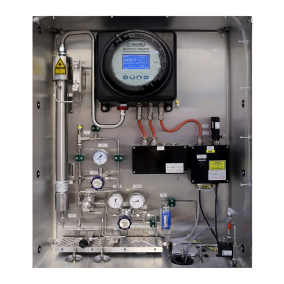
Page 20: Figure 6 Optipeak Sampling System - Typical Indoor Version
OptiPEAK TDL600 User Manual INSTALLATION Ball Valve TP CONNECTIONS Particulate Filter 1/4" NPT(F) Sample Gas Inlet 1/4" NPT(F) Sample Gas Outlet Pressure Regulator 1/4" NPT(F) Bypass Flow Gas Outlet Pressure Gauge 1/4" NPT(F) Drain Pressure Gauge Coalescing & Membrane Filter BV1 Ball Valve Pressure Regulator Particulate Filter... -
Page 21: Figure 8 Optipeak Sampling System - Typical Outdoor Version
OptiPEAK TDL600 User Manual INSTALLATION TP CONNECTIONS Ball Valve 1/4" NPT(F) Sample Gas Inlet 1/4" NPT(F) Sample Gas Outlet Particulate Filter 1/4" NPT(F) Bypass Flow Gas Outlet Pressure Regulator 1/4" NPT(F) Drain 1/4" NPT(F) Vortex Cooler Inlet Pressure Gauge BV1 Ball Valve Pressure Gauge Particulate Filter PR1 Pressure Regulator... -
Page 22: Figure 9 Optipeak Sampling System - Typical Outdoor Version
OptiPEAK TDL600 User Manual INSTALLATION 300.0 MOUNTING HOLES 10mm) 300.0 MOUNTING HOLES 10mm) 316SS NAMEPLATE 316SS NAMEPLATE ENCLOSURE (NOTE 1) ENCLOSURE (NOTE 1) TP05 SIGNAL OUTPUTS CABLE ENTRIES (2 x M20) TP05 SIGNAL OUTPUTS POWER INLET CABLE ENTRY CABLE ENTRIES (M20) (2 x M20) SIZE... -
Page 23: Electrical Connections
OptiPEAK TDL600 User Manual INSTALLATION Electrical Connections All electrical connections to the TDL600 are made through junction boxes JB1 & JB2 (ATEX, IECEx, UKCA and NEC500 Class I, Division 2 versions only). WARNING: Once the mains power connections are made to JB1 the heaters and vortex cooling solenoid (if fitted) will be energized. -
Page 24: Analog Outputs
OptiPEAK TDL600 User Manual INSTALLATION Terminals are marked: Terminal No. Power Supply Live Neutral Earth NOTE: An earth stud is provided in the base of the enclosure. This must be used to earth bond the Sampling System. A power isolator switch is provided on the Power Circuits junction box for local power isolation of the OptiPEAK TDL600 Moisture Analyzer (Main Unit only) for maintenance or servicing. -
Page 25: Modbus Rtu / Rs485 Connection
OptiPEAK TDL600 User Manual INSTALLATION 2.8.5 Modbus RTU / RS485 Connection The TDL600 features an RS485 port for digital communication, and uses a subset of the Modbus RTU protocol. The RS485 connection should be configured with the following parameters: Parameter Value Baud Rate 9600bps... -
Page 26: Sample Conditioning Requirements
OptiPEAK TDL600 User Manual INSTALLATION 2.10 Sample Conditioning Requirements Sample extraction, handling and conditioning techniques are of critical importance to assure optimal performance and reliability of all gas analyzers that accurately quantify specific components within a process gas composition. Michell Instruments' recommendations and requirements in relation to the OptiPEAK TDL600 are outlined below. - Page 27 OptiPEAK TDL600 User Manual INSTALLATION • Particulate/Coalescing Filter (F2): Provides system protection from contamination of entrained liquids and particulates using membrane filtration. • Pressure Regulator 0-4 Bar (PR2): 2nd stage pressure regulation for moisture measurement. • Input Pressure Gauge (PG3): Indicates cell input pressure as set at PR2.
- Page 28 OptiPEAK TDL600 User Manual INSTALLATION To avoid any risk of condensation forming during transportation to the analyzer, and so ensure that the integrity of the sample gas is maintained, the temperature of the sample impulse tubing must be maintained at a temperature above the highest envisaged water dew point.
-
Page 29: Options
OptiPEAK TDL600 User Manual INSTALLATION 2.11 Options 2.11.1 Enclosure Heater Temperature Control (Outdoor systems ONLY) Sampling systems fitted within enclosures are temperature controlled to maintain a constant temperature environment of at least 10 °C (18 °F) above the highest envisaged dew-point temperature, independent of surrounding temperature variations. -
Page 30: Operation
OptiPEAK TDL600 User Manual OPERATION OPERATION Operation of the OptiPEAK TDL600 Sampling System should be carried out in conjunction with, and referring to, this manual, prior to commencing the System Start-Up Procedure (Section 3.1). Before commencing the start-up procedure it is essential to ensure that the installation conforms to the correct hazardous area and local plant standards. -
Page 31: Shut Down Procedure
OptiPEAK TDL600 User Manual OPERATION Ensure the System Drain Needle Valve (NV1) is CLOSED. Ensure the Measurement Cell Pressure Regulators (PR1 & PR2) and Bypass Flow Metering Valve (FM2) are fully CLOSED. Ensure the Measurement Cell Metering Valve (MV1) is fully CLOSED. Slowly OPEN the Gas Inlet Isolation Valve (BV1) to allow sample gas to enter the Sampling System. -
Page 32: User Interface
OptiPEAK TDL600 User Manual OPERATION User Interface The OptiPEAK features a 4.3” color display. 3.3.1 Interface Controls OptiPEAK TDL600 Process Moisture Analyzer Alarms ALARM! >20 TRIPPED 21.4 Dewpt >-10 RTD Temp <5, >50 Dewpoint ISO at Line Pressure Line Pressure -17.5 61.2 °C... -
Page 33: Enter' Key
OptiPEAK TDL600 User Manual OPERATION 3.3.3 ‘ENTER’ Key ENTER Figure 12 'ENTER’ Key ENTER key is used to select or de-select a highlighted item in a menu list. Some parameters, such as the output and alarm minimum and maximum values activate ENTER the numerical entry screen. -
Page 34: Default Settings
OptiPEAK TDL600 User Manual OPERATION Default Settings On initial start up, the TDL600 Regional Setting is set to EU and metric units (i.e. Dew Point to ISO 18453 and ºC) are selected. The Regional Setting can be changed to US (see section 3.7.6.6), this is applies US standard units (i.e. -
Page 35: Menu Structure
OptiPEAK TDL600 User Manual OPERATION Menu Structure Run-Mode Screen Main Menu ENTER Advanced Parameters Display Log Menu About Graph Settings Pressure Contact & Selected Primary Log Period Unit Firmware Info Password Primary 7316 Measurement Parameter Temperature Secondary Log # Info Unit Tertiary Resolution... -
Page 36: Main Menu Screen
OptiPEAK TDL600 User Manual OPERATION Main Menu Screen All instrument operating parameters, logging information, and advanced settings for outputs, alarms and pressure are available through this screen. This screen is accessed by pressing the key from the Run-Mode Screen. Down ( Use the () and ) keys to highlight the page of interest and press the... -
Page 37: Parameters Screen
OptiPEAK TDL600 User Manual OPERATION 3.7.1 Parameters Screen The Parameters Screen controls which measured or calculated parameters are shown on the Run-Mode Screen. ENTER This screen is accessed by pressing the key from the Main Menu Screen. Use the () and Down ( ) keys to highlight the parameter of interest and press ENTER... -
Page 38: Display Screen
OptiPEAK TDL600 User Manual OPERATION 3.7.2 Display Screen The Display Setup Screen controls which units are used for temperature and pressure on the display, alarm, and analog output screens. It also enables the brightness and display resolution to be set. ENTER This screen is accessed by pressing the key from the Main Menu Screen. -
Page 39: Log Menu Screen
OptiPEAK TDL600 User Manual OPERATION 3.7.3 Log Menu Screen The Data Logging Screen allows data-logging to the SD card, which is fitted to the rear of the display PCB. Refer to Section 4.2 for instructions on fitting and removing the SD card. -
Page 40: About Screen
OptiPEAK TDL600 User Manual OPERATION 3.7.4 About Screen The Contact/About Screen shows the current firmware version and company contact information. ENTER This screen is accessed by pressing the key from the Main Menu Screen. Press the key to return to the Run Mode Screen. Contact/About Michell Instruments Web: www.michell.com... -
Page 41: Advanced Settings Screen
OptiPEAK TDL600 User Manual OPERATION 3.7.6 Advanced Settings Screen This screen is accessed by pressing the ENTER key from the Main Menu Screen. Passcode To safeguard against unauthorized adjustment of Advanced Settings options, an entry lock is provided. 7316. The user must first input the access code Down ( ) key selects the digit and the () key changes the value of the... -
Page 42: 3.7.6.1 Outputs Screen
OptiPEAK TDL600 User Manual OPERATION 3.7.6.1 Outputs Screen ENTER This screen is accessed by pressing the key from the Advanced Settings Screen. Down ( Use the () and ) keys to highlight the Output required and press the ENTER key to access. On the Setup Screen use the () and Down (... -
Page 43: 3.7.6.2 Alarms Screen
OptiPEAK TDL600 User Manual OPERATION 3.7.6.2 Alarms Screen ENTER The Alarm Setup Screens are accessed by pressing the key from the Advanced Settings Screen. Down ( Use the () and ) keys to highlight the Alarm required and press the ENTER key to access. - Page 44 OptiPEAK TDL600 User Manual OPERATION Alarm Parameter High, Low Out of Band When the alarm type is set to , or , the parameter can be set to any of the following: Line Pressure Spare input DP ideal Dew Point IGT Dew Point ISO mg/m3 lb/MMscf...
-
Page 45: Figure 24 Typical Alarm Status Indication On The Run-Mode Screen
OptiPEAK TDL600 User Manual OPERATION Fault Alarm A Fault alarm is triggered by any parameter alarm, or by any of the fault conditions below. Fault messages are displayed on the bottom line of the Run-Mode Screen. If more than one fault is active, they are displayed cyclically at two-second intervals. If no faults are active, the message No Faults is displayed. -
Page 46: 3.7.6.3 Inputs Screen
OptiPEAK TDL600 User Manual OPERATION 3.7.6.3 Inputs Screen The Inputs Screen allows access to the Line Pressure Setup Screen, Spare Input Screen and ppm Screen (passcode required). The Line Pressure Setup Screen enables pressure compensation for dew point. A fixed value can be used, or the live value from a pressure transducer if supplied. -
Page 47: Figure 26 Line Pressure Setup Screen
OptiPEAK TDL600 User Manual OPERATION Line Pressure Setup Press the key to return to the Inputs Screen. Line Pressure Setup Screen Figure 26 Parameter Description Switches between fixed pressure input, or live value from pressure sensor Source Available Options: Fixed, Live (4-20 mA) Pressure compensation value when source is set to fixed Fixed Pressure value... -
Page 48: Figure 27 Spare Input Setup Screen
OptiPEAK TDL600 User Manual OPERATION Spare Input Setup Press the key to return to the Inputs Screen. Spare Input Setup Screen Figure 27 Parameter Description Minimum Zero value for the pressure input (4 mA point) Maximum Span value for the pressure input (20 mA point) Enable Available Options: disabled, enabled Table 6... -
Page 49: 3.7.6.4 Clock Screen
OptiPEAK TDL600 User Manual OPERATION 3.7.6.4 Clock Screen The Set Date/Time Screen allows the time and date to be set, which is used when logging to a file. This screen is accessed by pressing the ENTER key from the Advanced Settings Screen. Down ( ) key selects the next digit and the () key changes the value of the... -
Page 50: 3.7.6.5 Modbus Screen
OptiPEAK TDL600 User Manual OPERATION 3.7.6.5 Modbus Screen The Modbus Settings Screen allows the Modbus address and the Baud Rate to be set. Refer to Section 2.8.4 for information about the Modbus / RS485 connection. Refer to Appendix E for a complete Modbus Register listing. This screen is accessed by pressing the ENTER key from the Advanced Settings Screen. -
Page 51: 3.7.6.6 Region Defaults Screen
OptiPEAK TDL600 User Manual OPERATION 3.7.6.6 Region Defaults Screen The Region Defaults Screen allows the user to toggle between EU (metric) and US (imperial/fractional) default parameters and unit presets. ENTER This screen is accessed by pressing the key from the Advanced Settings Screen. ENTER Down ( Press the... -
Page 52: 3.7.6.7 N2-Mode (Measurement Mode) Screen
OptiPEAK TDL600 User Manual OPERATION 3.7.6.7 N2-Mode (Measurement Mode) Screen The N2-Mode (Measurement Mode) Screen puts the TDL600 into N2/field validation mode. The front screen will display ppm O in N as the measurement parameter. None Invalid measurement parameters will change to and display a value (Dewpoint ISO, IGT, lbs/mmscf) and will not be selectable when in this mode. -
Page 53: Enclosure Cover And User Interface
OptiPEAK TDL600 User Manual OPERATION Laser Disabled ESC to return to normal operation Figure 32 Safe Mode (Laser Disabled) Screen Enclosure Cover and User Interface The enclosure cover is part of the flameproof protection for the enclosure and has an IP66 rating. -
Page 54: Maintenance
OptiPEAK TDL600 User Manual MAINTENANCE MAINTENANCE The power to the enclosure must be turned off before any work is carried out in the measurement system enclosure. Observe de-energize durations. Gas line connections to the measurement system must be isolated and de-pressurized before any work commences. Any loose or disturbed pipework or couplings must be leak tested. -
Page 55: Inspection Of The Enclosure Cover
OptiPEAK TDL600 User Manual MAINTENANCE Inspection of the Enclosure Cover Michell Instruments recommends that this procedure is carried out every 12 months, or at any other time that the enclosure lid is removed. Isolate the sample gas supply to the OptiPEAK TDL600. Isolate power to the OptiPEAK TDL600 using the switch on JB1 (ATEX, IECEx, UKCA and NEC500 Class I, Division 2 versions only). - Page 56 OptiPEAK TDL600 User Manual MAINTENANCE Inspect the metal ring and silicon seal from the inside of the lid. Inspect the flame path / threaded joint between the lid and body for damage to the threads. Inspect the gasket for pitting, damage or signs of corrosion. Wipe the screw threads clean of dirt, grit or other foreign bodies.
-
Page 57: Replacement Of The Micro Sd Data Logging Card
OptiPEAK TDL600 User Manual MAINTENANCE Replacement of the Micro SD Data Logging Card Isolate the sample gas supply to the OptiPEAK TDL600. Isolate power to the OptiPEAK TDL600 using the switch on JB1 (ATEX, IECEx, UKCA and NEC500 Class I, Division 2 versions only). Remove the Exd enclosure lid by unscrewing the hex locking screw and turning the lid counter-clockwise until the threads disengage. - Page 58 OptiPEAK TDL600 User Manual MAINTENANCE Disconnect the display data cable by releasing its latch. The micro SD card, is located on the green, rectangular display PCB, in the bottom right hand corner. It may be necessary to use tweezers or a small pair of pliers when fitting a new micro SD card.
-
Page 59: Membrane And Particulate Filter Element Replacement
OptiPEAK TDL600 User Manual MAINTENANCE Membrane and Particulate Filter Element Replacement 4.3.1 Service Intervals The life expectancy of the filter elements is dependent upon operating conditions in each specific application. As a minimum it is recommended that the filter elements be changed every 12 months. - Page 60 OptiPEAK TDL600 User Manual MAINTENANCE Changing the Filter Element Ensure there is no pressure in the housing. Remove the bowl, element retainer and filter element. The disposable coalescing filter element is sealed by compression against a flat surface. Gaskets are not required between the filter element and components of the housing. The element is located by guides which fit the inside diameter of the tube at each end.
-
Page 61: Field Measurement Verification
OptiPEAK TDL600 User Manual MAINTENANCE 4.3.3 Field measurement verification Occasionally, in order to troubleshoot a problem or check the calibration of a TDL600 analyzer, it may be beneficial to use a reference gas to verify that it is reading correctly. The most representative verification check can be carried out using a certified moisture in methane cylinder. -
Page 62: Long-Term Maintenance - Laser Replacement
OptiPEAK TDL600 User Manual MAINTENANCE operate at atmospheric without any back-pressure, however small. Allowing temporary venting of nitrogen test gas direct from the measurement cell outlet should be considered, provided any sampling system connection to a combined vent or flare header can be safely isolated. If the analyzer was set to N2 mode, return the unit to natural gas operation by entering the advanced menu (access code 7316) and toggling N2 mode to “off”. - Page 63 OptiPEAK TDL600 User Manual APPENDIX A Appendix A Technical Specifications Michell Instruments...
-
Page 64: Technical Specification
OptiPEAK TDL600 User Manual APPENDIX A Appendix A Technical Specification Performance Measurement Technology Tunable Diode Laser Spectroscopy (TDLAS) Measurement Range * 1...1000 ppm ±1% of reading > 100 ppm Accuracy * ±1 ppm < 100 ppm Repeatability * < 1 ppm Limit of Detection * <... -
Page 65: Figure 33 Dimensional Drawing - Indoor System Enclosure
OptiPEAK TDL600 User Manual APPENDIX A EMC Directive 2014/30/EU LVD Directive 2014/35/EU Compliance IEC 61010 Part 15 US FCC FDA "Laser Product" Registered (Assigned Accession No.) WEEE and RoHS compliant Laser Class Class 1: IEC/EN 60825-1:2007 Dimensional Drawings Indoor System Enclosure 750.0 25.0 700.0 CRS... -
Page 66: Figure 34 Dimensional Drawing - Outdoor System Enclosure
OptiPEAK TDL600 User Manual APPENDIX A Dimensional Drawings Outdoor System Enclosure 300.0 MOUNTING HOLES 10mm) 316SS NAMEPLATE ENCLOSURE (NOTE 1) TP05 SIGNAL OUTPUTS CABLE ENTRIES (2 x M20) POWER INLET CABLE ENTRY TERMINATION SCHE (M20) SIZE DESCRIPTION EARTH STUD TP04 TP02 TP01 TP03... - Page 67 OptiPEAK TDL600 User Manual APPENDIX B Appendix B Indoor Sampling System Wiring Diagram Michell Instruments...
-
Page 68: Figure 35 Wiring Diagram Indoor System
OptiPEAK TDL600 User Manual APPENDIX B Appendix B Indoor Sampling System Wiring Diagram Wiring Diagram Indoor System Figure 35 97319 Issue 4.6, August 2021... - Page 69 OptiPEAK TDL600 User Manual APPENDIX C Appendix C Outdoor Sampling System Wiring Diagram Michell Instruments...
-
Page 70: Figure 36 Wiring Diagram Outdoor System
OptiPEAK TDL600 User Manual APPENDIX C Appendix C Outdoor Sampling System Wiring Diagram Wiring Diagram Outdoor System Figure 36 97319 Issue 4.6, August 2021... - Page 71 OptiPEAK TDL600 User Manual APPENDIX D Appendix D Flow Diagram Michell Instruments...
-
Page 72: Appendix D Flow Diagram
OptiPEAK TDL600 User Manual APPENDIX D Appendix D Flow Diagram 97319 Issue 4.6, August 2021... - Page 73 OptiPEAK TDL600 User Manual APPENDIX E Appendix E Modbus Holding Register Map Michell Instruments...
-
Page 74: Appendix E Modbus Holding Register Map
OptiPEAK TDL600 User Manual APPENDIX E Appendix E Modbus Holding Register Map All the data values relating to the TDL600 are stored in holding registers. Each of these registers is 16-bits wide. Some of these registers contain instrument specific values e.g. alarm settings etc. Other registers hold specific real time data e.g. - Page 75 OptiPEAK TDL600 User Manual APPENDIX E Michell Instruments...
- Page 76 OptiPEAK TDL600 User Manual APPENDIX E 97319 Issue 4.6, August 2021...
- Page 77 OptiPEAK TDL600 User Manual APPENDIX E Michell Instruments...
- Page 78 OptiPEAK TDL600 User Manual APPENDIX F Appendix F Quality, Recycling, Compliance & Warranty Information 97319 Issue 4.6, August 2021...
-
Page 79: Appendix F Quality, Recycling, Compliance & Warranty Information
OptiPEAK TDL600 User Manual APPENDIX F Appendix F Quality, Recycling, Compliance & Warranty Information Michell Instruments is dedicated to complying to all relevant legislation and directives. Full information can be found on our website at: www.michell.com/compliance This page contains information on the following directives: •... - Page 80 OptiPEAK TDL600 User Manual APPENDIX G Appendix G Analyzer Hazardous Area Certification 97319 Issue 4.6, August 2021...
-
Page 81: Appendix G Hazardous Area Certification
OptiPEAK TDL600 User Manual APPENDIX G Appendix G Hazardous Area Certification The OptiPEAK TDL600 is certified compliant to the ATEX Directive (2014/34/EU), the IECEx scheme and SI 2016 No. 1107 UKCA product marking scheme for use within Zone 1 & 2 Hazardous Areas, and has been assessed as being so by ELEMENT MATERIALS TECHNOLOGY Ltd (Notified Body 2812) and ELEMENT MATERIALS TECHNOLOGY Ltd (Approved Body 0891). -
Page 82: Special Conditions Of Use
OptiPEAK TDL600 User Manual APPENDIX G Special Conditions of Use Do not open when an explosive gas atmosphere may be present. Do not open when energised. External cables shall be compatible with a maximum temperature of 90 °C. Only suitably ATEX / IECEx / UKCA / NRTL certified (as appropriate to the equipment application) cable glands, conduit entry devices and blanking elements shall be used. - Page 83 OptiPEAK TDL600 User Manual APPENDIX H Appendix H Return Document & Decontamination Declaration Michell Instruments...
-
Page 84: Appendix H Return Document & Decontamination Declaration
OptiPEAK TDL600 User Manual APPENDIX H Appendix H Return Document & Decontamination Declaration Decontamination Certificate IMPORTANT NOTE: Please complete this form prior to this instrument, or any components, leaving your site and being returned to us, or, where applicable, prior to any work being carried out by a Michell engineer at your site. - Page 85 OptiPEAK TDL600 User Manual NOTES Michell Instruments...
- Page 86 www.ProcessSensing.com http://www.michell.com...
Need help?
Do you have a question about the Michell Instruments TDL600 and is the answer not in the manual?
Questions and answers