Sign In
Upload
Manuals
Brands
PST Manuals
Measuring Instruments
Michell Instruments TDL600
PST Michell Instruments TDL600 Manuals
Manuals and User Guides for PST Michell Instruments TDL600. We have
1
PST Michell Instruments TDL600 manual available for free PDF download: User Manual
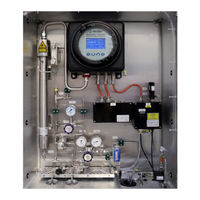
PST Michell Instruments TDL600 User Manual (86 pages)
Process Moisture Analyzer
Brand:
PST
| Category:
Measuring Instruments
| Size: 5 MB
Table of Contents
Table of Contents
4
Safety
7
Electrical Safety
7
Pressure Safety
7
Toxic Materials
7
Repair and Maintenance
7
Calibration (Factory Validation)
7
Safety Conformity
7
Abbreviations
8
Introduction
9
Application
9
Features
9
Theory of Operation
10
Figure 1 Beer Lambert Law
11
Measurement Using a Laser
12
Figure 2 Laser Scan
12
Figure 3 System Block Schematic
13
Installation
14
Unpacking the Instrument
14
Figure 4 Unpacking the TDL600
14
Lifting and Handling
15
Laser Safety
15
Hazardous Area Safety
16
Electrical Safety
17
Equipment Ratings and Installation Details
17
Figure 5 Earthing Stud and Nut Washer Assembly
18
Pressure Safety
19
Basic Installation Guidelines
19
Figure 6 Optipeak Sampling System - Typical Indoor Version
20
Figure 7 Optipeak Sampling System - Typical Indoor Version
20
Figure 8 Optipeak Sampling System - Typical Outdoor Version
21
Figure 9 Optipeak Sampling System - Typical Outdoor Version
22
Electrical Connections
23
Power Connection
23
Analog Outputs
24
Analog Inputs
24
Alarm Relays
24
Modbus RTU / RS485 Connection
25
Environmental Requirements
25
Sample Conditioning Requirements
26
2.10.1 Gas Connections
26
2.10.2 Sample Flow Gas Handling Components
26
Options
29
Enclosure Heater Temperature Control (Outdoor Systems ONLY)
29
Vortex Cooling (Outdoor Systems ONLY)
29
2.11.3 Trace Heated Sample Line
29
Operation
30
Start-Up Procedure
30
Shut down Procedure
31
User Interface
32
Interface Controls
32
Up/Down Arrow Keys
32
Figure 10 User Interface
32
Figure 11 Up/Down Arrow Keys
32
ENTER' Key
33
ESC' Key
33
Description of Measured Parameters
33
Figure 12 'ENTER' Key
33
Figure 13 'ESC' Key
33
Default Settings
34
Advanced Menu Default Settings
34
Menu Structure
35
Figure 14 Menu Structure
35
Main Menu Screen
36
Figure 15 Main Menu Screen
36
Parameters Screen
37
Figure 16 Parameters Screen
37
Table 1 Parameters Screen Parameters
37
Display Screen
38
Figure 17 Display Setup Screen
38
Table 2 Display Setup Screen Parameters
38
Log Menu Screen
39
Figure 18 Data Logging Screen
39
Table 3 Data Logging Screen Parameters
39
About Screen
40
Graph Screen
40
Figure 19 Contact/About Screen
40
Figure 20 Graph Screen
40
Advanced Settings Screen
41
Figure 21 Advanced Settings Screen
41
3.7.6.1 Outputs Screen
42
Figure 22 Output Screens
42
Table 4 Output Screen Parameters
42
3.7.6.2 Alarms Screen
43
Figure 23 Alarm Screens
43
Figure 24 Typical Alarm Status Indication on the Run-Mode Screen
45
3.7.6.3 Inputs Screen
46
Figure 25 Input Screen
46
Figure 26 Line Pressure Setup Screen
47
Table 5 Line Pressure Setup Screen Parameters
47
Figure 27 Spare Input Setup Screen
48
Table 6 Spare Input Setup Screen Parameters
48
3.7.6.4 Clock Screen
49
Figure 28 Set Date/Time Screen
49
Table 7 Set Date/Time Screen Parameters
49
3.7.6.5 Modbus Screen
50
Figure 29 Modbus Settings Screen
50
Table 8 Modbus Screen Parameters
50
3.7.6.6 Region Defaults Screen
51
Figure 30 Region Defaults Screen
51
Table 9 Region Default Parameters
51
3.7.6.7 N2-Mode (Measurement Mode) Screen
52
3.7.6.8 Safe Mode (Laser Disabled) Screen
52
Figure 31 N2-Mode (Measurement Mode) Screen
52
Table 10 N2-Mode Parameters
52
Enclosure Cover and User Interface
53
Figure 32 Safe Mode (Laser Disabled) Screen
53
Maintenance
54
Inspection of the Enclosure Cover
55
Replacement of the Micro SD Data Logging Card
57
Membrane and Particulate Filter Element Replacement
59
Service Intervals
59
Installing the Filter Element and Membrane
59
Field Measurement Verification
61
Long-Term Maintenance - Laser Replacement
62
Technical Specification
64
Figure 33 Dimensional Drawing - Indoor System Enclosure
65
Dimensional Drawings
65
Figure 34 Dimensional Drawing - Outdoor System Enclosure
66
Dimensional Drawings
66
Figure 35 Wiring Diagram Indoor System
68
Appendix B Indoor Sampling System Wiring Diagram
68
Figure 36 Wiring Diagram Outdoor System
70
Appendix C Outdoor Sampling System Wiring Diagram
70
Appendix D Flow Diagram
72
Appendix E Modbus Holding Register Map
74
Appendix F Quality, Recycling, Compliance & Warranty Information
79
Appendix G Hazardous Area Certification
81
Product Standards
81
Product Certification
81
Global Certificates/Approvals
81
Special Conditions of Use
82
Maintenance and Installation
82
Appendix H Return Document & Decontamination Declaration
84
Advertisement
Advertisement
Related Products
PST Michell Instruments Liquidew I.S.
PST Michell Instruments Easidew PRO I.S.
PST MICHELL Instruments Easidew Advanced Online
PST Michell Instruments S8000 -100
PST MICHELL Instruments Easidew PDP Dryer Portable
PST MICHELL Instruments MDM25
PST MICHELL Instruments MDM300
PST Michell Instruments Pura Advanced Online 2
PST Michell Instruments XTP601
PST Michell Instruments XTP601-EX1
PST Categories
Measuring Instruments
Analytical Instruments
Transmitter
Data Loggers
Test Equipment
More PST Manuals
Login
Sign In
OR
Sign in with Facebook
Sign in with Google
Upload manual
Upload from disk
Upload from URL