Table of Contents
Advertisement
Quick Links
Advertisement
Table of Contents

Subscribe to Our Youtube Channel
Related Manuals for PST MICHELL Instruments S8000


Summary of Contents for PST MICHELL Instruments S8000
- Page 1 S8000 Chilled Mirror Hygrometer User Manual 99005 Issue 1 February 2024...
- Page 2 Please fill out the form(s) below for each instrument that has been purchased. Use this information when contacting Michell Instruments for service purposes. Instrument Code Serial Number Invoice Date Location of Instrument Tag Number Instrument Code Serial Number Invoice Date Location of Instrument Tag Number Instrument...
- Page 3 S8000 For Michell Instruments' contact information, please visit www.ProcessSensing.com © 2024 Michell Instruments This document is the property of Michell Instruments Ltd and may not be copied or otherwise reproduced, communicated in any way to third parties, nor stored in any Data Processing System without the express written authorization of Michell Instruments Ltd.
-
Page 4: Table Of Contents
S8000 User Manual Contents Safety ..........................ix Electrical Safety ......................ix Pressure Safety ......................ix Toxic Materials ......................ix Repair and Maintenance ....................ix Calibration ........................ix Safety Conformity ......................ix Abbreviations ........................x Warnings ..........................x INTRODUCTION ....................1 Operating Principle ..................... 2 INSTALLATION ....................3 Safety ........................ 3 Unpacking the Instrument ................... - Page 5 S8000 User Manual Warnings and Faults ..................33 3.3.1 Fault Codes ....................34 3.3.2 Optics Warning ................... 34 Operational Functions ..................35 3.4.1 Operating Cycle ..................35 Operating Guide ....................36 3.5.1 DCC – Dynamic Contamination Control ............36 3.5.2 MAXCOOL Function ..................
- Page 6 S8000 User Manual Figures Figure 1 S8000 ......................1 Figure 2 Operating Principle ..................2 Figure 3 S8000 Packing ....................3 Figure 4 Front Panel ....................6 Figure 5 Rear Panel ....................7 Figure 6 Alarm and Analog Output Connection ............9 Figure 7 USB Port Connection .................11 Figure 8 Ethernet Port ...................11 Figure 9...
-
Page 7: Safety
S8000 User Manual Safety The manufacturer has designed this equipment to be safe when operated using the procedures detailed in this manual. The user must not use this equipment for any other purpose than that stated. Do not apply values greater than the maximum value stated. This manual contains operating and safety instructions, which must be followed to ensure the safe operation and to maintain the equipment in a safe condition. -
Page 8: Abbreviations
S8000 User Manual Abbreviations The following abbreviations are used in this manual: Dynamic Contamination Correction FAST Frost Assurance System Technology MAXCOOL Maximum Sensor Cooling alternating current barg pressure unit (=100 kP or 0.987 atm) gauge bara pressure unit (absolute) °C degrees Celsius °F degrees Fahrenheit... -
Page 9: Introduction
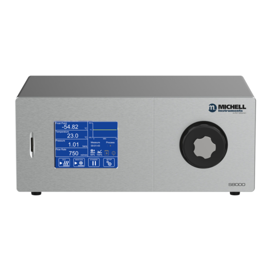
S8000 User Manual INTRODUCTION INTRODUCTION The S8000 is a high precision instrument used for the measurement of dew point in air and other gases. Relative humidity, moisture content, and other calculated parameters based on dew point, pressure and temperature of the sample gas can also be displayed. The S8000 is capable of measuring dew points as low as -60 °C (-76 °F);... -
Page 10: Operating Principle
S8000 User Manual INTRODUCTION Operating Principle The system operates on the chilled mirror principle, whereby a gas sample is passed into the sensor housing and flows over the surface of the chilled mirror contained within. At a temperature dependent upon the moisture content in the gas, and the operating pressure, the moisture in the gas condenses out on the surface of the mirror. -
Page 11: Installation
S8000 User Manual INSTALLATION INSTALLATION Safety It is essential that the installation of the electrical and gas supplies to this instrument is undertaken by competent personnel. Unpacking the Instrument S8000 Packing Figure 3 Open the box (5) and unpack carefully as follows (see Figure 3 ): Remove the accessories box (4). - Page 12 S8000 User Manual INSTALLATION The accessories box should contain the following items: Traceable calibration certificate IEC power cable SD memory storage card Optics cleaning kit Allen Key SMM USB communications cable Pt100 temperature probe (optional) CAT5 ethernet cable (optional) Microscope (optional) If there are any shortages, please notify Michell Instruments immediately (see www.ProcessSensing.com for contact information).
-
Page 13: Operating Requirements
S8000 User Manual INSTALLATION Operating Requirements 2.3.1 Environmental Requirements The S8000 instrument should either be placed on a firm and level surface in a laboratory environment, or mounted into a standard 19" rack. Recommended ambient temperature +20 to +25 °C (+68 to +77 °F) although the instrument will operate, within specification, at elevated ambient temperatures of up to +40 °C (+104 °F), providing the cooling vents are kept clear and unrestricted. -
Page 14: Table 1 Front Panel Controls And Indicators
S8000 User Manual INSTALLATION Front Panel Figure 4 Front Panel Item Name Description Microscope Used to cover the microscope port when not in use. Also to Blanking Plug be used as a key to remove optics window. Exterior housing of the sensor. Sensor Housing Please see Section 5.3 for information about mirror maintenance. -
Page 15: Figure 5 Rear Panel
S8000 User Manual INSTALLATION Rear Panel 8 77 Rear Panel Figure 5 Item Name Description Usually slightly above atmospheric pressure in order to Gas Input Port maintain flow rate over the mirror, but can be up to a maximum of 20 barg depending upon application. Gas Output Port Usually vented to atmosphere. -
Page 16: Rear Panel Connections (All Versions)
S8000 User Manual INSTALLATION Used for communication with the instrument over a network connection. RJ45 Ethernet See Section 3.2.14 for details on how to configure the Socket network settings. See Section 4 for information on using and installing the application software. Flow Control Used to regulate flow through the sensor when pump is in Valve (Optional) -
Page 17: Analog Output Connections
S8000 User Manual INSTALLATION 2.5.2 Analog Output Connections The two analog outputs can be configured to represent any of the directly measured or calculated output parameters. They are provided as 2-wire signals from a 6-way connector located on the rear panel of the instrument . Each of these outputs provide a current loop signal (4...20 mA or 0...20 mA). -
Page 18: Alarm Output Connections
S8000 User Manual INSTALLATION 2.5.3 Alarm Output Connections Two alarm outputs are provided from a terminal block, located on the rear panel of the instrument, as two pairs of potential free, change-over relay contacts. These are PROCESS FAULT designated as a alarm and a alarm. -
Page 19: Usb Communications Port Connector
S8000 User Manual INSTALLATION 2.5.5 USB Communications Port Connector The instrument features a USB port for communication with the application software. The appropriate cable will be supplied with the instrument. Check the orientation of the connector and gently push it into the communications socket (see Figures 6 and 7) . -
Page 20: Connection Of Gas Supplies
S8000 User Manual INSTALLATION 2.5.7 Connection of Gas Supplies POSSIBLE INJURY! The tubing, valves and other apparatus attached to this instrument must be adequate for the maximum pressure which will be applied, otherwise physical injury to the operator or bystander is possible. Before connection or disconnection of the instrument to and from the gas line it is essential to vent the system to atmospheric pressure, otherwise severe injury could result. - Page 21 S8000 User Manual INSTALLATION The sample inlet and outlet connections are 6mm Swagelok tube couplings. The ® gas input connection must be made with 6mm stainless-steel tubing. The gas output connection for most applications can just be exhausted to atmosphere via 300 mm (11.8") of PTFE tubing (1).
-
Page 22: Internal Sample Pump (Optional, For 1 Barg Only)
S8000 User Manual INSTALLATION Internal Sample Pump (optional, for 1 barg only) The internal sample pump can be used to allow measurement of static samples at atmospheric pressure. The pump can be routed in to the sample loop or bypassed, depending on whether it is connected via the external tube link. -
Page 23: Conversion Of S8000 To Rack Mount
S8000 User Manual INSTALLATION Conversion of S8000 to Rack Mount Figure 11 illustrates the method for fitting a rack mount instrument into a standard 19” rack. To fit the unit proceed as follows: Figure 11 Rack Fixing Method Turn the unit on its left end and remove the four screws and washers from the side panel. -
Page 24: Operation
S8000 User Manual OPERATION OPERATION As supplied, the S8000 is ready for operation and a set of default parameters has been installed. This section describes both the general operation of the instrument and the method of setting it up and changing the default parameters (see Appendix C) – should this become necessary. -
Page 25: Instrument Display
S8000 User Manual OPERATION Instrument Display The S8000 features a 5.7” color touch screen display. Initialising When the instrument is switched on, an status bar will be shown while the menu system loads. After the menu system has loaded, the Main Screen will show. Figure 12 Main Screen Michell Instruments... -
Page 26: Main Screen
S8000 User Manual OPERATION 3.2.1 Main Screen READOUTS STABILITY GRAPH READOUTS READOUTS OPERATIONAL STATUS DISPLAY FLOW RATE MAXCOOL / STANDBY / SET UP DCC OFF / MEASURE OPERATE DCC ON Figure 13 Main Screen Layout Name Description Readouts These readouts display measured instrument parameters. (Customizable) See Section 3.2.2 for additional information. -
Page 27: Customizable Readouts
S8000 User Manual OPERATION 3.2.2 Customizable Readouts The three readouts on the Main Screen can be configured by the user to show any of the following parameters: • Dew Point • Temperature • Pressure • % Relative Humidity • • g/kg •... -
Page 28: Operational Status Display
S8000 User Manual OPERATION 3.2.3 Operational Status Display The Operational Status display includes the following: Reports current operational mode. Mode This will either be Measure, Standby, DCC, Hold Maxcool Flood Shows the time (in Hours: Minutes: Seconds) remaining until the Next Mode transition to the next mode of operation. -
Page 29: Setup Menu Screen
S8000 User Manual OPERATION 3.2.4 Setup Menu Screen The Setup Menu is used to adjust the operational parameters of the instrument, change the display setup and start or stop the data-logging feature. Initially, when the Setup Menu Screen is opened, a set of labelled icons is displayed. Touching one of these icons will take you to the appropriate submenu. -
Page 30: 3.2.4.1 Numeric Input
S8000 User Manual OPERATION 3.2.4.1 Numeric Input When entering a numeric value, a virtual keypad will be displayed. Figure 15 Virtual Keyboard The allowable range will initially be shown at the top of the keypad, e.g. 0 50 Some parameters can be disabled by entering a value of 0; this will be indicated by 0[off] ... -
Page 31: Menu Structure
S8000 User Manual OPERATION 3.2.5 Menu Structure LOGGING OUTPUTS ALARM DISPLAY CLOCK INPUTS COMMS EXTENDED SETTINGS Type Interval Output Type Resolution Date Temperature Modbus PRT Mode Select input source Setpoint Parameter Stability Time Address Flood Output Value Recovery Mode Setpoint Temp Unit IP Address Type... -
Page 32: Dcc
S8000 User Manual OPERATION 3.2.6 DCC Screen Figure 17 Parameter Description DCC heating temperature can either be relative to last measured dew point or an absolute temperature. Actual temperature or Δ is defined Type by ‘Setpoint’. Available Input: Relative, Absolute Mirror heating temperature during DCC, either absolute or relative to Setpoint last measured dew point. -
Page 33: Logging
S8000 User Manual OPERATION 3.2.7 LOGGING Logging Screen Figure 18 Parameter Description Changes the interval at which data is recorded Input format: mm:ss – Interval Limits: 00:05...10:00 Indicates status of inserted SD card: No SD Card inserted Ready to log Initialising card SD status indicator... -
Page 34: Outputs
S8000 User Manual OPERATION 3.2.8 OUTPUTS Figure 19 Outputs Screen Parameter Description Output Selector Selects the output to be adjusted Arrows Determines the mA output range Output Type Available Input: 4...20 mA/0...20 mA Assigns the chosen calculated or measured parameter to this output channel Available Input: Dew Point, Temperature, Pressure, % Relative Parameter... -
Page 35: Alarm
S8000 User Manual OPERATION 3.2.9 ALARM Alarm Screen Figure 20 Parameter Description Sets the trip criteria for the process alarm. Type Available Input: Over, Under, In. Band, Out. Band, Off Sets the parameter associated with the process alarm. Available Input: Dew Point, Temperature, Pressure, % Relative Parameter Humidity, g/m , g/kg, ppm... -
Page 36: 3.2.10 Display
S8000 User Manual OPERATION 3.2.10 DISPLAY Figure 21 Display Screen Parameter Description Changes the number of decimal places for all displayed parameters. Resolution Available Input: 1 DP, 2 DP, 3 DP Measurement unit for temperature values Temperature Unit Available Input: ºC, ºF Measurement unit for pressure values Pressure Unit Available Input: kPa, psig, psia, barg, bara... -
Page 37: 3.2.11 Clock
S8000 User Manual OPERATION 3.2.11 CLOCK Figure 22 Clock Screen Parameter Description Date Current date. Time Current time. Table 10 Clock Parameters 3.2.12 Inputs Figure 23 Inputs Screen Parameter Description Changes between temperature input from external Source (Temperature Input) Pt100 or a fixed value. Available Input: Fixed, External Value (If ‘Fixed’... -
Page 38: 3.2.13 Comms
S8000 User Manual OPERATION 3.2.13 Comms Comms Screen Figure 24 Parameter Description Modbus Address Sets the Modbus slave address Setup Access the TCP/IP Network Settings page Table 12 Comms Parameters 3.2.14 Network Settings Figure 25 Network Settings Screen Parameter Description IP Address The IP address of the instrument Subnet Mask... -
Page 39: About (Network Settings)
S8000 User Manual OPERATION 3.2.15 ABOUT (Network Settings) When using an S8000 that is fitted with an Ethernet module this page is accessible via the About Screen. Network Settings Screen Figure 26 Parameter Description IP Address The IP address of the instrument. Subnet Mask The subnet mask that determines what subnet the IP address is on. -
Page 40: 3.2.16 Extended Settings
S8000 User Manual OPERATION 3.2.16 Extended Settings Extended Settings Screen Figure 27 Parameter Description PRT Mode Option not available on this model Sets sensor temperature to +20 °C and initiates an extended DCC if mirror temperature exceeds sensor temperature. See Section 3.5.7 for further Flood Recovery information. -
Page 41: Warnings And Faults
S8000 User Manual OPERATION Warnings and Faults The S8000 contains a comprehensive self-diagnosis system to alert the user whenever there is an issue which could affect the measurement. These alerts are divided into two categories: Warnings: A problem which is not currently affecting the measurement but requires attention. -
Page 42: Fault Codes
S8000 User Manual OPERATION 3.3.1 Fault Codes Name Description Chilled Mirror sensor Pt100 resistance out of Mirror PRT Failure range Remote Temperature probe Pt100 Ambient PRT Failure resistance out of range Chiller PRT Failure Cold finger Pt100 resistance out of range RESERVED Mirror temperature too high Mirror temperature exceeded 130 °C... -
Page 43: Operational Functions
S8000 User Manual OPERATION Operational Functions 3.4.1 Operating Cycle The default parameters set up for the instrument define an operating cycle (see Figure 29 ) . Figure 29 Typical Operating Cycle At initial switch-on, the instrument enters a DCC cycle for 2 minutes. This heats the mirror to a default temperature of +20 °C (+36 °F) above the previously measured value - at the time of switch on this will be ambient temperature. -
Page 44: Operating Guide
S8000 User Manual OPERATION Operating Guide 3.5.1 DCC – Dynamic Contamination Control Dynamic Contamination Control ( ) is a system designed to compensate for the loss of measurement accuracy which results from mirror surface contamination. During the process the mirror is heated to a default temperature of 20 °C above the dew point to remove the condensation which has formed during measurement. -
Page 45: Maxcool Function
S8000 User Manual OPERATION 3.5.2 MAXCOOL Function MAXCOOL function over-rides the dew-point control loop and applies maximum cooling drive to the Peltier heat pump. It can be used to determine: • the lowest temperature the mirror can be driven down to with reference to the sensor body. -
Page 46: Frost Assurance System Technology (Fast)
S8000 User Manual OPERATION 3.5.5 Frost Assurance System Technology (FAST) Theoretically, it is possible for water to exist as a super-cooled liquid at temperatures down to -40 °C (-40 °F). A gas in equilibrium with ice is capable of supporting a greater quantity of water vapor at a given temperature than a gas in equilibrium with liquid water. -
Page 47: Application Software
S8000 User Manual APPLICATION SOFTWARE APPLICATION SOFTWARE Application software which can be used for remote monitoring and data logging is available on the Michell Instruments website. A help file is included within the software for guidance on operation. Michell Instruments... -
Page 48: Maintenance
S8000 User Manual MAINTENANCE MAINTENANCE There are no user-serviceable parts on the S8000, other than the removal and replacement of the AC power supply fuse and cleaning the mirror in the sensor. Safety This equipment operates from power supply voltages that can be lethal and at pressures (depending upon application) that could cause injury. -
Page 49: Fuse Replacement
S8000 User Manual MAINTENANCE Fuse Replacement If the instrument fails to operate after it has been connected to an AC power supply (85... 264 V AC, 47/63 Hz) and switched on, proceed as follows: NOTE: Fuse replacement should be carried out by qualified personnel. If the power supply cable is fitted with a fused plug, switch off the power supply, remove the plug, check and, if necessary, replace the fuse. -
Page 50: Sensor Mirror Cleaning
S8000 User Manual MAINTENANCE Sensor Mirror Cleaning WARNING Before removing the safety strap or opening the sensor housing it is essential to vent the system to atmospheric pressure, otherwise severe injury or damage to the equipment could result. Throughout the life of the instrument, periodic cleaning of the mirror surface and optics window may be required. -
Page 51: Releasing The Optics Window
S8000 User Manual MAINTENANCE Replace the items in the reverse order. Make sure when refitting the optics block to align the gold contacts on the block with the gold contacts on the instrument. Replace the large stainless steel cover, screwing it in firmly but taking care not to overtighten it. -
Page 52: Fitting The Microscope (Optional)
S8000 User Manual MAINTENANCE 5.3.2 Fitting the Microscope (Optional) To observe the frost formation on the chilled mirror surface, an optional microscope (Part No. S8K-RS-MCI) can be provided. The microscope allows direct viewing of the mirror surface, providing assurance that ice crystals have formed and that supercooled water is not present at temperatures below 0 °C. -
Page 53: Good Measurement Practice
S8000 User Manual GOOD MEASUREMENT PRACTICE GOOD MEASUREMENT PRACTICE The S8000 is designed to operate in a flowing gas stream. The sampling chamber, which enables a small sample of gas to be passed over a Peltier chilled, plated copper mirror, is designed to operate at pressures up to 1 barg (14.5 psig) (low pressure version), and up to 20 barg (290 psig) max (high pressure version). -
Page 54: Sampling Hints
S8000 User Manual GOOD MEASUREMENT PRACTICE Sampling Hints Ensuring reliable and accurate moisture measurements requires the correct sampling techniques, and a basic understanding of how water vapor behaves. This section aims to explain the common mistakes and how to avoid them. Sampling Materials –... - Page 55 S8000 User Manual GOOD MEASUREMENT PRACTICE Temperature and Pressure effects As the temperature or pressure of the environment fluctuates, water molecules are adsorbed and desorbed from the internal surfaces of the sample tubing, causing small fluctuations in the measured dew point. Adsorption is the adhesion of atoms, ions, or molecules from a gas, liquid, or dissolved solid to the surface of a material, creating a film.
- Page 56 S8000 User Manual GOOD MEASUREMENT PRACTICE • Accentuate adsorption and desorption effects on the gas passing through the sampling system. • Allow pockets of wet gas to remain undisturbed in a complex sampling system, which will then gradually be released into the sample flow. •...
-
Page 57: Calibration
S8000 User Manual CALIBRATION CALIBRATION Traceability The calibration of this instrument is traceable to national standards. For this reason the instrument can only be calibrated in an accredited e.g. NIST or UKAS accredited, standards laboratory. If these facilities do not exist, the instrument must be returned to the manufacturer, Michell Instruments, or an approved agent (for contact information go to www. -
Page 58: Preparation For Shipping
S8000 User Manual PREPARATION FOR SHIPPING PREPARATION FOR SHIPPING For shipping purposes, the instrument should be packed into its original carton, the latter providing the recommended degree of protection during transit. To prepare the instrument for shipping, proceed as follows. Switch off the instrument and remove the power supply cable. - Page 59 S8000 User Manual APPENDIX A Appendix A Technical Specifications Michell Instruments...
-
Page 60: Appendix A Technical Specifications
S8000 User Manual APPENDIX A Appendix A Technical Specifications Dew-Point Sensor Performance Measurement Technology Chilled Mirror Accuracy* ±0.1 °C (±0.18 °F) Reproducibility ±0.05 °C (±0.09 °F) Measurement Range -60...+40 °Cdp (-76...+104 °Fdp) Operating Pressure Low Pressure Version 0...1 barg / 14.5 psig High Pressure Version 0...20 barg / 290 psig Sample Flow Rate... -
Page 61: Dimensions
S8000 User Manual APPENDIX A Dimensions 178.5 mm 46.0 mm 7.028 ins 1.811 ins 440.0 mm 17.323 ins 338.9 mm 13.343 ins 29.2 mm 1.150 ins Michell Instruments... - Page 62 S8000 User Manual APPENDIX B Appendix B Modbus Register Map 99005 Issue 1, February 2024...
-
Page 63: Appendix B Modbus Register Map
S8000 User Manual APPENDIX B Appendix B Modbus Register Map Register Types Type Description uint16 unsigned 16 bit value uint32 unsigned 32 bit value over two registers Register names ending with _MS contain the upper 16 bits Register names ending with _LS contain the lower 16 bits flags unsigned 16 bit value where each bit represents a flag, value can be a combination of flags float... - Page 64 S8000 User Manual APPENDIX B Address Access Data Type Register Map Definition Max. Min. Default uint16 PRESSURE_UNIT 0 = PSIG 1 = PSIA 2 = BARG 3 = BARA 4 = KPA uint16 DECIMAL_PLACES Instrument Status uint16 OPERATING_MODE 0 = NO_CHANGE 1 = SYSTEM_FAILURE 2 = STANDBY 3 = MEASURE...
- Page 65 S8000 User Manual APPENDIX B Address Access Data Type Register Map Definition Max. Min. Default 0 = Not Fitted 1 = No Card 2 = Ready 3 = Logging 4 = Writing 5 = Mount Error 6 = Write Error 7 = Mounting 8 = Write Protected 9 = Unknown...
- Page 66 S8000 User Manual APPENDIX B Address Access Data Type Register Map Definition Max. Min. Default 0 = off (dry) 1 = on (wet) R|W|F float MOL_WEIGHT_MS 999999.9 28.9645 R|W|F MOL_WEIGHT_LS User configuration – DCC/FAST R|W|F boolean DCC_SETPOINT_MODE 0 = absolute 1 = relative R|W|F int16...
- Page 67 S8000 User Manual APPENDIX B Address Access Data Type Register Map Definition Max. Min. Default 0 = Dewpoint 1 = Temperature 2 = Pressure 3 = %rh 4 = Water content: ppm 5 = Water content: ppm 6 = Mixing ratio 7 = Absolute humidity 8 = Wetbulb 9 = Water vapour pressure...
- Page 68 S8000 User Manual APPENDIX B Address Access Data Type Register Map Definition Max. Min. Default R|W|F uint16 PROCESS_ALARM_TYPE 0 = Off 1 = Over setpoint 2 = Under setpoint 3 = Inside band 4 = Outside band R|W|F float PROCESS_ALARM_HYSTER_MS R|W|F PROCESS_ALARM_HYSTER_LS R|W|F...
- Page 69 S8000 User Manual APPENDIX B Address Access Data Type Register Map Definition Max. Min. Default 0 = English 1 = German 2 = Spanish 3 = French 4 = Italian 5 = Portuguese 6 = USA 7 = Russian 8 = Japanese 9 = Chinese R|W|F uint16...
- Page 70 S8000 User Manual APPENDIX B Address Access Data Type Register Map Definition Max. Min. Default User configuration – Feature Unlock uint32 SECURITY_CODE_MS 4294967295 SECURITY_CODE_LS uint32 FEATURE_CODE_MS 4294967295 FEATURE_CODE_LS uint16 FEATURE_FEEDBACK / RESERVED 65535 Instrument Control 1000 uint16 SET_MODE 1 = Standby 2 = DCC 4 = Maxcool 8 = Cancel maxcool...
- Page 71 S8000 User Manual APPENDIX C Appendix C Default Values Michell Instruments...
-
Page 72: Appendix C Default Values
S8000 User Manual APPENDIX C Appendix C Default Values The default values for the HMI Settings are as follows: Main Page Dew point Middle Temperature Bottom Pressure Flow Fixed Outputs 4...20 mA, dew point, -60...+20 °C 4...20 mA, ppm , 0...3000 4...20 mA, flow, 0...1000 ml Alarm 0 °Cdp... - Page 73 S8000 User Manual APPENDIX D Appendix D Quality, Recycling & Warranty Information Michell Instruments...
-
Page 74: Appendix D Quality, Recycling & Warranty Information
S8000 User Manual APPENDIX D Appendix D Quality, Recycling & Warranty Information Michell Instruments is dedicated to complying to all relevant legislation and directives. Full information can be found on our website at: www.ProcessSensing.com/en-us/compliance This page contains information on the following directives: •... - Page 75 APPENDIX E S8000 User Manual Appendix E Return Document & Decontamination Declaration Michell Instruments...
-
Page 76: Appendix E Return Document & Decontamination Declaration
S8000 User Manual APPENDIX E Appendix E Return Document & Decontamination Declaration Decontamination Certificate IMPORTANT NOTE: Please complete this form prior to this instrument, or any components, leaving your site and being returned to us, or, where applicable, prior to any work being carried out by a Michell engineer at your site. - Page 77 S8000 User Manual NOTES Michell Instruments...
- Page 78 www.ProcessSensing.com...
Need help?
Do you have a question about the MICHELL Instruments S8000 and is the answer not in the manual?
Questions and answers