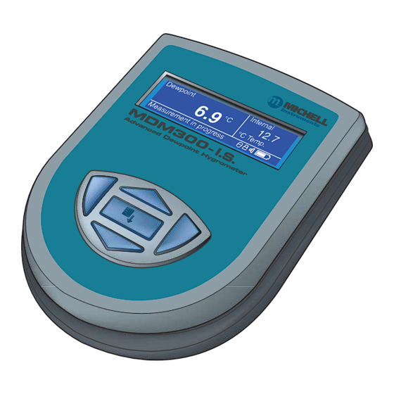
PST MICHELL Instruments MDM300 I.S. User Manual
Advanced dew-point hygrometer
Hide thumbs
Also See for MICHELL Instruments MDM300 I.S.:
- User manual (70 pages) ,
- User manual (25 pages)

Related Manuals for PST MICHELL Instruments MDM300 I.S.


Summary of Contents for PST MICHELL Instruments MDM300 I.S.
- Page 1 MDM300 I.S. Advanced Dew-Point Hygrometer User Manual 97213 Issue 6.4 February 2023 1.800.561.8187 information@itm.com www. .com...
- Page 2 1.800.561.8187 information@itm.com www. .com...
- Page 3 MDM300 I.S. Advanced Dew-Point Hygrometer (for use in hazardous areas) © 2023 Michell Instruments This document is the property of Michell Instruments Ltd and may not be copied or otherwise reproduced, communicated in any way to third parties, nor stored in any Data Processing System without the express written authorization of Michell Instruments Ltd.
- Page 4 MDM300 I.S. User Manual Contents 1.800.561.8187 information@itm.com www. .com...
- Page 5 MDM300 I.S. User Manual Appendices 1.800.561.8187 information@itm.com www. .com...
- Page 6 MDM300 I.S. User Manual Figures Tables 1.800.561.8187 information@itm.com www. .com...
- Page 7 MDM300 I.S. User Manual Safety Electrical Safety NOTE: No battery charger unit other than that supplied with the instrument should be used. NOTE: Do not allow the battery to fully discharge. NOTE: The Um value is less than 250V and must only be connected to a source complying with IEC6050 series, IEC 61010-1 or equivalent standard.
- Page 8 MDM300 I.S. User Manual Abbreviations Warnings Where this hazard warning symbol appears in the following sections it is used to indicate areas where potentially hazardous operations need to be carried out. 1.800.561.8187 information@itm.com www. .com...
- Page 9 MDM300 I.S. User Manual INTRODUCTION INTRODUCTION ° ° 1.800.561.8187 information@itm.com www. .com...
- Page 10 MDM300 I.S. User Manual INTRODUCTION Figure 1 1.800.561.8187 information@itm.com www. .com...
- Page 11 MDM300 I.S. User Manual INTRODUCTION Controls and Indicators Figure 2 1.800.561.8187 information@itm.com www. .com...
- Page 12 MDM300 I.S. User Manual INTRODUCTION Item Panel Description NOTE: The instrument does not need be switched ON in order to charge the internal NiMH battery. NOTE: The hinged rubber protection cover should be kept closed when the connector is not in use. Connection to the battery charger should always be made in a safe area - never in a hazardous area environment...
- Page 13 1.800.561.8187 information@itm.com www. .com...
- Page 14 MDM300 I.S. User Manual INTRODUCTION Instrument Display Figure 3 Item Description Secondary display Battery charge indicator icon NOTE: The icon becomes animated when the charger is connected. Keyboard beep indicator Keyboard lock indicator Datalog status indicator Sensor initializing indicator Primary display Status message display area Table 2 1.800.561.8187...
- Page 15 MDM300 I.S. User Manual INTRODUCTION 1.3.1 Display Units Absolute Humidity • • • Moisture Content • • • Dew Point • • °F • Relative Humidity (%) Mixing Ratio • 1.800.561.8187 information@itm.com www. .com...
- Page 16 MDM300 I.S. User Manual INTRODUCTION 1.3.2 Status Display Indications ‘ < ° 1.800.561.8187 information@itm.com www. .com...
-
Page 17: Installation
MDM300 I.S. User Manual INSTALLATION INSTALLATION Safety It is essential that the installation of the electrical and personnel. Unpacking the Instrument Figure 4 1.800.561.8187 information@itm.com www. .com... -
Page 18: Mdm300 I.s. Accessories
MDM300 I.S. User Manual INSTALLATION MDM300 I.S. Accessories NOTE: On delivery the two large orifice adaptors are fitted into the instrument’s gas ports (1 and 2) as shown in . One small orifice adaptor is provided as a loose spare in the accessory pack (see Section 2.5). Figure 5 1.800.561.8187 information@itm.com... - Page 19 1.800.561.8187 information@itm.com www. .com...
- Page 20 MDM300 I.S. User Manual INSTALLATION Operational Requirements 2.4.1 Environmental Requirements – MDM300 I.S. Instrument 2.4.2 Charger Electrical Requirements Instrument Gas Connections POSSIBLE INJURY! The tubing, valves and other apparatus attached to this instrument must be adequate for the maximum pressure which will be applied, otherwise physical injury to the operator or bystander is possible.
- Page 21 MDM300 I.S. User Manual INSTALLATION 2.5.1 Gas Inlet /Outlet Fittings HIGH PRESSURE! High pressure gases are potentially hazardous. Energy stored in these gases can be released suddenly and with extreme force. High pressure systems should be assembled and operated only by people who have been trained in proper safety practices.
-
Page 22: Battery Charging
MDM300 I.S. User Manual INSTALLATION Battery Charging WARNING: The battery charger must NOT be connected within the hazardous area. The battery charger socket cover MUST be closed when the product is in use within a hazardous area. Figure 9 NOTE: The MDM300 I.S. instrument does not need to be switched on in order to charge the battery. - Page 23 MDM300 I.S. User Manual INSTALLATION WARNING: DO NOT use any other charger than that supplied with this product. The use of any charger other than that supplied for use will invalidate the product warranty. • • • FW 7219 Type Cell-con Stage / Charger Duration...
-
Page 24: Operation
MDM300 I.S. User Manual OPERATION OPERATION High pressure gases are potentially dangerous. POSSIBLE INJURY! The tubing, valves and other apparatus attached to this instrument must be adequate for the maximum pressure which will be applied, otherwise physical injury to the operator or bystander is possible. Preparation for Operation 1.800.561.8187 information@itm.com... -
Page 25: Instrument Start-Up
MDM300 I.S. User Manual OPERATION Instrument Start-Up MDM300 I.S. System Initializing Internal 60.0 Initializing: 04:32 °C Temp. Initializing internal sensor 19.216 Dewpoint Internal ppmv 22.3 10.3 °C °C Temp. Measurement in progress Internal Dewpoint 22.3 °C NOTE: °C Temp. The initialization stage is skipped if the initial dew point is detected to be within 2°C of the dew point when the instrument was switched Figure 10... - Page 26 MDM300 I.S. User Manual OPERATION Overall Menu Structure and Operation 3.3.1 SET-UP Menu • • • NOTE • • • • 3.3.2 Chart Page is not 1.800.561.8187 information@itm.com www. .com...
- Page 27 MDM300 I.S. User Manual OPERATION Scroll Unit Files Page to view Chart Page Main Display (Primary, LOGGING? (only if internal sensor Secondary and Status Windows) available) Logs Page PASSCODE FOR SETUP (on start-up only) =7316 Scroll to Adjust Digit Chart Reset Page PASSCODE To toggle Scroll...
-
Page 28: Set-Up Menu Parameters
MDM300 I.S. User Manual OPERATION SET-UP Menu Parameters 3.4.1 SETTINGS PRIMARY DP AT ATMOS SETTINGS DP/TEMP UNIT °C PRESSURE UNIT Psig GAS TYPE MOL WEIGHT CHART INTERVAL Figure 12 Parameter Description NOTE Table 4 1.800.561.8187 information@itm.com www. .com... - Page 29 MDM300 I.S. User Manual OPERATION 3.4.2 LOGGING > FILE NAME LOGGING PARAMETER DEWP LOG INTERVAL START? STOPPED Figure 13 Parameter Description NOTE: key deletes characters started. NOTE: Only one parameter may be logged at one time started. Table 5 NOTE: If a duplicate file name has been entered an error message will be shown when attempting to start logging.
- Page 30 MDM300 I.S. User Manual OPERATION appropriate sample time should be chosen. The table below can be used as a rough guide: Sample time (sec) Logging duration 3.4.3 BLUETOOTH ENABLE BLUETOOTH NAME MDM300 Figure 14 Parameter Description When Bluetooth is turned ON - a status message * * will be displayed.
- Page 31 MDM300 I.S. User Manual OPERATION 3.4.3.1 Bluetooth Pairing Procedure NOTE: Each digit will be shown only briefly as it is entered and then hidden. NOTE: The name of the COM port allocated, i.e. COM7, will need to be entered when starting the Michell application software.
- Page 32 MDM300 I.S. User Manual OPERATION 3.4.4 CLOCK YEAR CLOCK MONTH HOUR Figure 16 Parameter Description 00 to 99 01 to 12 01 to 31 00 to 23 00 to 59 Table 7 3.4.5 CONTRAST BRIGHTNESS KEY TONE BL TIMEOUT LANGUAGE PRIMARY DISP INTERN Figure 17...
- Page 33 MDM300 I.S. User Manual OPERATION Parameter Description NOTE: This option is only accessible if an external sensor has Table 8 3.4.6 INFO MDM300 I.S. Portable Hygrometer Firmware 36176 Ver 0.01 Sensor serial number E050-035 Sensor next cal due 03/09/12 20 hr Sensor hours used Figure 18 •...
- Page 34 MDM300 I.S. User Manual OPERATION 3.4.7 CHART Page Figure 19 3.4.8 LOG FILES Page Not logging, press ENTER to setup logging Figure 20 1.800.561.8187 information@itm.com www. .com...
- Page 35 MDM300 I.S. User Manual OPERATION 3.4.9 LOGS Page File CR030911 -100.0 0028 26.8 EXT. EXT_DP 26.2 -90.0 0028 INTVAL 05 Sec -80.0 0028 25.9 110903 25.8 -70.0 0028 25.5 123606 -60.0 0028 Figure 21 • • • • • • NOTE: The chart and datalogging are independent functions;...
- Page 36 MDM300 I.S. User Manual OPERATION 3.4.10 CALIBRATION WARNING: These procedures require the use of specialized test equipment and calibration adjustments should only be POINT MDM300 CALIBRATION -100 -100.0 -100.0 -90.0 -90.0 -80.0 -80.0 -70.0 -70.0 -60.0 -60.0 Figure 22 1.800.561.8187 information@itm.com www.
- Page 37 MDM300 I.S. User Manual OPERATION Default Parameters Associated Section Parameter Default Value Reference START? Table 9 1.800.561.8187 information@itm.com www. .com...
-
Page 38: Guide To Measurement And Sampling
MDM300 I.S. User Manual OPERATION Guide to Measurement and Sampling HIGH PRESSURE! High pressure gases are potentially hazardous. Energy stored in these gases can be released suddenly and with extreme force. High pressure systems should be assembled and operated only by people who have been trained in proper safety practices. - Page 39 MDM300 I.S. User Manual OPERATION the MDM300. Refer to the Sample Conditioning section of the Sampling Hints found in Section 4.1. 3.6.1 Measuring at Atmospheric or System Pressure Without a metering valve Figure 24 With one metering valve With two metering valves 1.800.561.8187 information@itm.com www.
- Page 40 MDM300 I.S. User Manual OPERATION 3.6.2 Measurement Guide Measure at Measure at Dew Point Sample Pressure Atmospheric Pressure > 2.5 barg Table 10 Standard Purge (Atmospheric Measurement) using the inlet flow 1.800.561.8187 information@itm.com www. .com...
- Page 41 MDM300 I.S. User Manual OPERATION Standard Purge (Pressure Measurement) outlet flow control valve Enhanced Purge inlet flow control valve 1.800.561.8187 information@itm.com www. .com...
- Page 42 MDM300 I.S. User Manual OPERATION 3.6.3 Conditional Sensor Purge Battery Management WARNING: If complete discharge does occur, then recharge the battery. If this problem is experienced, refer below for a possible solution. 3.7.1 Battery Troubleshooting Problem (NOTE: OLDER FW 7219 MODEL BATTERY CHARGER ONLY). Cause Solution DO NOT leave this 6 V power supply connected to the...
-
Page 43: Good Measurement Practice
MDM300 I.S. User Manual GOOD MEASUREMENT PRACTICE GOOD MEASUREMENT PRACTICE Note: Dew-point is dramatically affected by changes in pressure - in order to ensure the best performance from the instrument it is essential to adequately regulate the sample pressure. Measurement of Dew Points Drier than -70°Cdp Target Dew Point (°C) T100 response time from ambient (hours) 1.800.561.8187... - Page 44 MDM300 I.S. User Manual GOOD MEASUREMENT PRACTICE Sampling Hints Figure 25 1.800.561.8187 information@itm.com www. .com...
- Page 45 MDM300 I.S. User Manual GOOD MEASUREMENT PRACTICE Temperature and Pressure effects 1.800.561.8187 information@itm.com www. .com...
- Page 46 MDM300 I.S. User Manual GOOD MEASUREMENT PRACTICE • • • • • • System design for fastest response times Filtration 1.800.561.8187 information@itm.com www. .com...
-
Page 47: Application Software
MDM300 I.S. User Manual APPLICATION SOFTWARE APPLICATION SOFTWARE ‘ Figure 26 1.800.561.8187 information@itm.com www. .com... - Page 48 1.800.561.8187 information@itm.com www. .com...
- Page 49 MDM300 I.S. User Manual CALIBRATION Calibration Method WARNING: These procedures require the use of specialized test equipment and calibration adjustments should only be carried instrument’s calibration can be lost. Stabilize Stabilize DP REF MDM300 I.S. DP REF MDM300 I.S. Time Time °C Rdg °C...
- Page 50 MDM300 I.S. User Manual CALIBRATION Calibration Correction Method NOTE: Any logging procedure currently in operation must be cancelled before the calibration procedures can be entered. Figure 28 1.800.561.8187 information@itm.com www. .com...
- Page 51 MDM300 I.S. User Manual SHIPPING SHIPPING NOTE: It is not necessary to return any accessories unless they require repair/replacement. Any returned accessories can be packed in the box (3). Before disconnecting the MDM300 I.S. from the gas line it is essential to vent the system to atmospheric pressure, otherwise severe injury could result.
- Page 52 MDM300 I.S. User Manual APPENDIX A 1.800.561.8187 information@itm.com www. .com...
- Page 53 MDM300 I.S. User Manual APPENDIX A Appendix A Performance Operating Conditions 1.800.561.8187 information@itm.com www. .com...
- Page 54 MDM300 I.S. User Manual APPENDIX A Dimensions Figure 30 1.800.561.8187 information@itm.com www. .com...
- Page 55 MDM300 I.S. User Manual APPENDIX B 1.800.561.8187 information@itm.com www. .com...
- Page 56 MDM300 I.S. User Manual APPENDIX B Appendix B Datalog Status Display Figure 31 Status register bit position Table 12 Status register bit position Table 13 1.800.561.8187 information@itm.com www. .com...
- Page 57 MDM300 I.S. User Manual APPENDIX B Status Register Message Details bit in Hex ° ° Table 14 1.800.561.8187 information@itm.com www. .com...
- Page 58 MDM300 I.S. User Manual APPENDIX C 1.800.561.8187 information@itm.com www. .com...
- Page 59 MDM300 I.S. User Manual APPENDIX C Appendix C ATEX/UKCA IECEx North American (cQPSus) 1.800.561.8187 information@itm.com www. .com...
- Page 60 MDM300 I.S. User Manual APPENDIX C Input Terminal Parameters External Sensor Socket Charging Socket Special Conditions of Use Maintenance and Installation 1.800.561.8187 information@itm.com www. .com...
- Page 61 MDM300 I.S. User Manual APPENDIX D 1.800.561.8187 information@itm.com www. .com...
- Page 62 1.800.561.8187 information@itm.com www. .com...
- Page 63 MDM300 I.S. User Manual APPENDIX E 1.800.561.8187 information@itm.com www. .com...
- Page 64 MDM300 I.S. User Manual APPENDIX E Appendix E Quality, Recycling & Warranty Information • • • • • • • • • • • WEEE2 • • 1.800.561.8187 information@itm.com www. .com...
- Page 65 MDM300 I.S. User Manual APPENDIX F 1.800.561.8187 information@itm.com www. .com...
-
Page 66: Return Document & Decontamination Declaration
APPENDIX F MDM300 I.S. User Manual Appendix F Return Document & Decontamination Declaration IMPORTANT NOTE: Please complete this form prior to this instrument, or any components, leaving your site and being returned to us, or, where applicable, prior to any work being carried out by a Michell engineer at your site. - Page 67 MDM300 I.S. User Manual NOTES: 1.800.561.8187 information@itm.com www. .com...
- Page 68 1.800.561.8187 information@itm.com www. .com...
Need help?
Do you have a question about the MICHELL Instruments MDM300 I.S. and is the answer not in the manual?
Questions and answers