
Related Manuals for PST Michell Instruments Liquidew I.S.


Summary of Contents for PST Michell Instruments Liquidew I.S.
- Page 1 Liquidew I.S. Process Moisture Analyzer User Manual 97092 Issue 5.3 September 2021...
- Page 2 Please fill out the form(s) below for each instrument that has been purchased. Use this information when contacting Michell Instruments for service purposes. Product Name Order Code Serial Number Invoice Date Installation Location Tag Number Product Name Order Code Serial Number Invoice Date Installation Location Tag Number...
- Page 3 Liquidew I.S. Process Moisture Analyzer For Michell Instruments' contact information please go to www.michell.com © 2021 Michell Instruments This document is the property of Michell Instruments Ltd and may not be copied or otherwise reproduced, communicated in any way to third parties, nor stored in any Data Processing System without the express written authorization of Michell Instruments Ltd.
-
Page 4: Table Of Contents
Liquidew I.S. User Manual Contents Safety .............................vii Electrical Safety ........................vii Pressure Safety ........................vii Toxic Materials .........................vii Repair and Maintenance......................vii Calibration ..........................vii Safety Conformity ........................vii Abbreviations ..........................viii Warnings ............................viii INTRODUCTION ......................1 Performance Features ..................... 2 Applications ........................2 Theory of Operation ...................... - Page 5 Liquidew I.S. User Manual System Fault Alarm Set-Up .....................40 3.8.1 Minimum Dew-Point Value for the Fault Alarm ............40 3.8.2 Maximum Dew-Point Value for the Fault Alarm ............40 3.8.3 Minimum Temperature Value for the Fault Alarm ............41 3.8.4 Maximum Temperature Value for the Fault Alarm ............41 Alarm Setting ........................42 3.9.1 Alarm Set-Point Adjustment ..................42...
- Page 6 Liquidew I.S. User Manual Appendices Appendix A Technical Specifications ..................47 Dimensional Drawings ................49 Appendix B Serial Communications ..................51 Appendix C Modbus RTU Comms .....................56 Appendix D Hazardous Area Certification ..................59 Product Standards .................59 Product Certification................59 Global Certificates/Approvals ..............59 Terminal Parameters ................60 Special Conditions ..................60 Maintenance and Installation ..............60 Appendix E...
-
Page 7: Safety
Liquidew I.S. User Manual Safety The manufacturer has designed this equipment to be safe when operated using the procedures detailed in this manual. The user must not use this equipment for any other purpose than that stated. Do not apply values greater than the maximum value stated. This manual contains operating and safety instructions, which must be followed to ensure the safe operation and to maintain the equipment in a safe condition. -
Page 8: Abbreviations
Liquidew I.S. User Manual Abbreviations The following abbreviations are used in this manual: Ampere alternating current barg pressure unit (=100 kP or 0.987 atm) gauge °C degrees Celsius °F degrees Fahrenheit direct current dew point gallons per minute ” inch(es) lbf-ft pound force per foot l/min... -
Page 9: Introduction
Liquidew I.S. User Manual INTRODUCTION INTRODUCTION The Liquidew I.S. Process Moisture Analyzer is a continuous, on-line instrument for the measurement of absolute moisture content in a liquid. It is designed to fulfil a wide range of applications and provide for the monitoring and/or control of moisture in liquids. -
Page 10: Performance Features
Liquidew I.S. User Manual INTRODUCTION Performance Features • State-of-the-art ceramic moisture sensor with chemically inert materials coupled with physical resilience provides long-term reliability in the most arduous applications. Robust construction is exceedingly durable in liquid. Not affected by pressure shocks. •... -
Page 11: Theory Of Operation
Liquidew I.S. User Manual INTRODUCTION Theory of Operation Reliable and robust sensor design is fundamental to achieving accurate measurement of moisture in liquids over a long period of time. Proprietary thick- and thin-film techniques are applied in the Michell Ceramic Moisture Sensor. Base metal layers, on semi-conductor grade ceramic substrate, sense dissolved moisture within the sample liquid flow. -
Page 12: System Components
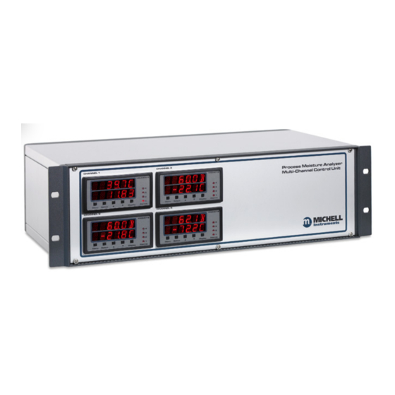
Liquidew I.S. User Manual INTRODUCTION System Components The Liquidew I.S. Process Moisture Analyzer consists of: • the sensor assembly • the control unit Sensor Assembly Control Unit (Up to four channels can have any combination of Liquidew I.S. and Promet I.S.*) Temperature transmitter Sensor block Dew-point transmitter... -
Page 13: User Interface
Liquidew I.S. User Manual INTRODUCTION 1.4.1 User Interface The Liquidew I.S. user interface is located on the control unit. There is a two-line, six digit (15 segment) LED display and four alarm indicators. Five push-button function keys facilitate data display, parameter setting and system adjustment. - 1 9 C Figure 4 User Interface... - Page 14 Liquidew I.S. User Manual INTRODUCTION • key: The key is used to scroll down through pages in the top and sub-level menus and to decrease values in sub-level menus. • Display Display key is used to change the display unit (see Section 3.2.2).
-
Page 15: Power Supply And Input/Output Signal
Liquidew I.S. User Manual INTRODUCTION 1.4.2 Power Supply and Input/Output Signal The terminal blocks for the power supply, signal input, signal output and alarm output are located on the back panel of the control unit (as shown in Figure 9) . •... -
Page 16: Sampling System
Liquidew I.S. User Manual INTRODUCTION Sampling System The Liquidew I.S. requires a clean sample of the process liquid that meets the temperature, pressure and flow requirements of the transmitter. The design of the sampling system will depend on the specific application. The requirements for the sample liquid going into the sensor block are as follows: •... -
Page 17: Installation
Liquidew I.S. User Manual INSTALLATION INSTALLATION It is essential that the installation of the electrical and liquid supplies to this analyzer be undertaken by suitably qualified personnel. Unpacking the Analyzer Unpack carefully as follows: Remove the accessories (if ordered). If no accessories have been ordered the delivery should contain following items: •... -
Page 18: Operating Requirements
Liquidew I.S. User Manual INSTALLATION Operating Requirements 2.2.1 Environmental Requirements The Liquidew I.S. sensor assembly is intrinsically safe and designed to be installed on- site, indoors or outdoors, directly at the point of measurement within a Hazardous Area. The sensor assembly is ATEX, IECEx and certified. -
Page 19: Figure 6 Rack Mounting Method
Liquidew I.S. User Manual INSTALLATION Figure 6 Rack Mounting Method Figure 6 illustrates the general method for fitting a rack mount instrument into a standard 19” rack. To fit the unit proceed as follows: Remove all terminal blocks for the electrical connections. If necessary, remove any covers from the rack cabinet to gain access to the rear and side. -
Page 20: Mounting The Liquidew I.s. Sensor Assembly Into The Sampling System
Liquidew I.S. User Manual INSTALLATION 2.3.2 Mounting the Liquidew I.S. Sensor Assembly into the Sampling System HIGH PRESSURE! High pressure liquids are potentially hazardous. Energy stored in these liquids can be released suddenly and with extreme force. High pressure systems should be assembled and operated only by people who have been trained in proper safety practices. - Page 21 Liquidew I.S. User Manual INSTALLATION The temperature transmitter has a 6mm diameter probe. It is suitable for installing into the 1/8” NPT female port at the other end of the sensor block, by using the Swagelok 6mm to 1/8” NPT, ordering code SS- ®...
-
Page 22: Sampling System Installation
Liquidew I.S. User Manual INSTALLATION 2.3.3 Sampling System Installation HIGH PRESSURE! High pressure liquids are potentially hazardous. Energy stored in these liquids can be released suddenly and with extreme force. High pressure systems should be assembled and operated only by people who have been trained in proper safety practices. -
Page 23: Wiring
Liquidew I.S. User Manual INSTALLATION Wiring These tasks are to be undertaken only by suitably qualified personnel. All the connections to the rear panel are electrical connections. Exercise due caution, particularly when connecting to external alarm circuits which could be at high potential. -
Page 24: Control Unit Wiring
Liquidew I.S. User Manual INSTALLATION 2.4.2 Control Unit Wiring The electrical connections are located at the rear panel of the control unit. There are spaces for four individual channels. HAZARDOUS AREA INFORMATION: The only connections on the control unit which can take cables from hazardous area are the connectors labelled SENSOR INPUTS ALL OTHER CONNECTORS MUST NOT BE CONNECTED TO... -
Page 25: Figure 9 Control Unit Electrical Connections
Liquidew I.S. User Manual INSTALLATION Power input socket and switch 85 to 265 VAC version Power input connector block 10 to 72 VDC version SENSOR INPUTS Dew Point Temp/Pres. Sensor signal input ALARMS SP2 SP4 SP1 SP3 NO NC COM NO NO NC COM NO ... -
Page 26: 2.4.2.1 Power Supply Input Connection
Liquidew I.S. User Manual INSTALLATION 2.4.2.1 Power Supply Input Connection 85...265 V AC The AC power supply connection is a push fit socket labelled POWER INPUT as shown below. POWER INPUT Socket IEC connector Figure 10 POWER INPUT Socket The method of connection is as follows: Turn off the AC power. -
Page 27: Figure 11 Power Input Connector Block
Liquidew I.S. User Manual INSTALLATION 10...72 V DC If a DC power supply version is ordered it will come with a 3-way push fit connector block labelled POWER INPUT as shown below: POWER INPUT socket Terminal bock Figure 11 POWER INPUT Connector Block The method of connection is as follows: Turn off the power. -
Page 28: 2.4.2.2 Sensor Signal Input Connection
Liquidew I.S. User Manual INSTALLATION 2.4.2.2 Sensor Signal Input Connection HAZARDOUS AREA INFORMATION Cables from transmitters mounted in hazardous areas can be connected directly to the SENSOR INPUTS connector block. There are built-in Galvanic I.S. barriers for all connections made to this connector block. Refer to ATEX/QPS/IECEx certificates for the dew-point and temperature transmitters’... -
Page 29: 2.4.2.3 Analog Output Connection
Liquidew I.S. User Manual INSTALLATION 2.4.2.3 Analog Output Connection Two analog output ports are provided for moisture content signal and temperature signal respectively. They are connected via a single 3-way push fit connector block OUTPUT labelled as shown below. OUTPUT ... -
Page 30: 2.4.2.4 Alarm Output Connection
Liquidew I.S. User Manual INSTALLATION 2.4.2.4 Alarm Output Connection Four alarm output ports are provided and are connected to the instrument via a single 8-way push fit connector block labelled ALARMS as shown below. ALARMS socket Terminal bock Figure 14 ALARM Connector Block Alarm 1 (connection labelled as SP1) and Alarm 2 (connection labelled as SP2) are Form... -
Page 31: 2.4.2.5 Rs485 Port Connection
Liquidew I.S. User Manual INSTALLATION Alarm 3 (connection labelled as SP3) and Alarm 4 (connection labelled as SP4) are Form A (single pole, single throw, normally open) relays. The method of connection is as follows: Strip back the wires of the Alarm 3 cable, exposing approximately 6mm (0.2”) - the use of crimps/wire ferrules is recommended. -
Page 32: Sensor Assembly Wiring
Liquidew I.S. User Manual INSTALLATION 2.4.3 Sensor Assembly Wiring NOTE: If the analyzer has been ordered with a sampling system, the Liquidew I.S. sensor assembly will be factory-wired to the junction box. In that case disregard the following instructions and go to Section 3. 2.4.3.1 Dew-point Transmitter Wiring HAZARDOUS AREA INFORMATION The dew-point transmitter (Easidew PRO I.S.) is certified... -
Page 33: Figure 15 Crimped Wires
Liquidew I.S. User Manual INSTALLATION Preparation of the Sensor Cable In order to comply with hazardous area certification of the product it is essential that the crimps/wire ferrules supplied must be attached on to any cable installed into the connector. As shown in Figure 15 below, the crimps/wire ferrules should be applied so that there is no possibility of a conductor strand of a core becoming free. -
Page 34: Figure 18 Dew-Point Transmitter Pin Assignment Drawing
Liquidew I.S. User Manual INSTALLATION Ensure that the outer diameter of the selected cable is matched to an EExe M20 cable gland (5). Unscrew the cable gland (5) and slide the cable through the cable gland (5) and into the terminal housing (1) through the cable entry (3). -
Page 35: 2.4.3.2 Temperature Transmitter Wiring
Liquidew I.S. User Manual INSTALLATION 2.4.3.2 Temperature Transmitter Wiring HAZARDOUS AREA INFORMATION The temperature transmitter is certified intrinsically safe for use in Hazardous areas by TRL and is covered by EC-Type examination certificate TRAC09ATEX11232X. The instrument conforms to the standards EN60079-0:2006, En60079- 11:2007, EN60079-26:2007, EN61241-0:2006, EN61241- 11:2006 certification code II 1 G Ex ia IIC T4 Ga, Ex iaD 20 T135 °C Da, Tamb -20 °C to +85 °C... -
Page 36: Figure 20 Temperature Transmitter Pin Assignment Drawing
Liquidew I.S. User Manual INSTALLATION Connect the signal cable leads to the terminals on the terminal block (4) in accordance with the following pin-assignment drawing. Pin designations are marked adjacent to each pin. SENSOR INPUTS Block Dew Point Temp Supply + 4-20 mA lead 4-20 mA - 4-20 mA lead... -
Page 37: Operation
Liquidew I.S. User Manual OPERATION OPERATION Preparation Before applying power and beginning sample flow ensure that the system has been properly installed following the instructions in Section 2 and that all sample connections are tight and leak free. Check that the wiring has been correctly completed. -
Page 38: Powering-Up The Analyzer
Liquidew I.S. User Manual OPERATION 3.2.2 Powering-up the Analyzer For the AC power supply version of the Liquidew I.S., turning on the power switch on the back panel of the control unit will power-up the control unit and the two transmitters. There is no power switch for the DC power supply version. -
Page 39: Sample Flow Start-Up
Liquidew I.S. User Manual OPERATION Whenever the Display key is pressed, the bottom line of the display will scroll once with the new moisture measurement unit (Moisture/Dew Point) before it shows the readings. NOTE: After the display units are set they will remain the same even if the analyzer power is turned off and on again. -
Page 40: Menu Structure
Liquidew I.S. User Manual OPERATION Menu Structure The Liquidew I.S. main menu has a two level menu structure. There are three sub- LIQUID SETUP, OUTPUT SETUP FAULT SETUP ALARM SETTINGS menus - . The are not in the main menu and are accessed separately. These are described in detail in following sections. -
Page 41: Figure 22 Menu Maps
Liquidew I.S. User Manual OPERATION CHANGE UNITS Display MAIN READING Select BRIGHTNESS ADJUSTMENT PAGE Select Select Menu SP_1 CHANGE MAIN MENU Select SETTINGS SP_2 ALARM SETTING MENU Select SP_3 Select SP_4 Select Select Source Select SPC_1 000-high 100-low Select Select... -
Page 42: Main Reading Page
Liquidew I.S. User Manual OPERATION Main Reading Page The Main Reading Page is the default screen shown after turning the instrument on. It will display the units of measurement selected by the user (see Section 3.2.2). Liquid Set-Up The saturation concentration values of the sample liquid need to be specified for calculation from the measured water dew point (°C/°F), and the sample temperature (°C/°F), to the moisture content (ppm... -
Page 43: User-Defined Liquid
Liquidew I.S. User Manual OPERATION 3.5.2 User-Defined Liquid If the process liquid is not listed the user can define their own liquid solubility profile by entering the value (10 pre-set temperature points, over the range 0...+60 °C (32...+140 °F)) for that particular liquid. There are two user-defined liquids available and these are named USER 1 and USER 2. -
Page 44: Liquid Mixing
Liquidew I.S. User Manual OPERATION 3.5.3 Liquid Mixing The user can define the solubility profile for a liquid by mixing any two liquids from the liquid list, including USER 1 and USER 2, with an editable ratio. LIQUID SETUP In the liquid list in the sub menu, use the ... - Page 45 Liquidew I.S. User Manual OPERATION Change the selection by scrolling through the list using the and keys. When the required second liquid is on the display press the Select to confirm. The display will then show the mixing ratio for this selected second liquid.
-
Page 46: Analog Output 1 (Moisture Content Or Dew Point - User-Selectable)
Liquidew I.S. User Manual OPERATION Analog Output 1 (Moisture Content or Dew Point - User-Selectable) The source and scale of the 4...20 mA output can be configured in the OUTPUT SETUP menu. From the Main Reading Page, press Menu to enter the main menu. Use the key to OUTPUT SETUP scroll to the option. -
Page 47: Output Range Zero Value Settings
Liquidew I.S. User Manual OPERATION 3.6.2 Output Range ZERO Value Settings 0. 0 0 Z E R O ZERO Use the and keys to adjust the value. Select Press the key to confirm. The display will then change to the next SPAN parameter, the point of the output range. -
Page 48: System Fault Alarm Set-Up
Liquidew I.S. User Manual OPERATION System Fault Alarm Set-Up There are four conditions for the system fault alarm which can be configured in the FAULT SETUP sub menu. NOTE: If any of the fault alarm conditions occur during system Analog output 1 Analog operation will rise to 21 mA for both high and low errors. -
Page 49: Minimum Temperature Value For The Fault Alarm
Liquidew I.S. User Manual OPERATION 3.8.3 Minimum Temperature Value for the Fault Alarm 0. 0 C M I N _ T Use the and keys to adjust the minimum temperature value. Select Press the key to confirm. The display will then show the fourth fault alarm parameter which is the maximum temperature value. -
Page 50: Alarm Setting
Liquidew I.S. User Manual OPERATION Alarm Setting There are 4 built-in alarm relays which can be configured independently. From the Main Select Reading Page, press and hold the key then press the key to enter the ‘ALARM SETTING’ page. 0. -
Page 51: Alarm Type Selection
Liquidew I.S. User Manual OPERATION 3.9.2 Alarm Type Selection The alarm type can be selected in the Alarm Control Setting page. Select From the Main Reading Page, press and hold the key then press the key to enter the ‘ALARM SETTING’ page. Press the key until SPC_1 is shown. The alarm can be activated above or below the Alarm Set Points by setting the control code. -
Page 52: Alarm Source Selection
Liquidew I.S. User Manual OPERATION 3.9.3 Alarm Source Selection The alarm source can be also selected in the Alarm Control Setting page. Select From the Main Reading Page, press and hold the key then press the key to enter the ‘ALARM SETTING’ page. Press the key until SPC_1 is shown. RESULT DP_C TEMP_C... -
Page 53: Display Brightness Adjustment
Liquidew I.S. User Manual OPERATION 3.10 Display Brightness Adjustment The brightness of the display can be adjusted from the ‘BRIGHTNESS ADJUSTMENT’ page. From the Main Reading Page, press and hold the Select key then press to enter the ‘BRIGHTNESS ADJUSTMENT’ page. B R I Use the ... - Page 54 Liquidew I.S. User Manual APPENDIX A Appendix A Technical Specifications 97092 Issue 5.3, September 2021...
-
Page 55: Appendix A Technical Specifications
Liquidew I.S. User Manual APPENDIX A Appendix A Technical Specifications Sensors Sensor Technology Michell Ceramic Moisture Sensor Sensor Version Easidew PRO I.S. 0.001...1000 ppm Higher range on request Measurement Range Actual range dependent on solubility of sample fluid Calibration Range -100...+20 °Cdp (-148...+68 °Fdp) Dew point: ±1 °C between –59.9 &... - Page 56 Liquidew I.S. User Manual APPENDIX A 19” sub rack unit Enclosure Dimensions: 132 x 483 x 375mm (5 x 19 x 14.75”) (h x w x d) (100mm (4”) minimum rear clearance depth for cables and vents) Operating Environment Indoor, safe area, 0...+50 °C (+32...+122 °F), < 90% RH Premium Sampling Systems 304 stainless steel (EN1.4301) enclosure Option for complete enclosure in 316 stainless steel (EN1.4401)
-
Page 57: Figure 23 Dimensional Drawings
Liquidew I.S. User Manual APPENDIX A Sample port 1/8” NPT (F) Dimensional Drawings 20mm (0.8”) 375mm + 100mm for cable clearance (14.75” + 3.9”) CHANNEL 1 CHANNEL 3 CHANNEL 2 CHANNEL 4 483mm (19”) ... - Page 58 Liquidew I.S. User Manual APPENDIX B Appendix B Serial Communications 97092 Issue 5.3, September 2021...
-
Page 59: Appendix B Serial Communications
Liquidew I.S. User Manual APPENDIX B Appendix B Serial Communications To communicate with the monitor: • Connect to the serial port using the wiring defined below. • Set the address of the monitor using the front panel. • Set the desired communication protocol (ASCII or Modbus RTU) via the front panel or over the serial interface. - Page 60 Liquidew I.S. User Manual APPENDIX B Setting the Address of the Monitor This procedure needs to be done for either ASCII or MODBUS RTU protocols. a. Press the Select and keys simultaneously to display the BRI (brightness) menu. b. Press the Select key again to display the CAL (calibration) menu.
- Page 61 Liquidew I.S. User Manual APPENDIX B Register Map: Function Register Name Texmate ASCII Modbus RTU MOISTURE RESULT 40515/40516 DEWPOINT_C 40517/40518 TEMPERATURE_C 40519/40520 DEWPOINT_F 40521/40522 TEMPERATURE_F 40523/40524 LAST_VIEW TOTAL1 40529/40530 INPUT_VALUE TOTAL2 40531/40532 cur_table USER_MEMORY_1 5121 45121 UpdateFlag USER_MEMORY_3 5123 45123 MIN_DP USER_MEMORY_4 5124...
- Page 62 Liquidew I.S. User Manual APPENDIX B MODBUS RTU Once the protocol has been set the monitor will communicate in accordance with the standard Modbus RTU protocol. Read Holding Registers command should be used to read the registers listed in the register map.
- Page 63 Liquidew I.S. User Manual APPENDIX C Appendix C Modbus RTU Comms Michell Instruments...
-
Page 64: Appendix C Modbus Rtu Comms
Liquidew I.S. User Manual APPENDIX C Appendix C Modbus RTU Comms Accessing locked codes on Liquidew I.S. monitor (turning off “code blanking”) WARNING: It is recommended that “code blanking” is switched back ON after making any required changes to the configuration codes. - Page 65 Liquidew I.S. User Manual APPENDIX C Michell Instruments...
- Page 66 Liquidew I.S. User Manual APPENDIX D Appendix D Hazardous Area Certification 97092 Issue 5.3, September 2021...
-
Page 67: Appendix D Hazardous Area Certification
Liquidew I.S. User Manual APPENDIX D Appendix D Hazardous Area Certification The Liquidew I.S. Process Moisture Analyzer utilizes the Easidew PRO I.S. dew-point transmitter The Easidew PRO I.S is certified compliant to the ATEX Directive (2014/34/EU), the IECEx scheme and SI 2016 No. 1107 UKCA product marking scheme for use within Zone 0, 1 and 2 Hazardous Areas and has been assessed as being so by CML Bv Netherlands (Notified Body 2776) and EUROFINS CML UK (Approved Body 2503). -
Page 68: Terminal Parameters
Liquidew I.S. User Manual APPENDIX D Terminal Parameters = 28 V = 93 mA = 820 mW = 37 nF Special Conditions The wiring connections to the free socket must be made via crimped connectors in such a way that all the strands of the wire used are held securely by the crimp. - Page 69 Liquidew I.S. User Manual APPENDIX E Appendix E System Drawings Michell Instruments...
-
Page 70: Appendix E System Drawings
Liquidew I.S. User Manual APPENDIX E Appendix E System Drawings Baseefa Approved System Drawing 97092 Issue 5.3, September 2021... -
Page 71: Qps Approved System Drawing
Liquidew I.S. User Manual APPENDIX E QPS Approved System Drawing Michell Instruments... - Page 72 Liquidew I.S. User Manual APPENDIX F Appendix F Quality, Recycling & Warranty Information 97092 Issue 5.3, September 2021...
-
Page 73: Appendix F Quality, Recycling & Warranty Information
Liquidew I.S. User Manual APPENDIX F Appendix F Quality, Recycling & Warranty Information Michell Instruments is dedicated to complying to all relevant legislation and directives. Full information can be found on our website at: www.michell.com/compliance This page contains information on the following directives: •... - Page 74 Liquidew I.S. User Manual APPENDIX G Appendix G Return Document & Decontamination Declaration 97092 Issue 5.3, September 2021...
-
Page 75: Appendix G Return Document & Decontamination Declaration
Liquidew I.S. User Manual APPENDIX G Appendix G Return Document & Decontamination Declaration Decontamination Certificate IMPORTANT NOTE: Please complete this form prior to this instrument, or any components, leaving your site and being returned to us, or, where applicable, prior to any work being carried out by a Michell engineer at your site. - Page 76 www.ProcessSensing.com http://www.michell.com...
Need help?
Do you have a question about the Michell Instruments Liquidew I.S. and is the answer not in the manual?
Questions and answers