Table of Contents
Advertisement
Quick Links
Advertisement
Table of Contents

Subscribe to Our Youtube Channel
Related Manuals for PST MICHELL Instruments MDM300


Summary of Contents for PST MICHELL Instruments MDM300
- Page 1 MDM300 Advanced Dew-Point Hygrometer User Manual 97122 Issue 16.2 June 2022...
- Page 2 Please fill out the form(s) below for each instrument that has been purchased. Use this information when contacting Michell Instruments for service purposes. Product Name Order Code Serial Number Invoice Date Installation Location Tag Number Product Name Order Code Serial Number Invoice Date Installation Location Tag Number...
- Page 3 MDM300 Advanced Dew-Point Hygrometer For Michell Instruments' contact information please go to www.michell.com © 2022 Michell Instruments This document is the property of Michell Instruments Ltd and may not be copied or otherwise reproduced, communicated in any way to third parties, nor stored in any Data Processing System without the express written authorization of Michell Instruments Ltd.
-
Page 4: Table Of Contents
MDM300 User Manual Contents Safety ..........................vii Electrical Safety ......................vii Pressure Safety ......................vii Toxic Materials ......................vii Repair and Maintenance ....................vii Calibration ........................vii Safety Conformity .......................vii Abbreviations ........................viii Warnings .......................... viii INTRODUCTION ....................1 Controls and Indicators ..................3 Function Keys ..................... 5 1.2.1 Enter Key ..................... - Page 5 MDM300 User Manual 3.4.10 LOGS Page ....................31 3.4.11 CALIBRATION ..................... 32 Default Parameters ................... 33 Guide to Measurement and Sampling ..............34 3.6.1 Measuring at Atmospheric or System Pressure ..........35 3.6.2 Measurement Guide ..................36 3.6.3 Conditional Sensor Purge ................38 Battery Management ..................
- Page 6 MDM300 User Manual Figures Figure 1 MDM300 Advanced Dew-Point Hygrometer ...........2 Figure 2 User Connections, Controls and Indicators ............3 Figure 3 Instrument Display ..................6 Figure 4 Packing Method ..................9 Figure 5 Gas Port Adaptors ..................10 Figure 6 Accessories ....................11 Figure 7 Bonded Seal Fitting ..................13 Figure 8 Gas Coupling Examples for Atmospheric Pressure Measurement ....13...
-
Page 7: Safety
MDM300 User Manual Safety The manufacturer has designed this equipment to be safe when operated using the procedures detailed in this manual. The user must not use this equipment for any other purpose than that stated. Do not apply values greater than the maximum value stated. This manual contains operating and safety instructions, which must be followed to ensure the safe operation and to maintain the equipment in a safe condition. -
Page 8: Abbreviations
MDM300 User Manual Abbreviations The following abbreviations are used in this manual: alternating current pressure unit (atmosphere) barg pressure unit (=100 kP or 0.987 atm) gauge bara bar absolute °C degrees Celsius °F degrees Fahrenheit Kelvin (absolute temperature) common direct current foot (feet) Hertz kilogram(s) -
Page 9: Introduction
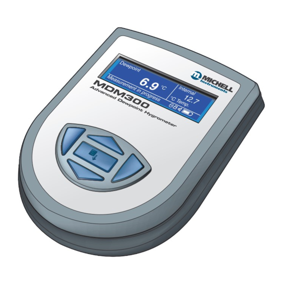
MDM300 User Manual INTRODUCTION INTRODUCTION The MDM300 Advanced Dew-Point Hygrometer is a portable instrument designed for on-line measurement of moisture content in non-corrosive gases over an operational range of -100 to +20 °C (-148...+68 °F). The instrument is contained within a steel fiber-loaded high-impact polyamide 6 case, sealed to IP66 / NEMA4 standard and is powered by an internally mounted Nickel Metal Hydride (NiMH) battery, designed to typically provide 48 hours continuous use between charges. -
Page 10: Figure 1 Mdm300 Advanced Dew-Point Hygrometer
MDM300 User Manual INTRODUCTION Two versions of the instrument are available, an MDM300 (standard) version and an MDM300 (intrinsically safe) version. This manual covers the MDM300 version only. For information about the MDM300 I.S. contact your local Michell Instruments’ representative (contact information at www.michell.com). -
Page 11: Controls And Indicators
MDM300 User Manual INTRODUCTION Controls and Indicators The controls and indicators associated with the MDM300 instrument are located on the front panel of the instrument. Connections to the MDM300 dew-point hygrometer, comprising the gas ports, battery charger input connector and input connector for the external sensor are all made to the top panel. -
Page 12: Table 1 Controls And Indicators
MDM300 User Manual INTRODUCTION Item Panel Description Function keys. Refer to Section 1.2 for the details of these Front keys. Instrument display, partitioned to show 3 main panels: The primary display shows internal sensor parameters. The secondary display indicates the external sensor Front parameter. -
Page 13: Function Keys
MDM300 User Manual INTRODUCTION Function Keys The function keys, located on the front panel, are used to select operations from the menus and to select and enter parameter variables within those menu levels. The function key described is shaded darker and the operation of the keys is as follows: 1.2.1 Enter Key Enter... -
Page 14: Instrument Display
MDM300 User Manual INTRODUCTION Instrument Display The graphics display and the associated function keypad ( Figure 2), form the operator interface of the equipment. Figure 3 shows all the elements of a typical display page after the instrument’s initialization period has completed. Table 2 details the elements of the display: Dewpoint Internal... -
Page 15: Display Units
MDM300 User Manual INTRODUCTION 1.3.1 Display Units The instrument can display the measured reading in the following units: Absolute Humidity • Moisture Content • • (AIR, USER, SF , CO or N Dew point • °C • °F • Relative Humidity (%) Mixing Ratio •... -
Page 16: Status Display Indications
MDM300 User Manual INTRODUCTION 1.3.2 Status Display Indications Initializing Internal Sensor’ ‘ This is displayed immediately after the instrument has been powered up, and indicates that the sensor is being heated up to accelerate equilibrium with the moisture in the sample gas. -
Page 17: Installation
MDM300 User Manual INSTALLATION INSTALLATION Safety It is essential that the installation of the electrical and gas supplies to this instrument be undertaken by qualified personnel. Unpacking the Instrument The MDM300 instrument is packed into a standard box and the method of unpacking is shown below: Figure 4 Packing Method... -
Page 18: Mdm300 Accessories
MDM300 User Manual INSTALLATION MDM300 Accessories The accessories for the MDM300 are shown in Figure 6 . Items 1...6 are supplied as standard and item 6 is optional. Please check that all the standard components are present after unpacking. Report any shortages immediately. Calibration certificate Charger unit Country-specific mains lead... -
Page 19: Figure 6 Accessories
MDM300 User Manual INSTALLATION Figure 6 Accessories Michell Instruments... -
Page 20: Operational Requirements
MDM300 User Manual INSTALLATION Operational Requirements Operational requirements are as follows: Sample gas flow rate: 0.2...1.2 Nl/min (0.5...2.5 scfh) Operating pressure: 0...350 barg (0...5075 psig) 2.4.1 Environmental Requirements – MDM300 Instrument Operating temperature range: -20...+50 °C (-4...+122 °F) Humidity: 0...100 % rh (non-condensing) Altitude: Up to 2000 m (6562 ft) 2.4.2... -
Page 21: Gas Inlet /Outlet Fittings
MDM300 User Manual INSTALLATION 2.5.1 Gas Inlet /Outlet Fittings HIGH PRESSURE! High pressure gases are potentially hazardous. Energy stored in these gases can be released suddenly and with extreme force. High pressure systems should be assembled and operated only by people who have been trained in proper safety practices. -
Page 22: Connect External Transmitters
MDM300 User Manual INSTALLATION Connect External Transmitters Dew point, pressure and temperature sensors and connecting cable can be ordered from Michell Instruments or a local representative. The connector and cable can be ordered separately to allow connection to any 4...20 mA loop powered sensor. External transmitters are plug-in devices and Figure 9 shows the method of connection. -
Page 23: Set-Up External Temperature Transmitter Parameters
MDM300 User Manual INSTALLATION 2.6.2 Set-Up External Temperature Transmitter Parameters After adding a temperature transmitter, the following parameters must be defined. Switch on the instrument and initially set the required DP/TEMP units to either °C, °F or K from the Settings Menu (refer to Section 3.4.1). EXTERNAL Using the option from the SET-UP Menu, set-up the instrument for an... -
Page 24: Entering User Pressure
MDM300 User Manual INSTALLATION 2.6.4 Entering User Pressure The MDM300 can be programmed with a pressure to be used in the calculation of atmospheric equivalent or pressure dew point, moisture content or absolute humidity. NOTE: Care should be taken to ensure that the entered pressure is correct as it may have a considerable effect on the measurement. -
Page 25: Battery Charging
MDM300 User Manual INSTALLATION Battery Charging The MDM300 is powered from an internally mounted, rechargeable Nickel Metal Hydride (NiMH) battery. Typically, depending upon the instrument settings, the battery will typically provide up to 48 hours of continuous operation when fully charged. A graphical display of battery charge state is provided and an audible warning is given as the battery approaches full discharge. - Page 26 MDM300 User Manual INSTALLATION The battery charger supplied is a ‘Smart’ charger. WARNING: DO NOT use any other charger than that supplied with this product. The use of any charger other than that supplied for use will invalidate the product warranty. The smart charger goes through three charging stages: •...
-
Page 27: Operation
MDM300 User Manual OPERATION OPERATION High pressure gases are potentially hazardous. Energy stored in these gases can be released suddenly and with extreme force. High pressure systems should be assembled and operated only by people who have been trained in proper safety practices. -
Page 28: Instrument Start-Up
MDM300 User Manual OPERATION Instrument Start-Up At switch on, the instrument goes through an initialization process lasting several minutes. During MDM300 this time the internal sensor is heated to a maximum System Initializing of +70 °C (+158 °F). The heating process increases the mobility of water molecules and accelerates equilibrium with the passing sample gas. -
Page 29: Overall Menu Structure And Operation
MDM300 User Manual OPERATION Overall Menu Structure and Operation 3.3.1 SET-UP Menu All instrument settings are made from the SET-UP Menu which is accessible from the Enter Main Display by pressing the key. On the first occasion after switch-on the Passcode Entry page will be displayed. Enter the passcode 7316 as follows:... -
Page 30: Figure 16 Menu Structure
MDM300 User Manual OPERATION Scroll Unit Files Page to view Main Display (Primary, Chart page Secondary and Status (only if internal sensor LOGGING? Windows) available) Logs Page PASSCODE FOR SETUP (on start-up only) =7316 Scroll to Adjust Digit Chart Reset Page PASSCODE To toggle Scroll... -
Page 31: Set-Up Menu Parameters
MDM300 User Manual OPERATION SET-UP Menu Parameters Follow the instructions in Section 3.3.1 to select the required parameters. 3.4.1 SETTINGS PRIMARY DP AT ATMOS SETTINGS DP/TEMP UNIT °C PRESSURE UNIT Psig GAS TYPE MOL WEIGHT CHART INTERVAL Figure 17 SETTINGS Page PRIMARY DP AT ATMOS SETTINGS... -
Page 32: Logging
MDM300 User Manual OPERATION 3.4.2 LOGGING The LOGGING Set-Up Menu can be accessed by pressing the key three times from the Main Display. It can also be accessed through the SET-UP Menu. > FILE NAME LOGGING PARAMETER DEWP LOG INTERVAL START? STOPPED Figure 18 LOGGING Page... -
Page 33: Bluetooth
MDM300 User Manual OPERATION The size of any one log file is limited to 60kb. If the unit is left logging, and the file size exceeds 60kb, then the log file will finish automatically. To ensure that the log file you initiate collects all the data from your test, an appropriate sample time should be chosen. -
Page 34: 3.4.3.1 Bluetooth Pairing Procedure
MDM300 User Manual OPERATION 3.4.3.1 Bluetooth Pairing Procedure When the instrument is in Bluetooth mode, a pairing procedure needs to be carried out in order for the PC system to recognize the instrument. This procedure only needs to be carried out once for each instrument. A typical pairing procedure is outlined in Figure 19. The procedure is as follows: From the PC’s Bluetooth menu, search for devices in range. -
Page 35: External (Sensor Interface)
MDM300 User Manual OPERATION 3.4.4 EXTERNAL (Sensor Interface) For more information refer to Section 2.6. EXTERNAL TYPE NONE EXTERNAL EXTERNAL ZERO EXTERNAL SPAN USER PRESSURE Psig Figure 21 EXTERNAL SET-UP Page EXTERNAL TYPE NONE EXTERNAL EXTERNAL ZERO EXTERNAL SPAN USER PRESSURE Psig Parameter Description... -
Page 36: Clock
MDM300 User Manual OPERATION 3.4.5 CLOCK YEAR CLOCK MONTH HOUR Figure 22 CLOCK Page YEAR CLOCK MONTH HOUR Parameter Description Current year YEAR Available Input: Range: 00 to 99 YEAR CLOCK MONTH Current month MONTH HOUR Available Input: Range: 01 to 12 Current day Available Input: Range: 01 to 31 Current hour... -
Page 37: Hmi
MDM300 User Manual OPERATION 3.4.6 CONTRAST BRIGHTNESS KEY TONE BL TIMEOUT LANGUAGE PRIMARY DISP INTERN Figure 23 HMI Page CONTRAST BRIGHTNESS KEY TONE BL TIMEOUT LANGUAGE Parameter Description PRIMARY DISP INTERN Sets the contrast on the screen. CONTRAST 0 to 100 % Available Input: Range: in 5 % increments Sets the brightness of the screen. -
Page 38: Info
MDM300 User Manual OPERATION 3.4.7 INFO MDM300 Portable Hygrometer Firmware 36171 Ver 10.10 Sensor serial number B585-006 Sensor next cal due 26/03/09 Sensor hours used 371 hr www.michell.com Figure 24 INFO Page This page contains system information and no changes can be made. Information available: •... -
Page 39: Log Files Page
MDM300 User Manual OPERATION 3.4.9 LOG FILES Page If the instrument is not logging, pressing the key, while the chart is displayed, will show the FILES Page. This page provides a list of all the previously saved log files, together with an indication of the available memory capacity (see Figure 25) . -
Page 40: 3.4.11 Calibration
MDM300 User Manual OPERATION The display shows: Indicates a log number for each set of log points Value of primary display parameter Value of secondary display parameter Status column which reports the status of the instrument at each log point in hexadecimal code. The status codes are explained in Appendix B. -
Page 41: Default Parameters
MDM300 User Manual OPERATION Default Parameters Associated Section Parameter Default Value Reference SETTINGS PRIMARY DP AT ATMOS DP/TEMP UNIT °C Section 3.4.1, Figure 16 PRESS UNIT psig GAS TYPE MOL WEIGHT CHART INTERVAL 5 sec LOGGING FILE NAME Section 3.4.2, Figure 17 PARAMETER DEWP LOG INTERVAL... -
Page 42: Guide To Measurement And Sampling
MDM300 User Manual OPERATION Guide to Measurement and Sampling Operating the MDM300 is very straightforward, but sampling conditions can vary greatly from one application to another. To get the best possible response speed, the appropriate procedure should be followed. HIGH PRESSURE! High pressure gases are potentially hazardous. -
Page 43: Measuring At Atmospheric Or System Pressure
MDM300 User Manual OPERATION It is highly recommended that a filter is installed upstream of the MDM300. Refer to the Sample Conditioning section of the Sampling Hints found in Section 4.1. 3.6.1 Measuring at Atmospheric or System Pressure Without a metering valve The large and small orifice fittings can be used to restrict flow at pressures up to 10 barg (145 psig). -
Page 44: Measurement Guide
MDM300 User Manual OPERATION 3.6.2 Measurement Guide Follow procedure A and note the result. Turn the instrument off. If you wish to measure at sample pressure then use the Michell Humidity Calculator (http://www.michell.com/uk/downloads/humidity_calculator. msi) to convert this result back to the equivalent at your sample pressure. Using this converted result, and the table below, find the appropriate procedure to measure your sample. - Page 45 MDM300 User Manual OPERATION Standard Purge (Pressure Measurement) Connect the MDM300 to the sample gas stream. Adjust the flow rate, using the outlet flow control valve, to between 0.2 and 1.2 Nl/min (0.5...2.5 scfh). The inlet flow control valve should be fully open.
-
Page 46: Conditional Sensor Purge
MDM300 User Manual OPERATION 3.6.3 Conditional Sensor Purge In order to ensure consistently fast measurement response speeds after power Off/On, the sensor will not be automatically purged when the measured dew point is deemed to be sufficiently close to the previously measured dew point. Battery Management The battery will typically provide 48 hours of continuous operation from full charge. -
Page 47: Good Measurement Practice
MDM300 User Manual GOOD MEASUREMENT PRACTICE GOOD MEASUREMENT PRACTICE Ensuring reliable and accurate moisture measurements requires the correct sampling techniques, and a basic understanding of how water vapor behaves. This section aims to explain the common mistakes and how to avoid them. Sampling Materials –... -
Page 48: Sampling Hints
MDM300 User Manual GOOD MEASUREMENT PRACTICE Temperature and Pressure effects As the temperature or pressure of the environment fluctuates, water molecules are adsorbed and desorbed from the internal surfaces of the sample tubing, causing small fluctuations in the measured dew point. Adsorption is the adhesion of atoms, ions, or molecules from a gas, liquid, or dissolved solid to the surface of a material, creating a film. - Page 49 MDM300 User Manual GOOD MEASUREMENT PRACTICE • Accentuate adsorption and desorption effects on the gas passing through the sampling system. • Allow pockets of wet gas to remain undisturbed in a complex sampling system, which will then gradually be released into the sample flow. •...
- Page 50 MDM300 User Manual GOOD MEASUREMENT PRACTICE Flow Rates Theoretically flow rate has no direct effect on the measured moisture content, but in practice it can have unanticipated effects on response speed and accuracy. The optimal flow rate varies depending on the measurement technology, and can always be found in the instrument or sensor manual.
-
Page 51: Application Software
MDM300 User Manual APPLICATION SOFTWARE APPLICATION SOFTWARE The latest version of this application software is available for download from the Michell website – http://www.michell.com/uk/support/sware-downloads.htm. The following authorization code will be required during the installation process: MDM-300-7392 Once the software has been installed and run, the MDM300 can be linked to the PC by activating the Bluetooth on the MDM300 and then connecting with the application software (see Section 3.4.3 for details). -
Page 52: Calibration
MDM300 User Manual CALIBRATION CALIBRATION Traceability The calibration of this instrument is traceable to national standards. For this reason the instrument should only be calibrated in an accredited, e.g. UKAS or NIST (U.S.) standards laboratory. If these facilities do not exist it is recommended that the instrument be returned to the manufacturer, Michell Instruments Ltd., or one of the approved agents. -
Page 53: Calibration Method
MDM300 User Manual CALIBRATION Calibration Method WARNING: These procedures require the use of specialized test equipment and calibration adjustments should only be carried out by qualified personnel. If not correctly carried out, the instrument’s calibration can be lost. The calibration procedure for the instrument is as follows: Switch on the instrument. -
Page 54: Calibration Correction Method
MDM300 User Manual CALIBRATION Calibration Correction Method NOTE: Any logging procedure currently in operation must be cancelled before the calibration procedures can be entered. To enter the CALIBRATION Menu page, highlight CALIBRATION from the SET-UP Menu Enter by using the or keys and press the key. -
Page 55: Easidew Offset Adjustment
MDM300 User Manual CALIBRATION 6.3.1 Easidew Offset Adjustment If an external Easidew transmitter has been configured this calibration option may be used to apply a constant offset over its full range, i.e. the calibration curve of the external Easidew transmitter is shifted either up or down depending upon the polarity of the offset. -
Page 56: Easidew One Point Adjustment
MDM300 User Manual CALIBRATION 6.3.2 Easidew One Point Adjustment If an external Easidew transmitter has been configured this calibration option may be used to apply a measured offset to just one specific point on the calibration curve of the external transmitter, without affecting any other parts of the curve. The single point selected is moved either up or down depending upon the polarity of the measured offset. -
Page 57: Shipping
MDM300 User Manual SHIPPING SHIPPING For shipping purposes the instrument should be packed into its original carton which will provide the recommended degree of protection during transit. To prepare the instrument for shipping, proceed as follows: Switch the instrument off and remove any connections to the Gas In and Gas Out ports and any external sensors connected to it. - Page 58 MDM300 User Manual APPENDIX A Appendix A Technical Specifications 97122 Issue 16.2 June 2022...
-
Page 59: Appendix A Technical Specifications
MDM300 User Manual APPENDIX A Appendix A Technical Specifications Performance Measurement Technology Michell ceramic metal-oxide moisture sensor ±1 °C from -60...+20 °Cdp (-76...+68 °Fdp) Accuracy ±2 °C from -100...-60 °Cdp (-148...-76 °Fdp) ±0.2 °C (0.3 °F) temperature For Spot Checks -70...+20 °Cdp (-95...+68 °Fdp) Calibrated Measurement Range For Online Analysis... -
Page 60: Dimensions
MDM300 User Manual APPENDIX A Dimensions Figure 39 Dimensions 97122 Issue 16.2 June 2022... - Page 61 MDM300 User Manual APPENDIX B Appendix B Datalog Status Display Michell Instruments...
-
Page 62: Appendix B Datalog Status Display
MDM300 User Manual APPENDIX B Appendix B Datalog Status Display When the status of the current log file is displayed, see Figure 38 , the column in the current log file display represents the instrument’s status at the time that each log point is recorded. -
Page 63: Table 13 Status Register Flags
MDM300 User Manual APPENDIX B Table 13 shows the status flags associated with each bit of the status register. If a status flag is set high then the associated condition exists. If it is set low, then that condition does not exist. Status Register Message Details... - Page 64 MDM300 User Manual APPENDIX C Appendix C FCC Declaration 97122 Issue 16.2 June 2022...
-
Page 65: Appendix Cfcc Declaration
MDM300 User Manual APPENDIX C Appendix C FCC Declaration FCC Declaration of Conformity MDM300 Advanced Dewpoint Hygrometer. This Device complies with FCC Rules Part 15 Subpart B Unintentional Radiators Class B digital devices. Operation is subject to the following conditions: 1) This device may not cause harmful interference 2) This device must accept any interference received, including interference that may cause undesired operation. - Page 66 MDM300 User Manual APPENDIX D Appendix D Quality, Recycling & Warranty Information 97122 Issue 16.2 June 2022...
-
Page 67: Appendix D Quality, Recycling, Compliance & Warranty Information
MDM300 User Manual APPENDIX D Appendix D Quality, Recycling, Compliance & Warranty Information Michell Instruments is dedicated to complying to all relevant legislation and directives. Full information can be found on our website at: www.michell.com/compliance This page contains information on the following directives: •... - Page 68 MDM300 User Manual APPENDIX E Appendix E Return Document & Decontamination Declaration 97122 Issue 16.2 June 2022...
-
Page 69: Appendix E Return Document & Decontamination Declaration
MDM300 User Manual APPENDIX E Appendix E Return Document & Decontamination Declaration Decontamination Certificate IMPORTANT NOTE: Please complete this form prior to this instrument, or any components, leaving your site and being returned to us, or, where applicable, prior to any work being carried out by a Michell engineer at your site. - Page 70 www.ProcessSensing.com http://www.michell.com...
Need help?
Do you have a question about the MICHELL Instruments MDM300 and is the answer not in the manual?
Questions and answers