
Subscribe to Our Youtube Channel
Related Manuals for PST NTRON Microx OC-49


Summary of Contents for PST NTRON Microx OC-49
- Page 1 Carbon Monoxide Analyzer User Manual NT-UM-2110-EN-01 NT-UM-2110-EN-00 05/2024 ProcessSensing.com P/N: 08-425...
-
Page 2: Revision History
For contact information, visit ProcessSensing.com Ntron Gas Measurement Ltd. Is part of the Process Sensing Technologies Group plc (PST). This document is the property of Process Sensing Technologies and may not be copied or otherwise reproduced, communicated to third parties, nor stored in any Data Processing System without the express written authorization of Process Sensing Technologies. -
Page 3: Before Using Your Microx
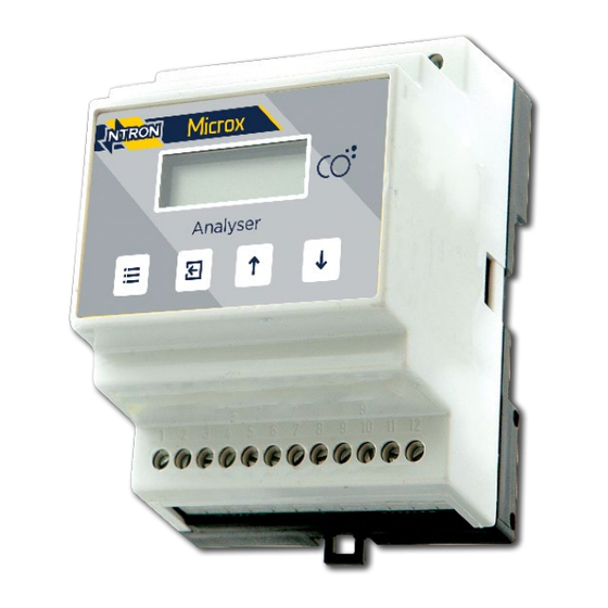
Microx Carbon Monoxide User Manual Before using your Microx This user manual applies to Microx DIN rail, panel and wall-mounted carbon monoxide (CO) analyzers with a serial number in this format: 2XXXXX, with version V.2.4.4 firmware. For Microx models with a different serial number format, please contact us at ie.ntron.sales@processsensing.com for user documentation. -
Page 4: Table Of Contents
Microx Carbon Monoxide User Manual Contents Revision History ....................i Before using your Microx................iii Safety information ..................iii Introduction ................... 6 1.1 Overview ....................6 Operation ..................6 Sensor Inputs.................7 Technical Specifications ..............8 Microx Module ..................9 Fuses ....................9 Mounting Options ................9 Field Connections .............. - Page 5 Microx Carbon Monoxide User Manual 4.2.6 Menu 6 – Sensor Selection..........18 4.2.7 Menu 7 ................... 18 4.2.8 Menu 8 - Diagnostics............18 4.2.9 Menu 9 – Restore..............19 4.2.10 Menu 10 – Zero Offset ............19 4.2.11 Menu 11 – PPM Sensor Gain..........19 4.2.12 Menu 12 –...
-
Page 6: Introduction
Microx Carbon Monoxide User Manual Introduction 1.1 Overview The Microx Module has been designed to allow Original Equipment Manufacturers (OEM) to use the module within their own equipment. This carbon monoxide analyzer is based on the common Microx module platform, hence the menu system is common throughout the Microx range. -
Page 7: Sensor Inputs
Microx Carbon Monoxide User Manual The sensor type is displayed The display then shows the gas level. The Microx CO analyser is now operational. 1.3 Sensor Inputs The Microx CO analyser uses a replaceable carbon monoxide sensor in a sample gas stream. -
Page 8: Technical Specifications
Microx Carbon Monoxide User Manual Technical Specifications Sensor Carbon Monoxide Model Number OC-49 Part Number 01-275 Measuring Range 0…50 ppm CO Output Resolution +/- 0.5 ppm CO Lower Detection Limit (LDL) 0.5 ppm CO Sample Flow Rate 150…250 ml/min (application dependent) Pressure Range (coefficient) Atmospheric +/- 10 % or 0.02 % mBar Response Time (T90) -
Page 9: Microx Module
Microx Carbon Monoxide User Manual Microx Module 3.1 Fuses A 500 mA anti-surge fuse is fitted to the OEM module, which is connected between the power supply and the OEM module. It is located next to the power input terminals. 3.2 Mounting Options DIN rail mounting version. -
Page 10: Field Connections
Microx Carbon Monoxide User Manual 3.3 Field Connections All connections to the module are provided in the form of screw terminals. The pin-outs for each Microx version are given below. (Terminals 22, 23, 24 are not used in all the following diagrams and no connection should be made to them.) 3.3.1 DIN rail mounting version... -
Page 11: Panel And Wall-Mount Versions - Dc Supply Option
Microx Carbon Monoxide User Manual 3.3.2 Panel and wall-mount versions – DC supply option (Terminals located at the rear of the module, identified as below as viewed.) View ‘A’ CO Sensor connections by Cable Colours 1 = No Connection 2 = Red 3 = Yellow 4 = White 5 = Black... -
Page 12: Panel And Wall-Mount Versions - Ac Supply Option
Microx Carbon Monoxide User Manual 3.3.3 Panel and wall-mount versions – AC supply option (Terminals located at the rear of the module, identified as below as viewed.) View ‘A’ CO Sensor connections by Cable Colours 1 = No Connection 2 = Red 3 = Yellow 4 = White 5 = Black... -
Page 13: Recommended Sampling System Piping
Microx Carbon Monoxide User Manual 3.4 Recommended Sampling System Piping Carbon monoxide Connecting pipework, 6 mm typically Exhaust gas Microx Analyser Flow-meter and control valve Set to 250 mLPM Regulator and gauge. Set to 5 psig Sample inlet gas 3.5 RS232 Connections Contact Ntron for details if required. -
Page 14: Software Features
Microx Carbon Monoxide User Manual Software Features The menu system featured within the Microx module allows all calibration and configuration activities to be performed. NOTE: It is important that the Microx module is correctly configured for the sensor in use, prior to performing any feature available in the menu system. -
Page 15: Menu Options
Microx Carbon Monoxide User Manual 4.2 Menu options Menu option Function Calibrate Sensor Analog output FSD Set 4 mA Set 20 mA Sensor simulation Not Applicable-DO NOT USE Not Applicable -DO NOT USE Diagnostics Not Applicable -DO NOT USE E:10 Not Applicable -DO NOT USE E:11 Not Applicable -DO NOT USE... -
Page 16: Menu 1 - Calibrate Sensor
Microx Carbon Monoxide User Manual 4.2.1 Menu 1 – Calibrate Sensor Press the MENU button to open the menu system. Using the NEXT and PREVIOUS buttons select menu option: E:1 Press ENTER. Apply a known concentration of gas (applicable to sensor type) at a flow-rate of between 100 to 500 ml/m. -
Page 17: Menu 2 - Analog Output Fsd
Microx Carbon Monoxide User Manual 4.2.2 Menu 2 – Analog Output FSD Press the MENU button to open the menu system. Using the NEXT and PREVIOUS buttons select menu option: E:2 Press ENTER. Using the INCREASE and DECREASE buttons adjust the FSD to the required level. -
Page 18: Menu 5 - Analog Output Simulation
Microx Carbon Monoxide User Manual Press ENTER. Press the MENU button to close the menu system. NOTE: The 20 mA factor will be displayed on exit 4.2.5 Menu 5 – Analog Output Simulation The Microx analog output can be tested for functionality via menu 5. This option allows the user to simulate the analog output. -
Page 19: Menu 9 - Restore
Microx Carbon Monoxide User Manual Using the NEXT and PREVIOUS buttons select menu option: E:8 Press ENTER. The display will alternate between the current value and diagnostic code E:8x: where x is: Sensor signal, A to D counts low ppm range. Sensor signal, A to D counts high ppm range. -
Page 20: Menu 14 - New Sensor Data
Microx Carbon Monoxide User Manual 4.2.14 Menu 14 – New Sensor Data This option allows the initial sensor calibration data to be set. It is used to predict the remaining sensor life. Press MENU to open the menu system. Using the NEXT and PREVIOUS buttons, select menu option: E:14 Press ENTER. - Page 21 Microx Carbon Monoxide User Manual Relay 2 is associated with alarm level 2. The user can select if the relay is normally Energized, E’ or normally de- energised, ‘d’ when the unit is not in an alarm condition. The relay can also be set to act on rising, ‘r’...
-
Page 22: Menu 18 - Alarm Levels
Microx Carbon Monoxide User Manual 4.2.18 Menu 18 – Alarm Levels This option allows the user to set the operation of the alarm levels. There are two alarms levels associated with two user configurable relays. Alarm level 1 is associated with relay 1. Alarm level 2 is associated with relay 2. -
Page 23: Routine Maintenance & Servicing
Microx Carbon Monoxide User Manual Routine Maintenance & Servicing The Microx analyser will provide reliable and fault-free service when given regular maintenance and calibrations. 5.1 Inspection and Maintenance It is advisable to periodically inspect the Microx analyser: Clean gas detector head using a clean DAMP cloth. ... - Page 24 Microx Carbon Monoxide User Manual Unplug the sensor from the PCB that sits in the top half of the sensor housing. Note the position of the sensor and the contact pins during removal of Top housing Sensor Flow-through housing the Sensor. Try and support the PCB when removing the sensor to prevent putting strain on the wiring connected to the PCB.
- Page 25 ProcessSensing.com Ntron Gas Measurement Ltd. Is part of the Process Sensing Technologies Group plc. © 2024 Process Sensing Technologies Ntron Ltd. Mullaghboy Industrial Park, Navan, Co. Meath, Ireland...
Need help?
Do you have a question about the NTRON Microx OC-49 and is the answer not in the manual?
Questions and answers