Table of Contents
Advertisement
Quick Links
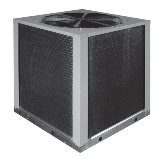
T6BQ- 090 (7.5 Ton) & 120 (10 Ton) Series
INSTALLATION INSTRUCTIONS
Split System Heat Pump - 2-Stage, 3-Phase, R-410A
It is your responsibility to know this product better than your customer. This includes being
able to install the product according to strict safety guidelines and instructing the customer on
how to operate and maintain the equipment for the life of the product. Safety should always be
the deciding factor when installing this product and using common sense plays an important
role as well. Pay attention to all safety warnings and any other special notes highlighted in the
manual. Improper installation of the furnace or failure to follow safety warnings could result in
serious injury, death, or property damage.
These instructions are primarily intended to assist qualified individuals experienced in the proper
installation of this appliance. Some local codes require licensed installation/service personnel
for this type of equipment. Please read all instructions carefully before starting the installation.
Return these instructions to the customer's package for future reference.
DO NOT DESTROY. PLEASE READ CAREFULLY & KEEP IN A SAFE PLACE FOR FUTURE REFERENCE.
IMPORTANT
ATTENTION INSTALLERS:
11.0 EER / 12.7 IEER
Advertisement
Table of Contents

Related Manuals for Nortek T6BQ-090 Series


Summary of Contents for Nortek T6BQ-090 Series
- Page 1 T6BQ- 090 (7.5 Ton) & 120 (10 Ton) Series 11.0 EER / 12.7 IEER INSTALLATION INSTRUCTIONS Split System Heat Pump - 2-Stage, 3-Phase, R-410A IMPORTANT ATTENTION INSTALLERS: It is your responsibility to know this product better than your customer. This includes being able to install the product according to strict safety guidelines and instructing the customer on how to operate and maintain the equipment for the life of the product.
-
Page 2: Table Of Contents
TABLE OF CONTENTS IMPORTANT SAFETY INFORMATION ......3 HEAT PUMP INSTALLATION ........4 General Information ............4 Before You Install the Heat Pump .........4 Locating the Heat Pump ..........4 Packaging Removal ............4 Rigging & Hoisting ............4 Rooftop .................4 Ground Level ..............5 Connecting Refrigerant Tubing Between the Indoor &... -
Page 3: Important Safety Information
IMPORTANT SAFETY INFORMATION WARNING: Please read all instructions before servicing this equipment. Pay attention to all safety warnings and any other special The information listed below must be followed notes highlighted in the manual. Safety markings are used during the installation, service, and operation frequently throughout this manual to designate a degree or of this unit. -
Page 4: Heat Pump Installation
HEAT PUMP INSTALLATION √ All units are securely packed at the time of shipment and upon arrival should be carefully inspected for damage prior General Information to installing the equipment at the job site. Verify coil fins The T6BQ series heat pump is designed only for outdoor are straight. -
Page 5: Ground Level
Ground Level ELECTRICAL WIRING Ground level installations must be located according to local building codes or ordinances and these requirements: WARNING: • Clearances must be in accordance with those shown in Figure 1 (page 4). To avoid risk of electrical shock, personal •... -
Page 6: Unbalanced 3-Phase Supply Voltage
Thermostat Connections • Use only copper wire for the line voltage power supply to this unit. Use proper code agency listed conduit and a • Thermostat connections should be made in accordance conduit connector for connecting the supply wires to the with the instructions supplied with the thermostat and the unit. -
Page 7: Defrost Control Board
TWO STAGE HEAT PUMP THERMOSTAT NOTE: C &W2 can be connected to optional electric heat. FIELD FIELD SUPPLIED SUPPLIED AIR HANDLER WIRING WIRING SECTION FREEZESTAT OUTDOOR BROWN SECTION See Note BLACK TERMINAL BOARD Figure 2. Typical Two Stage Heat Pump Thermostat Connection WIRE RECOMMENDED MAXIMUM WIRE LENGTH (FT) GAUGE... -
Page 8: Start Up & Adjustments
START UP & ADJUSTMENTS Heat Pump Cooling Operation (2-Stage) 1. Set the thermostat’s system mode to COOL and the fan Pre-Start Check List mode to AUTO. Gradually lower the thermostat temperature √ Verify the unit is level and allows condensate to drain. setpoint below room temperature and verify the outdoor √... -
Page 9: Heat Pump Maintenance
HEAT PUMP MAINTENANCE COMPONENT FUNCTIONS Defrost Control Board - This control includes - 5 minute WARNING: anti-short cycle timer protection for Stage 1 Heat/Cool, defrost time interval selection, and reversing valve, outdoor fan, and auxiliary heat operation during defrost control. See page 8. To prevent electrical shock, personal injury, or death, disconnect all electrical power to the unit Defrost Temperature Sensor - The switch can be located on... -
Page 10: Refrigerant Charging
REFRIGERANT CHARGING • If the pressure measured in Step 1 is greater than the required liquid refrigerant pressure determined in Step 3, then there is too much charge in the system. WARNING: Remove refrigerant and repeat Steps 1 through 3 until the system is correctly charged. - Page 11 T6BQ-090 Charging Chart - Cooling 7.5 Ton Split System Heat Pump w/ B6TM-090* Indoor Air Handler Remove refrigerant when above curve HIGH SPEED Stage 1 and 2 Operating Add refrigerant when below curve Liquid Temperature (° F) Figure 3. Charging Chart for 7.5 Ton Units T6BQ-120 Charging Chart - Cooling 10 Ton Split System Heat Pump w/ B6TM-120* Indoor Air Handler Remove refrigerant when above curve...
-
Page 12: Heat Mode Verification Charts And Application Notes (Heating Only)
Heat Mode Verification Charts and Application Notes (Heating Only) • Read all notes and warnings for the Cooling-mode charging charts prior to using these Heating-mode charge verification charts. Always use safe and environmentally sound methods when handling refrigerant handling or servicing the unit. Review the factory literature and safety warnings prior to servicing. •... - Page 13 T6BQ - 090 Heat Mode Verification Chart ˚ ID Rtn ˚ ID Rtn 62˚ OD Amb ˚ ID Rtn 47˚ OD Amb 17˚ OD Amb Liquid Temperature (° F) Figure 5. Verification Chart for 7 1/2 ton units T6BQ - 120 Heat Mode Verification Chart ˚...
-
Page 14: Figures & Tables
FIGURES & TABLES DO NOT OBSTRUCT TOP OF UNIT Allow 6' Minimum Clearance Figure 7. T6BQ Heat Pump Dimensions Model Unit Weights (Lbs.) Height -H- Width -W- Depth -D- Shipping Height Number Without Packaging Shipping Weight All dimensions in inches T6BQ- 090C 44 1/4... -
Page 15: Electrical Information
Electrical Information 090C 090D 120C 120D Model Number 208-230V 460V 208-230V 460V T6BQ- 1012987 1012989 1012988 1012990 PERFORMANCE DATA Gross Cooling Capacity (95 F) Btuh 92,400 92,400 121,200 121,200 Net Cooling Capacity - Btuh 90,000 90,000 116,500 116,500 A.H.R.I. Rated Airflow - C.F.M. 3,000 3,000 4,000... - Page 16 Figure 8. T6BQ Wiring Diagram...
-
Page 20: Installation Check List
MOTORS Blower Motor Fan Motor COMPONENTS Blower Assembly Fan Grille Cabinet Panels Filter/Driers Expansion Valves Specifications & illustrations subject to change without notice or incurring obligations (01/18). 10131290 O’Fallon, MO, © Nortek Global HVAC LLC 2018. All Rights Reserved. (NEW)
Need help?
Do you have a question about the T6BQ-090 Series and is the answer not in the manual?
Questions and answers