Table of Contents
Advertisement
Quick Links
P6SP - 072 / 090 / 120 Series, A Revision
INSTALLATION INSTRUCTIONS
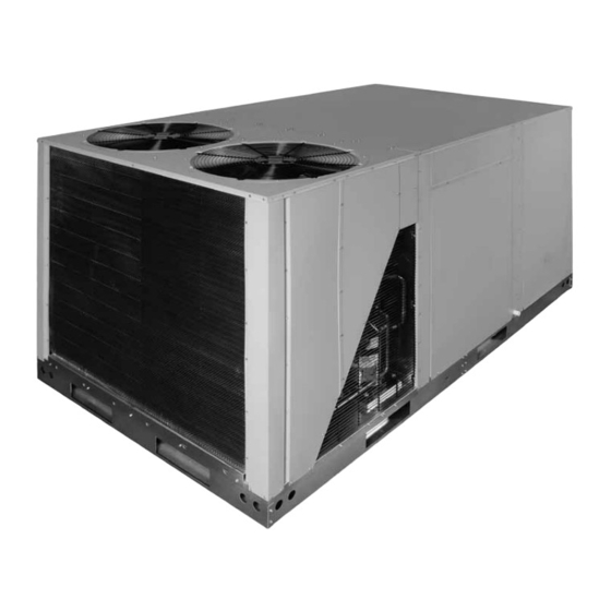
Single Package Electric Heating / Electric Cooling Rooftop Unit
10T Unit Shown
IMPORTANT
ATTENTION INSTALLERS:
It is your responsibility to know this product better than your customer. This includes being
able to install the product according to strict safety guidelines and instructing the customer on
how to operate and maintain the equipment for the life of the product. Safety should always be
the deciding factor when installing this product and using common sense plays an important
role as well. Pay attention to all safety warnings and any other special notes highlighted in the
manual. Improper installation of the furnace or failure to follow safety warnings could result
in serious injury, death, or property damage.
These instructions are primarily intended to assist qualified individuals experienced in the
proper installation of this appliance. Some local codes require licensed installation/service
personnel for this type of equipment. Please read all instructions carefully before starting the
installation. Return these instructions to the customer's package for future reference.
DO NOT DESTROY. PLEASE READ CAREFULLY AND KEEP IN A SAFE PLACE FOR FUTURE REFERENCE.
Advertisement
Table of Contents

Related Manuals for Nortek P6SP-072 Series


Summary of Contents for Nortek P6SP-072 Series
- Page 1 P6SP - 072 / 090 / 120 Series, A Revision INSTALLATION INSTRUCTIONS Single Package Electric Heating / Electric Cooling Rooftop Unit 10T Unit Shown IMPORTANT ATTENTION INSTALLERS: It is your responsibility to know this product better than your customer. This includes being able to install the product according to strict safety guidelines and instructing the customer on how to operate and maintain the equipment for the life of the product.
-
Page 2: Table Of Contents
TABLE OF CONTENTS SAFETY INFORMATION ..........2 FIGURES & TABLES ..........12 Figure 9 - P6SP Components ......12 GENERAL INFORMATION ..........3 Physical Data ............13 Equipment Check ............3 Figure 10 - P6SP - 072 Series ......13 Unit Location .............3 Figure 11 - P6SP - 090 Series ......15 Clearances to Combustible Materials ......3 Figure 12 - P6SP - 120 Series ......17 Thermostat ..............4... -
Page 3: General Information
• Follow all precautions in the literature, on tags, and WARNING: on labels provided with the equipment. Read and thoroughly understand the instructions provided with Do not place combustible material on or against the equipment prior to performing the installation and the unit cabinet. -
Page 4: Thermostat
Recommended Clearances for Servicibility 60" Minimum Required Clearances to Combustibles 36" 48" 36" 3" 36" Min. Condensate Roof Curb 36" Drain 48" Figure 2. Condensate Drain UNIT INSTALLATION Figure 1. Minimum Clearances to Minimum Clearance Requirements Combustibles Units are certified as combination Heating and Cooling equipment for outdoor installation only at the minimum The electric unit is suitable for installation on combustible clearances to combustible materials shown. -
Page 5: Rooftop Mounting
Units may be installed on wood flooring or on Class A, B, Wood Cap or C roof covering material when used with side supply Assembly and return air ducts. (Horizontal Discharge Kit required.) Units may be installed on wood flooring or on Class A, B, or C roof covering material when used with bottom discharge and return air ducts in conjunction with a roof Top Crate... -
Page 6: Circulating Air Supply
CIRCULATING AIR SUPPLY must be square and level to ensure proper condensate drainage. Unit clearances must be in accordance with WARNING: those shown in Figure 1 (page 4). Unconditioned Spaces Do not allow combustion products to enter the All ductwork passing through unconditioned spaces return air ductwork or the circulating air supply. -
Page 7: Unconditioned Spaces
Unconditioned Spaces Line Voltage All ductwork passing through unconditioned space must be It is recommended that the line voltage to the unit be properly insulated to prevent condensation and minimize supplied from a dedicated branch circuit containing the duct losses. Use insulation with an outer vapor barrier. correct fuse or circuit breaker for the unit. -
Page 8: Grounding
1. Measure the line voltages unit. Use proper code agency listed conduit and a conduit Example of your 3-phase power connector for connecting the supply wires to the unit and supply where it enters the for obtaining proper grounding. Grounding may also be building and at a location accomplished by using the grounding lug provided in the AB = 451V... -
Page 9: Blower Speed
Blower Speed Start-Up Procedure The blower speed is preset at the factory for an external static pressure of 0.2-0.3 in-Wg. For optimum system WARNING: performance and comfort, it may be necessary to change the factory set speed. Refer to Blower Performance Data The unit is equipped with crankcase heaters. -
Page 10: Verifying Operation Of Over-Temperature Limit Control
1. Set the thermostat to above room temperature. 2. Electrical power to the unit is turned on. 2. Verify that the compressor and outdoor fan motor are 3. All safety switches are closed. not energized and the electric heat is energized. 4. -
Page 11: Routine Maintenance
REPLACEMENT PARTS Routine Maintenance Proper maintenance is important to achieve optimum Replacement parts are available through all NORDYNE performance from the air conditioner. The ability to properly distributors. When ordering, remember to have the perform maintenance on this equipment requires certain complete Model and Serial number of the unit. -
Page 12: Figures & Tables
FIGURES & TABLES Figure 9. P6SP Components... -
Page 13: Physical Data
PHYSICAL DATA Dimensions shown in inches (mm) Corner D Corner A 16 1/2 (419) 30 1/2 30 1/2 (775) (775) 16 1/2 TOP VieW (419) Corner C Corner B 101 1/2 1 1/4 (2578) (31.8) Control Access Heater Element Access &... - Page 14 PHYSICAL DATA - continued Dimensions shown in inches (mm) 15 3/8 CONDENSER END Optional Economizer Hoods Recommended unit Rating disconnect mounting Label location (127) HEAT EXCHANGER END 1 3/4 (44) (228) 42 3/4 (1085) 3 1/2 (228) (88) External Power Entry (102) 7 (178) 7 (178)
- Page 15 PHYSICAL DATA - continued Dimensions shown in inches (mm) Corner D Corner A TOP VieW Corner C Corner B 101 1/2 (406) (2578) Optional Field Wiring Control Access Hail Guard (†)Electric Element Hood Access Blower Access FrOnT VieW Condesate Drain 4 (102) 2 (51) 30 3/4...
- Page 16 PHYSICAL DATA - continued Dimensions shown in inches (mm) Rating Label Recommended Unit Disconnect Mounting Location HEAT EXCHANGER END 4 (102) Airflow Airflow Compressors (x2) CONDENSER END 7 (178) 7 (178) Return Air Opening 5-3/4 (146) 16 1/2 16 1/2 (419) (419) 30 1/2...
- Page 17 PHYSICAL DATA - continued Dimensions shown in inches (mm) Corner “A” Corner “D” Condenser Filters (4) Evaporator TOP VieW Condenser Blower Assembly Corner “B” Corner “C” 101-1/2 (2578) (406) Recommended Unit Disconnect Location Optional Control Access † Field Wiring Hail Guard (Electric Element Hood Access)
- Page 18 PHYSICAL DATA - continued Dimensions shown in inches (mm) 57 1/2 (1461) Airflow Airflow 18 1/2 (470) Optional Fresh Air Condenser Coil Intake Hood Compressors (2) 5 (127) 1 3/4 (44) Optional Relief Hood 4 1/4 (108) 4 3/4 (121) 8 (203) 4 1/4 (102) Electrical Supply Entries...
-
Page 19: Electrical Information
ELECTRICAL INFORMATION Model Number Nominal Unit Outdoor Total High Static Indoor Motor Unit Only P6SP- Voltage Compressors Motors Unit (See Note 4) Circuit (See Notes 2 & 3) (See Note 1) (2) ea. Factory Unit Electrical Data: -072C 208 - 230 V 1 ea. - Page 20 Model Single Circuit (Unit + Heater Kit) See Note Nominal Unit High Static Number Voltage Kit # P6SP- Factory Unit Electrical Data: 9 kW 18 kW 30 kW 35 kW 9 kW 18 kW 30 kW 35 kW -072C 208 - 230 V 30 - 31 50 - 57 80 - 91...
- Page 21 Figure 13. Wiring Diagram for P6SP-072/090/120 (C/D) Series...
- Page 22 CCH2 CCH1 Figure 14. Ladder Diagram for P6SP-072/090/120 (C/D) Series...
-
Page 23: Blower Performance Tables
Blower Performance Tables This equipment is outfitted with a belt driven blower assembly in order to accommodate a large variety of duct configurations and airflow selections. The blower has been factory inspected for proper alignment, operation and rotational direction prior to the drive motor being situated in the shipping position. The blower drive belt is located with these instructions and must be installed by the service technician. - Page 24 P6SP-072(C/D) Factory Standard: 1Hp Down-flow Performance Chart ‡ Indicates Factory Sheave Setting Adjustable Motor Sheave Setting External Operating Unit @ 230 or Fully Static Turns Turns Turns Turn Turn Turns Turns Turns Turns Turns Turns Turns 460 Volts Closed (in-Wg) Open Open Open ‡...
- Page 25 P6SP-072(C/D) Factory Standard: 1.5Hp Horizontal Performance Chart ‡ Indicates Factory Sheave Setting for Pre-configured Units Adjustable Motor Sheave Setting External Operating Unit @ 230 or Fully Static Turns Turn Turn Turns Turns Turns Turns Turns Turns Turns Turns Turns 460 Volts Closed (in-Wg) Open...
- Page 26 P6SP-090(C/D)a Factory Standard: 1.5Hp Downflow Performance Chart ‡ Indicates Factory Sheave Setting Adjustable Motor Sheave Setting External Operating Unit @ 230 or Fully Static Turns Turns Turns Turn Turn Turns Turns Turns Turns Turns Turns Turns 460 Volts Closed (in-Wg) Open Open Open...
- Page 27 P6SP-090(C/D)a Factory Standard: 1.5Hp Horizontal Performance Chart ‡ Indicates Factory Sheave Setting for Pre-configured Units Adjustable Motor Sheave Setting External Operating Unit @ 230 or Fully Static Turns Turns Turns Turn Turn Turns Turns Turns Turns Turns Turns Turns 460 Volts Closed (in-Wg) Open...
- Page 28 P6SP-120(C/D)a & Q6SP-120(C/D)a Factory Standard: 1.5Hp Down-flow Performance Chart ‡ Indicates Factory Sheave Setting Adjustable Motor Sheave Setting External Operating Unit @ 230 or Fully Static Turn Turn Turns Turns Turns Turns Turns Turns Turns Turns Turns Turns 460 Volts Closed (in-Wg) Open...
- Page 29 P6SP-120(C/D)a & Q6SP-120(C/D)a Factory Standard: 1.5Hp Horizontal Performance Chart ‡ Indicates Factory Sheave Setting for Pre-configured Units Adjustable Motor Sheave Setting External Operating Unit @ 230 or Fully Static Turns Turns Turns Turns Turns Turns Turn Turn Turns Turns Turns Turns 460 Volts Closed...
-
Page 30: P6Sp Charging Charts
P6SP CHARGING CHARTS, COOLING ONLY APPLICATION NOTES ON THE USE OF CHARGING CHARTS match the measured liquid temperature to the units chart. This equipments cooling systems contain refrigerant under The measured liquid pressure reading should be within high pressure, always use safe practices when servicing 3% of the value shown for most installations. - Page 31 P6SP CHARGING CHARTS (CONTINUED) Charging Chart - Cooling Operation - 7.5T P6 Packaged Units * See Application Notes for use Remove refrigerant when above curve Add refrigerant when below curve 50 55 60 65 70 75 80 85 90 95 100 105 110 115 120 125 130 135 Liquid Temperature (F) Figure 16.
-
Page 32: Installation Checklist
Date Installed: ______________________________________ Installation Type: Horizontal / Downflow inSTALLer: PLeASe LeAVe THeSe INSTRUCTIONS WITH THE OWNER. Specifications & illustrations subject to change without notice or incurring obligations (05/15). 709270A (Replaces 7092700) O’Fallon, MO, © Nortek Global HVAC LLC 2015. All Rights Reserved.
Need help?
Do you have a question about the P6SP-072 Series and is the answer not in the manual?
Questions and answers