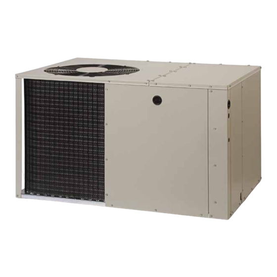
Nortek VP7RE Series Installation Instructions Manual
Single package air conditioner - single stage, r-410a
Hide thumbs
Also See for VP7RE Series:
- Installation instructions manual (20 pages) ,
- Installation instructions manual (16 pages) ,
- Installation instructions manual (20 pages)
Table of Contents
Advertisement
P7RE SERIES
INSTALLATION INSTRUCTIONS
SINGLE PACKAGE AIR CONDITIONER - SINGLE STAGE, R-410A
It is your responsibility to know this product better than your customer. This includes being
able to install the product according to strict safety guidelines and instructing the customer on
how to operate and maintain the equipment for the life of the product. Safety should always be
the deciding factor when installing this product and using common sense plays an important
role as well. Pay attention to all safety warnings and any other special notes highlighted in the
manual. Improper installation of the furnace or failure to follow safety warnings could result in
serious injury, death, or property damage.
These instructions are primarily intended to assist qualified individuals experienced in the proper
installation of this appliance. Some local codes require licensed installation/service personnel
for this type of equipment. Please read all instructions carefully before starting the installation.
Return these instructions to the customer's package for future reference.
DO NOT DESTROY. PLEASE READ CAREFULLY & KEEP IN A SAFE PLACE FOR FUTURE REFERENCE.
IMPORTANT
ATTENTION INSTALLERS:
14 SEER
Advertisement
Table of Contents

Summary of Contents for Nortek VP7RE Series
- Page 1 P7RE SERIES 14 SEER INSTALLATION INSTRUCTIONS SINGLE PACKAGE AIR CONDITIONER - SINGLE STAGE, R-410A IMPORTANT ATTENTION INSTALLERS: It is your responsibility to know this product better than your customer. This includes being able to install the product according to strict safety guidelines and instructing the customer on how to operate and maintain the equipment for the life of the product.
-
Page 2: Table Of Contents
TABLE OF CONTENTS IMPORTANT SAFETY INFORMATION Please read all instructions before servicing this equipment. Pay attention to all safety warnings and any other special IMPORTANT SAFETY INFORMATION ......2 notes highlighted in the manual. Safety markings are used frequently throughout this manual to designate a degree or GENERAL INFORMATION .......... -
Page 3: General Information
• Verify the required speed from the airflow data found in Table CAUTION: 3, (page 11). Place appropriate wire on the appropriate motor speed tap for the required airflow. This unit uses R-410A refrigerant. DO NOT use any other refrigerant in this unit. Use of another GENERAL INFORMATION refrigerant will damage the unit. -
Page 4: Minimum Clearance Requirements
Minimum Clearance Requirements • For highly resistive duct systems it may be necessary to add an additional return air duct and or supply to achieve maximum Sufficient clearance for unobstructed airflow through the outdoor performance and prevent coil icing and refrigerant flood back. coil must be maintained in order to provide room for proper •... -
Page 5: Air Conditioner Installation
AIR CONDITIONER INSTALLATION Unpacking the Unit It is recommended that the unit be unpacked at the installation site to minimize damage due to handling. CAUTION: Do not tip the unit on its side. Oil may enter the compressor and cause damage. 1. -
Page 6: Locating & Installing The Supply Damper(S)
Condensate Drainage Locating & Installing the Supply Damper(s) A 3/4” condensate fitting extends out of the side of the unit (Figure 6). The drain trap, shipped in the electrical compartment, CAUTION: must be installed to prevent water from collecting inside the unit. 1. -
Page 7: Grounding
be made in accordance with the instructions supplied with the thermostat and the indoor equipment. • The low voltage wires must be properly connected. Route 24V control wires through the sealing grommet near the power entrance. See Figure 7. Recommended wire gauge and wire lengths for typical thermostat connections are listed in Table •... -
Page 8: Blower Speed
Start-Up Procedure Blower Speed For optimum system performance and comfort, it may be CAUTION: necessary to change the factory speed setting. See Table 3, (page 11) for factory settings. If the unit is equipped with a crankcase heater, WARNING: allow 24 hours prior to continuing the start up procedures to allow for heating of the refrigerant To avoid electric shock, personal injury, or death, compressor crankcase. -
Page 9: Air Conditioner Maintenance
AIR CONDITIONER MAINTENANCE If the outdoor temperature is above 65 degrees F or higher: Charge the system following the steps below: 1. With the system operating at steady state, measure the WARNING: superheat at suction line service valve for fixed orifice systems, like P7RE-018K/024K/030K/036K/042K/ 048KA, or measure To prevent electrical shock, personal injury, or the subcooling at the liquid service valve for TXV systems,... -
Page 10: Figures & Tables
FIGURES & TABLES Top View “A” “B” 3” 5.5” Opening for Opening for 12" Diameter 12" Diameter Supply Duct Return Duct 9.15” 1" 3.15” 9” 17.50” Rear View (1.5, 2, 2.5, & 3 Ton) 1.75” Ø Electric Heater Power Supply 1.13”... - Page 11 HEAT RISE DATA (BASED ON NOMINAL 10KW ELECTRIC HEAT KIT) EXTERNAL STATIC PRESSURE DROP - INCHES WATER COLUMN BLOWER UNIT SETTING HEAT HEAT HEAT HEAT HEAT HEAT HEAT HEAT RISE RISE RISE RISE RISE RISE RISE RISE Tap T1 Tap T2* 018K Tap T3 Tap T4**...
-
Page 12: Wiring Diagrams
Wiring Diagrams Figure 10. Wiring Diagram (1.5, 2, & 2.5 Ton Models) - Page 13 Figure 11. Wiring Diagram (3, 3.5, 4, & 5 Ton Models)
-
Page 16: Installation Checklist
Fan Motor COMPONENTS: • Blower Assembly • Fan Grille • Cabinet Panels • Filter/Driers • Expansion Valves 10331190 Specifications & illustrations subject to change without notice or incurring obligations (05/21). (Replaces 1033141A) © Nortek Global HVAC LLC 2021. All Rights Reserved.


Need help?
Do you have a question about the VP7RE Series and is the answer not in the manual?
Questions and answers