Table of Contents
Advertisement
Quick Links
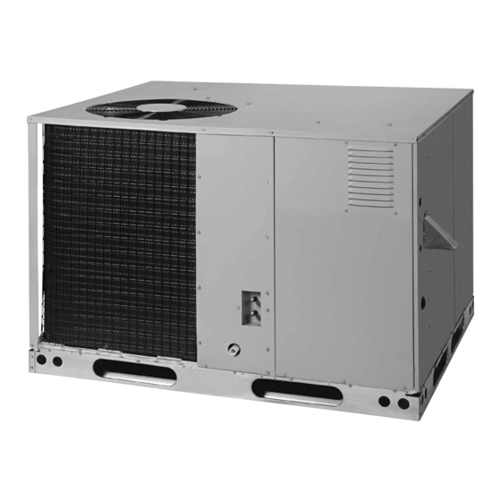
R6GF SERIES
USER'S MANUAL & INSTALLATION INSTRUCTIONS
Single Package Gas Heating / Electric Cooling
Premium Model Shown
FIRE OR EXPLOSION HAZARD
• Failure to follow safety warnings exactly
could result in serious injury or property
damage.
• Installation and service must be performed
by a qualified installer, service agency or the
gas supplier.
• Do not store or use gasoline or other
flammable vapors and liquids in the vicinity
of this or any other appliance.
DO NOT DESTROY. PLEASE READ CAREFULLY AND KEEP IN A SAFE PLACE FOR FUTURE REFERENCE.
It is your responsibility to know this product better than your customer. This includes being able to install the product according
to strict safety guidelines and instructing the customer on how to operate and maintain the equipment for the life of the product.
Safety should always be the deciding factor when installing this product and using common sense plays an important role as
well. Pay attention to all safety warnings and any other special notes highlighted in the manual. Improper installation of the unit
or failure to follow safety warnings could result in serious injury, death, or property damage. These instructions are primarily
intended to assist qualified individuals experienced in the proper installation of this appliance. Some local codes require
licensed installation/service personnel for this type of equipment. After completing the installation, return these instructions to
the customer's package for future reference.
!
WARNING:
• Do not try to light any appliance.
• Do not touch any electrical switch; do not
use any phone in your building.
• Leave the building immediately.
• Immediately call your gas supplier from a
neighbors phone. Follow the gas suppliers
instructions.
• If you cannot reach your gas supplier, call
the fire department.
ATTENTION INSTALLERS:
WHAT TO DO IF YOU SMELL GAS
15 SEER
Advertisement
Table of Contents
Troubleshooting

Related Manuals for Nortek R6GF Series


Summary of Contents for Nortek R6GF Series
- Page 1 R6GF SERIES 15 SEER USER’S MANUAL & INSTALLATION INSTRUCTIONS Single Package Gas Heating / Electric Cooling Premium Model Shown WARNING: FIRE OR EXPLOSION HAZARD WHAT TO DO IF YOU SMELL GAS • Failure to follow safety warnings exactly • Do not try to light any appliance.
- Page 2 USER INFORMATION Important Safety Information ........4 WARRANTY INFORMATION Operating Instructions ..........4 A warranty certificate with full details is included with the Cooling Operation .............4 Air Conditioner. Carefully review these responsibilities with Heating Operation .............4 your dealer or service company. The manufacturer will not Turning the Air Conditioner Off ........4 be responsible for any costs found necessary to correct Operating the Indoor Blower Continuously ....4...
-
Page 3: Table Of Contents
INSTALLER INFORMATION IMPORTANT SAFETY INFORMATION .......5 STARTUP & ADJUSTMENTS ........18 Pre - Start Checklist ..........18 REQUIREMENTS & CODES ........6 Start-up Procedure ..........18 GENERAL INFORMATION ..........7 Air Circulation ............18 Before You Install this Unit .........7 System Cooling ............19 Locating the Equipment..........7 System Heating ............19 Heating Load ............7 Verifying &... - Page 4 USER INFORMATION IMPORTANT SAFETY INFORMATION Turning the Unit OFF Change the thermostat’s system mode to OFF and the fan Safety markings are used frequently throughout this mode to AUTO (See Figure 1). NOTE: The system will not manual to designate a degree or level of seriousness and operate, regardless of the temperature selector setting.
-
Page 5: Important Safety Information
INSTALLER INFORMATION IMPORTANT SAFETY INFORMATION WARNING: Please read all instructions before servicing this equipment. Do not place combustible material on or against Pay attention to all safety warnings and any other special the unit cabinet. Do not place combustible notes highlighted in the manual. Safety markings are materials, including gasoline and any other used frequently throughout this manual to designate a flammable vapors and liquids, in the vicinity of... -
Page 6: Requirements & Codes
REQUIREMENTS & CODES • This equipment contains liquid and gaseous refrigerant under high pressure. Installation or servicing should only This unit must be installed in accordance with be performed by qualified trained personnel thoroughly instructions outlined in this manual, all applicable familiar with this type equipment. -
Page 7: General Information
GENERAL INFORMATION Where accessibility to clearances are greater than clearances to combustibles, accessibility The R6GF Single Package Gas Heating / Electric Cooling clearances must take preference. Unit is designed only for outdoor rooftop or ground level • The hot condenser air must be discharged up and away installations and can be readily connected to the duct from the home. -
Page 8: Venting Requirements
Air openings in the door of the unit, warm air registers, and The following list summarizes the requirements for the return air grilles must never be restricted. If the unit does location of the vent system termination: not receive an adequate supply of air for combustion, the •... - Page 9 AVERTISSEMENT: WARNING: RISQUE D’EMPOISONNEMENT AU CARBON MONOXIDE POISONING HAZARD MONOXYDE DE CARBONED Failure to follow the steps outlined below for each appliance connected to the venting Le non-respect des consignes suivantes portant sur chacun des appareils raccordés au système system being placed into operation could result d’évacuation mis en service pourrait entraîner in carbon monoxide poisoning or death.
-
Page 10: Circulating Air Supply
Circulating Air Supply • If outside air is utilized as return air to the unit for ventilation or to improve indoor air quality, the system WARNING: must be designed so that the return air to the unit is not less than 50° F (10° C) during heating operation. Products of combustion must not be allowed to •... -
Page 11: Acoustical Duct Work
Acoustical Duct Work • Sufficient clearance for unobstructed airflow through Certain installations may require the use of acoustical the outdoor coil must also be maintained in order to lining inside the supply duct work. achieve rated performance. See page 7 for information •... -
Page 12: Electrical Wiring
ELECTRICAL WIRING WARNING: To avoid risk of electrical shock, personal injury, or death,disconnect all electrical power to the unit before performing any maintenance or service. The unit may have more than one electrical supply. Label all wires prior to disconnection when servicing the unit. -
Page 13: Grounding
Voltage Range Compressor Single Circuit Maximum Nominal Indoor Model Heating Electrical Motor Blower Number Input Supply R6GF-X24K072C 72,000 208-230/30/1 11.4 52.0 0.91 20.8 30.0 R6GF-X36K100C 100,000 208-230/30/1 19.0 82.0 1.46 30.9 45.0 R6GF-X48K120C 120,000 208-230/30/1 24.0 96.0 1.46 41.9 60.0 R6GF-X60K120C 120,000 208-230/30/1... -
Page 14: Checking Heat Anticipator Settings
Configuring the Variable Speed Blower blower when only air circulation is desired. Connect the red, yellow, green and brown low voltage wires to the R or The variable speed blower has been designed to give RC, Y, G, and W terminals respectively on the thermostat the installer maximum flexibility for optimizing system base. -
Page 15: Selecting Gas Heating Airflow
Selecting Gas Heating Airflow If the constant 24 VAC (R wire) is not present in the outdoor The heating airflow is selected by setting switches 5 & unit, use one of the spare wires in the thermostat cable to 6. Refer to Table 11 (page 26) and select a nominal rise bring power to the module. -
Page 16: Dc Sol Connection
DC SOL Connection Installation Verification The two pin DC SOL connector provides a connection To verify the Comfort Alert is correctly installed, two to the Copeland UltraTech second stage compressor functional tests can be performed. solenoid (see Figure 14). This 24VDC solenoid is internal 1. -
Page 17: Gas Supply & Piping
GAS SUPPLY & PIPING After the gas piping to the unit is complete, all connections must be tested for gas leaks. This includes pipe connections • All gas piping must be installed in compliance with at the main gas valve, emergency shutoff valve and local codes and utility regulations. -
Page 18: Lp/Propane Gas Conversion
START UP & ADJUSTMENTS Shut-Off Valve with 1 /8 NPT Pre-Start Check List Automatic Gas Valve plugged tap (with manual shut-off) √ Verify the unit is level and allows proper condensate drainage. √ Verify all clearance requirements are met and there is Some utilities require Shut-Off free airflow to and from the outdoor coil. -
Page 19: System Cooling
System Cooling The VSB is designed with built in delay profiles for start 1. Set the thermostat’s system mode to COOL and the up and shut down of the system. Refer to the Operating fan mode to AUTO. Gradually lower the thermostat Sequence section (page 21) for more details. -
Page 20: Verifying Burner Operation
Verifying Burner Operation Manifold Pressure Adjustment The manifold pressure must be set to the appropriate WARNING: value for your installation. To adjust the manifold pressure: 1. Obtain the required manifold pressure setting. Use Uninsulated live components are exposed when Table 5 for natural gas or Table 6 for LP/propane gas. louvered control access panel is removed. -
Page 21: Operating Sequence
OPERATING SEQUENCE 8. The furnace control energizes the circulating air blower at a very low speed. After 30 seconds, the blower will The operating sequences for the heating, cooling, and fan ramp to the airflow selected for heating. modes are described below. Refer to the field and furnace 9. -
Page 22: Equipment Maintenance
EQUIPMENT MAINTENANCE • The motors for the circulating air blower, outdoor fan, and combustion blower are pre-lubricated at the factory. WARNING: No further oiling is required for the life of this product. • Inspect and clean the screen of the vent cover assembly To avoid risk of electrical shock, personal injury, at the beginning of each heating and cooling season. -
Page 23: Cleaning Of Burners
COMPONENT FUNCTIONS into the top portion of the heat exchanger. Operate the drill alternating between forward and reverse, working Comfort Alert™ Diagnostics the cable in and out several times to obtain sufficient The Comfort Alert diagnostics module troubleshoots cleaning. Repeat this process at each exchanger tube. heat pump and air conditioning system failures and 13. -
Page 24: Troubleshooting
REPLACEMENT PARTS TROUBLESHOOTING Replacement parts are available through your distributor. If the unit does not operate in the cooling mode, check Please have the complete model and serial number of the following: the unit when ordering replacement parts. • The thermostat is operating properly ELECTRICAL: •... -
Page 25: Figures & Tables
FIGURES & TABLES 3/4" NPT Female 24 9/10 Drain Connector DOWNFLOW SUPPLY DUCT OPENING 47 1/2 13 1/2 13 1/2 13 3/10 DOWNFLOW 23 1/2 RETURN DUCT OPENING Electric Top View Supply Entry Low Voltage Entry Gas Supply 29.75 Entry 23.75 15.75 47.5... -
Page 26: Airflow Information
AIRFLOW INFORMATION Model Number Heating Input Heating Output Heat Switch Heating Rise Cooling Output Blower Motor R6GF- (Btuh) (Btuh) Setting Range (°F) (Btuh) Size (HP) 1,200 72,000 57,600 1,000 X24K072X 35-65 24,000 10 X 10 46,800 37,440 1,300 100,000 80,000 1,400 X36K100X 40-70... -
Page 27: Gas Information
GAS INFORMATION CAPACITY OF BLACK IRON GAS PIPE (CU. FT. PER HOUR) FOR NATURAL GAS (SPECIFIC GRAVITY - 0.60) NOMINAL BLACK LENGTH OF PIPE RUN (FT) IRON PIPE DIAMETER (IN.) 1 1/4 1,050 1 1/2 1,600 1,100 NOTES The cubic feet per hour listed above must be greater than the cubic feet per hour of gas flow required by the equipment. To determine the required cubic feet per hour of gas flow, divide the input rate of the unit by the heating value (from gas supplier) of the gas. - Page 28 FOR YOUR SAFETY READ BEFORE OPERATING POUR VOTRE SÉCURITÉ. À LIRE AVANT L’EMPLOI ATTENTION! L’inobservation de ces instructions peut WARNING: If you do not follow these instructions entraîner un incendie ou une explosion pouvant causer exactly, a fire or explosion may result causing property des dammages à...
-
Page 29: Electrical Information
ELECTRICAL INFORMATION THERMOSTAT TERMINAL STRIP BROWN BLUE VARIABLE GREY SPEED WHITE YELLOW BLOWER GREEN YELLOW Legend YELLOW Field Wiring BROWN Factory Wiring: Low Voltage High Voltage GAS VALVE Figure 11. High Fire Only Configuration (As shipped from the factory) UNIT UNIT TERMINAL CONTROL... - Page 30 Figure 13. Two Stage Cool, Two Stage Heat...
- Page 31 Figure 14. Two Stage Cool, Two Stage Heat with Optional Comfort Alert...
-
Page 32: Comfort Alert Troubleshooting Charts
COMFORT ALERT TROUBLESHOOTING CHARTS Status LED Status LED Description Status LED Troubleshooting Information POWER Module has power Supply voltage is present at module terminals (Green LED) • Compressor protector is open • Check for high head pressure • Check compressor supply voltage Thermostat demand signal Y •... - Page 33 Status LED Status LED Description Status LED Troubleshooting Information • Thermostat demand signal is intermittent ALERT Short Cycling / Compressor • Low line voltage (contact utility if voltage at disconnect is low) Flash Code 3 is running only briefly • Excessive liquid refrigerant in compressor (Yellow LED) •...
- Page 34 Miswired Module Indication Recommended Troubleshooting Action • Determine if both R & C module terminals are connected. Green LED is not on, module does not power up • Verify voltage is present at module’s R & C terminals. • Determine if R & Y terminals are wired in reverse. Green LED intermittent, module powers up only when compressor runs •...
-
Page 35: R6Gf Charging Charts
R6GF CHARGING CHARTS R6GF-X24 Charging Chart - Cooling Remove refrigerant when above curve Add refrigerant when below curve Liquid Temperature (° F) Figure 15. Charging Chart for 2 Ton Units R6GF-X36 Charging Chart - Cooling Remove refrigerant when above curve Add refrigerant when below curve Liquid Temperature (°... - Page 36 R6GF CHARGING CHARTS - CONTINUED R6GF-X48 Charging Chart - Cooling Remove refrigerant when above curve Add refrigerant when below curve Liquid Temperature (° F) Figure 17. Charging Chart for 4 Ton Units R6GF-X60 Charging Chart - Cooling Remove refrigerant when above curve Add refrigerant when below curve Liquid Temperature (°...
-
Page 37: French Translations
FRENCH TRANSLATIONS AVERTISSEMENT: AVERTISSEMENT: RISQUE D’INCENDIE OU D’ EXPLOSION RISQUE DE CHOC ÉLECTRIQUE, D’INCENDIE • Le non-respect avertissements OU D’EXPLOSION sécurité pourrait entraîner des blessures Le non-respect des avertissements de sécurité graves, la mort ou des dommages matériels. pourrait entraîner un fonctionnement dangereux •... -
Page 40: Installation / Performance Checklist
Is the vent hood installed? Is vent hood free from restrictions Filter(s) secured in place? Filter(s) clean? Specifications & illustrations subject to change without notice or incurring obligations (05/15). 7091920 (Replaces 7091390) O’Fallon, MO, © Nortek Global HVAC LLC 2015. All Rights Reserved.
Need help?
Do you have a question about the R6GF Series and is the answer not in the manual?
Questions and answers